3. Computer controlled cutting
WEEK 3
This week’s assignments are:
- To learn to characterize our lasercutter’s focus, power, speed, rate, kerf, joint clearance and types (Group Assignment added HERE)
- To cut something on the vinyl cutter
- To design, lasercut adn document a parametric construction kit, accounting for the lasercutter kerf, which can be assembled in multiple ways
Vinyl Cutter
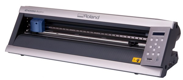 Roland CAMM 1 Servo
A Vinyl Cutter is a computer-controlled machine that allows us to make precise cuts on vinyl sheets. Vinyl cutters typically use a knife held by the cutting carriage to make these precise cuts
Vinyl cutters can be used for cutting stickers, designs, decals, shapes, icons, and even make masks for sandblasting, spray paint stencils etc,. and we could even cut out flexible circuits
Machine SetUp
We start of by loading the sticker roll or sheet by releasing the loading lever and aligning the paper
Once we have aligned the vinyl paper we align the pinch rollers to the white lines and push the loading lever, locking the sheet down to the cutter
White lines are marked right above the gripping points of the grit roller in order to hold the paper in place
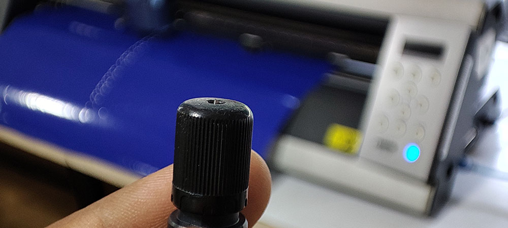
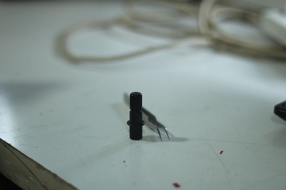
Then we can finally set up our vinyl cutter and set an origin and make a test cut using the test button. Test cuts are made to ensure whether the machine is functioning properly and making proper cuts. If not, then the we must adjust the force or set the blade height using the screw
We ensure the machine is functioning well by peeling out the outer circle without square inside doesn’s peel out Once the Test Cuts are made we are ready to go…
Design Phase
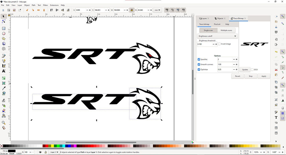
I used InkScape to create the vector for cutting the sticker. So I i first imported a low res .JPG of a logo and then using “Trace Bitmap” converted it into a vector
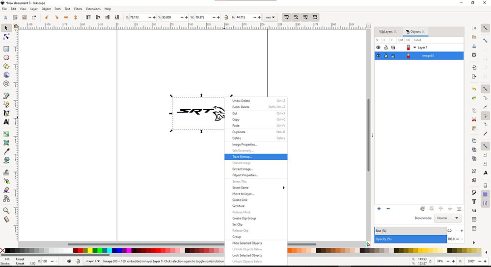
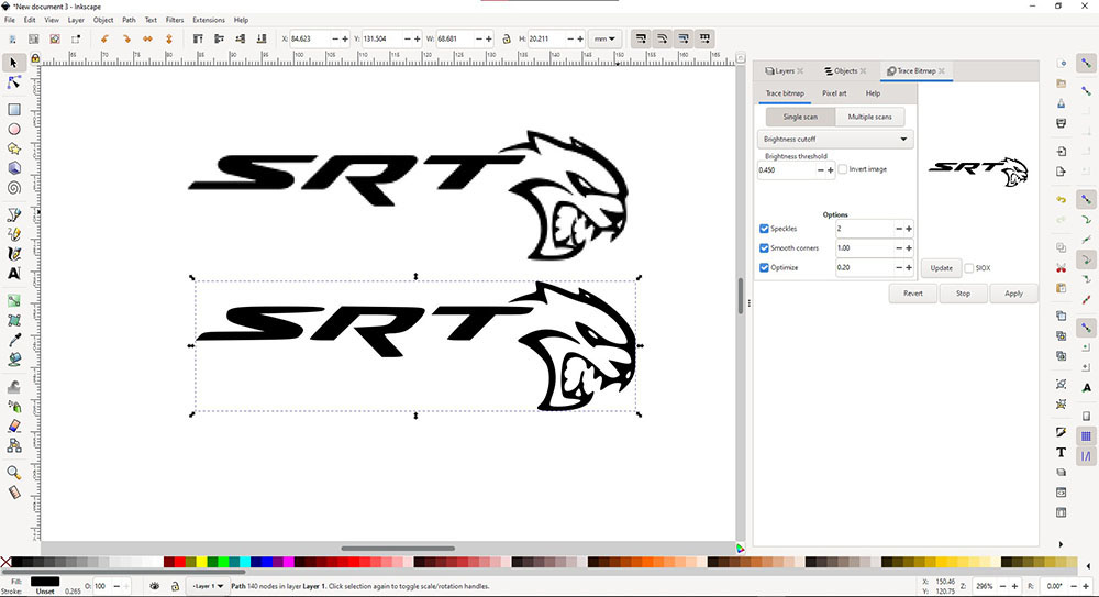
Since the .JPG was low res inkscape couldn’t define a perfect vector as you can see the letters look slightly bent and curved, and since I couldn’t get a medium res image of my desire I thought of importing them separately and then alinged them and goruped them and then converted it into a vector and the result was looking amazing and it was ready for cutting so I exported it as .PNG and we are almost there
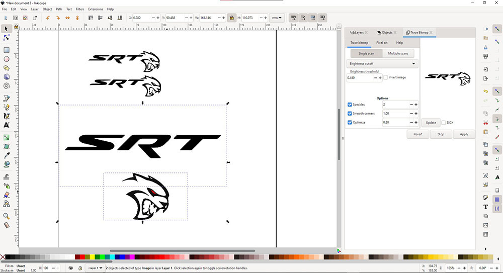
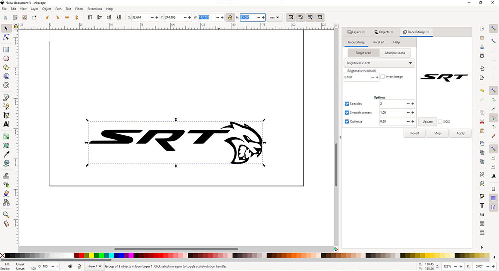 Final design in .PNG format…
How does the Machine communicate with the .PNG
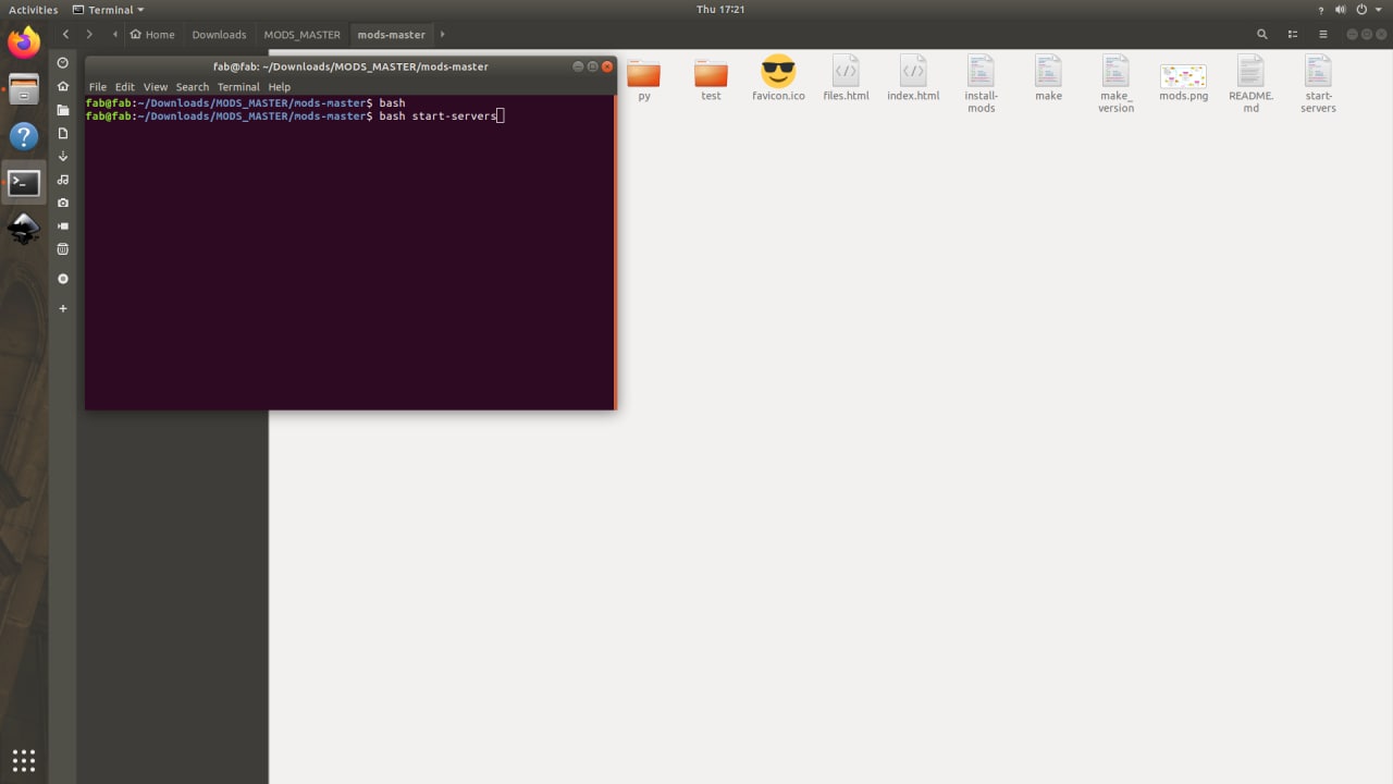
Since the design file is a .PNG file it doesn’t have enough infomation that directs the Vinyl Cutter nor gives it a path to follow so we use Mods
To start cutting we must first run Mods by opening terminal and typing in “bash start-servers”…
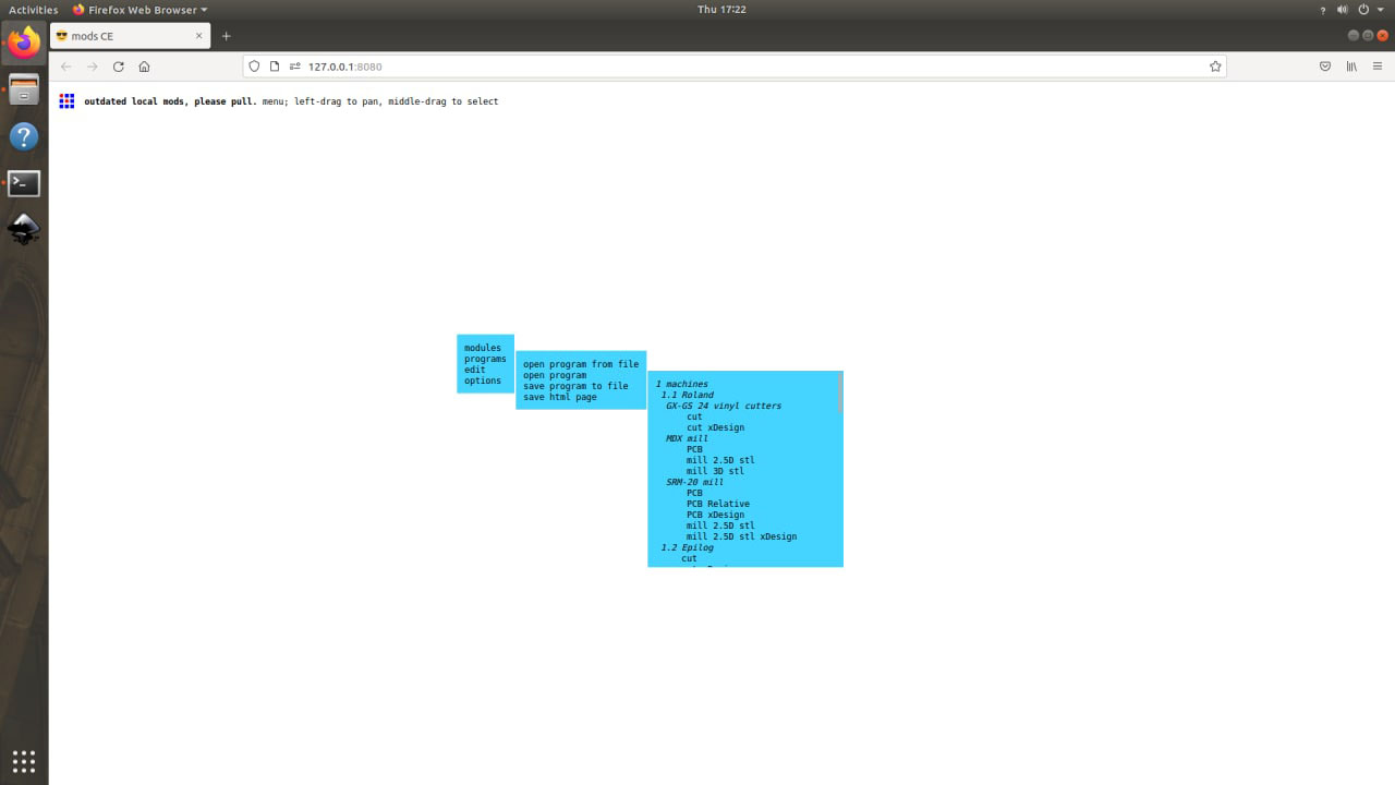
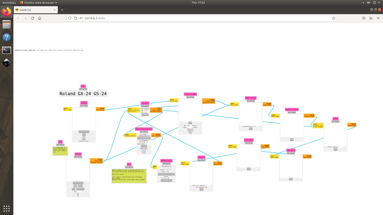
 Then Right-Click on the page and navigate to “programs>>open program>>GX-GS 24 vinyl cutters…
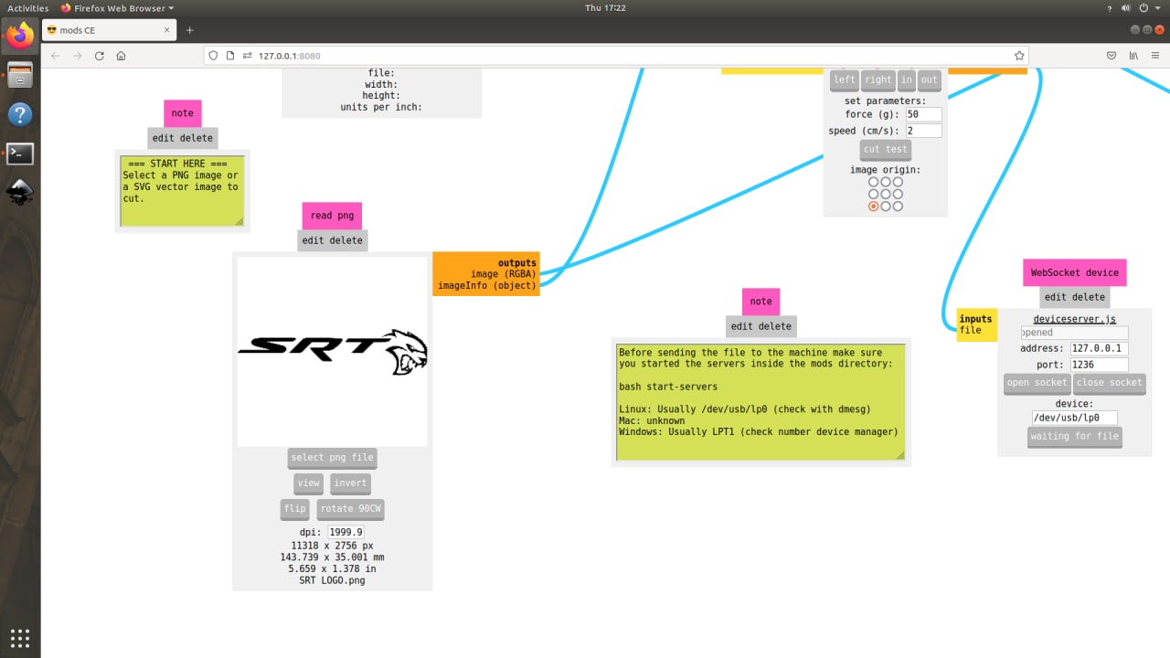
 Then we import our .PNG into mods by clicking “select png file” button..
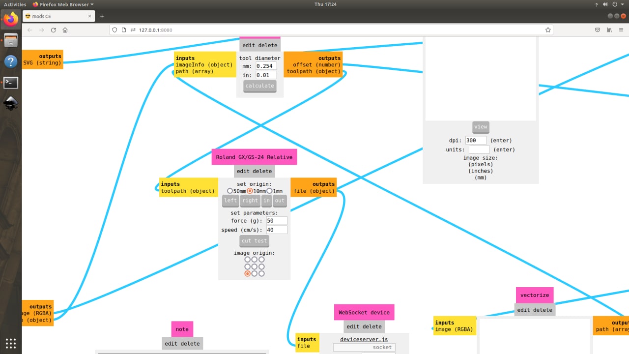
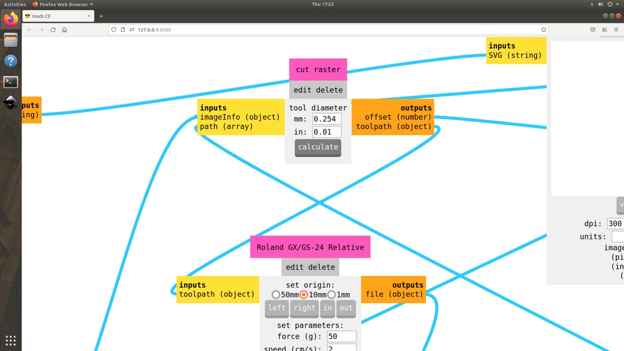
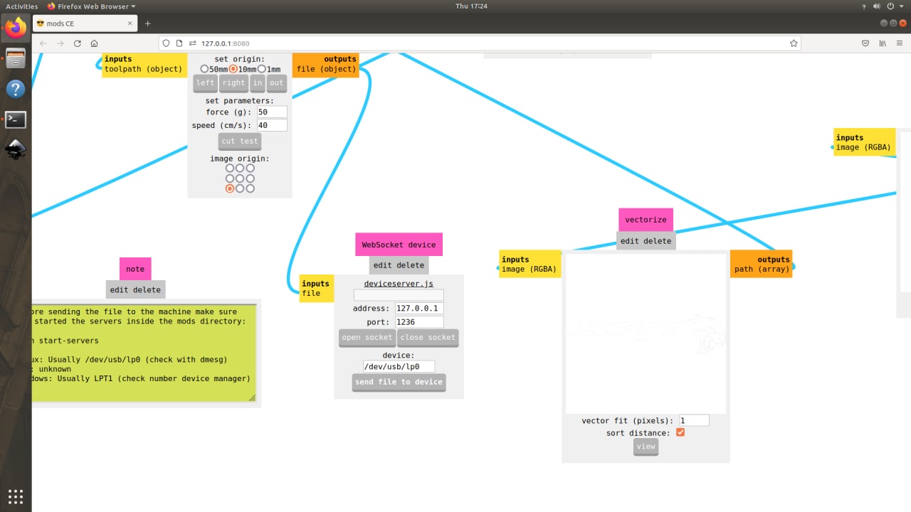
 …and set the force and speed under “Roland GX/GS-24 Relative” tab, and hit calculate under “cut raster” tab…
 …then we click “open socket” and finally click “send file to device” under “WebSocket device” tab to start cutting
Once we are done with the cutting we can then remove the remaining sticker out…
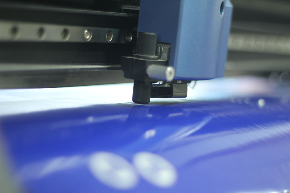
Cutting Phase
Like mentioned above the Vinyl Cutter uses a tiny knife that is allowed to rotate on a free axis using a ball bearing
Notice the knife spinning freely as it moves…
Application Phase
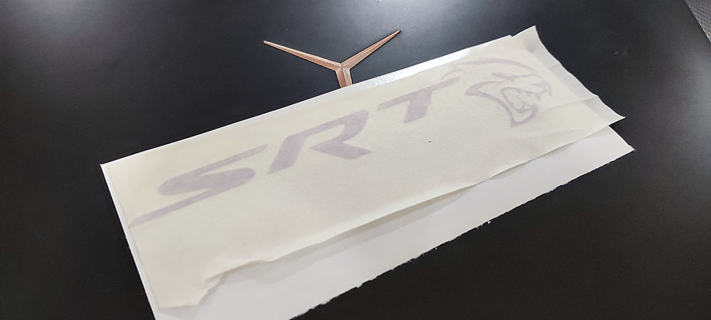
Now that the vinyl has been cut we have to peel out the remaining bits so we can use a transfer tape to transfer our sticker to the designated surface
This video was taken for documentation process…
p.s: No sticker comes off that easily
Now we apply a transfer Tape(we have used masking tape) and remove the backing paper so the adhesive side faces the surface we want to stick on and finally peel of the transfer tape
 p.s: again peeling sticker is the most time consuming process hence the .GIF…
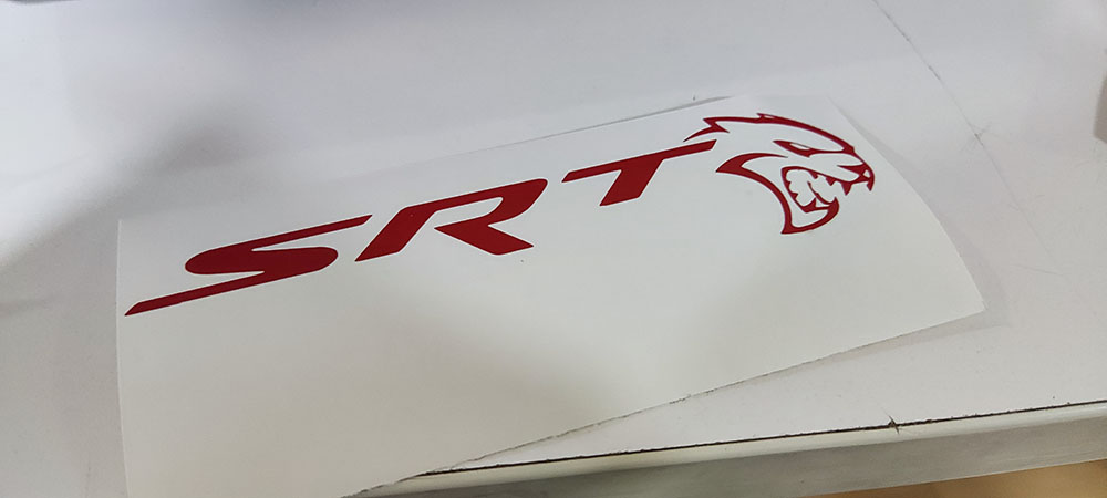
 And We’re Done!!!..
Laser Engraver
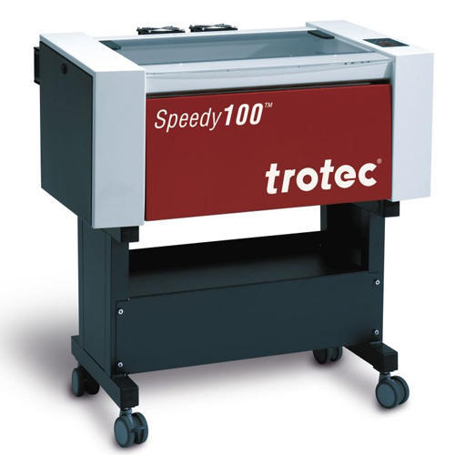 trotec Speedy100
A Laser Engraving machine is also a computer-controlled machine that is typically used for engraving and cutting differnt types of media like acryilics, wood, cardboard, metals, etc.. The Laser emmits a beam that is reflected using mirrors and focussed onto our medium and burns into the material making precise cuts and engraving
Machine SetUp
There are many aspects we need to rectify while setting up the machine as each material will require different properties such as power, speed, and kerf, and so we decided to do this as a group
KERF - While doing any cutting process there is a width of material that is removed by the cutting medium which is called kerf
We have done these tests in the Group Assignment Page
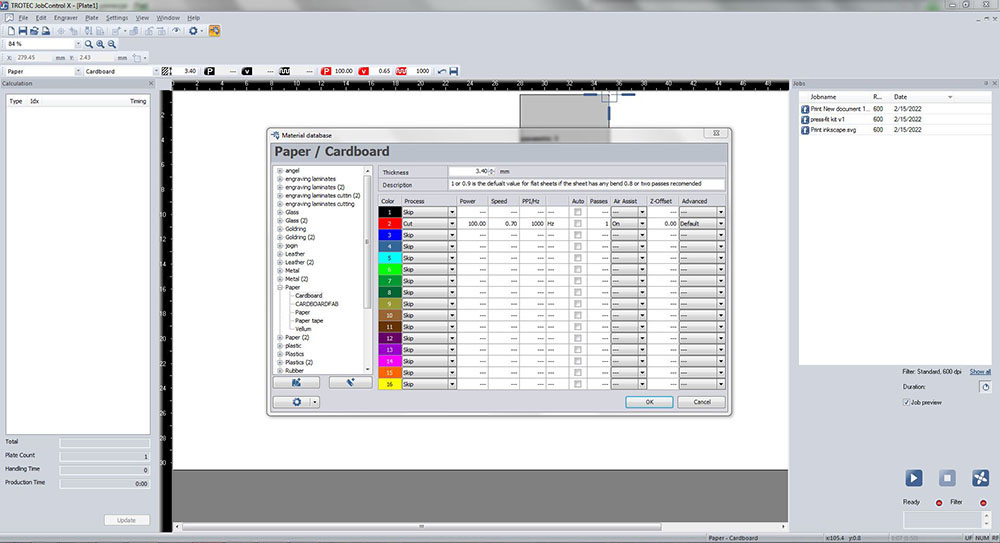
Here are a few of our group tests results Acrylic Cutting Power=100 Engraving Power=70 Cutting Speed=0.4cm/sec Engraving Speed=60cm/sec Number of passes=1 Frequency=1000
Wood Cutting Power=100 Engraving Power=70 Cutting Speed=0.2cm/sec Engraving Speed=60cm/sec Number of passes=1 Frequency=1000
Cardbord Cutting Power=100 Engraving Power=70 Cutting Speed=1cm/sec Engraving Speed=60cm/sec Number of passes=1 Frequency=1000
Following are the kerf of materials we found out Acrylic 20.20-19.87= 0.33 kerf=0.33/2 kerf=0.165
Wood 20.41-19.8= 0.61 kerf=0.61/2 kerf=0.305
Cardbord 20.35-19.84= 0.51 kerf=0.51/2 kerf=0.255
Now that we know how to find the kerf and found the best settings for each media lets focus the laser by first placing our material on the work bed, and hanging the focusing tool on the laser head. Now using the navigation keys on the contol panel we raise the work bed until the top of the material gently touchs the focusing tool which falls on touch
Design Phase
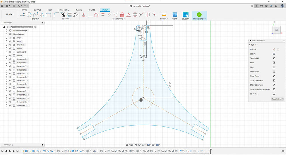
Me being new to Fusion360 this took me the longest time to make a parametric pressfit construction peice design and me being a perfectionist I wanted to make something not just unique but something that is small and universal, like a single or two peice construction kit with different possibilities and so I started designing in fusion by adding in the parameters
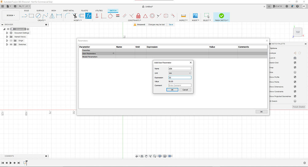
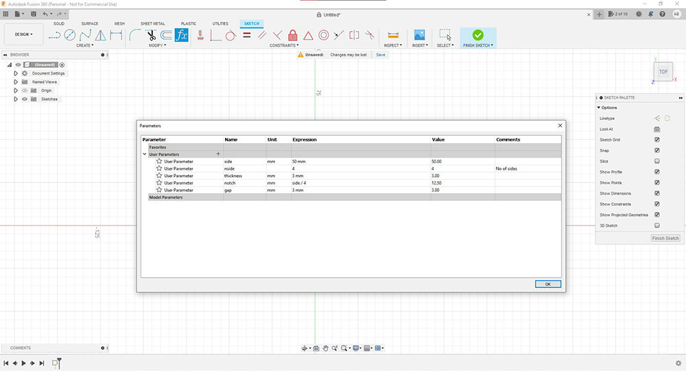 Adding Parameters to the Parameters table…
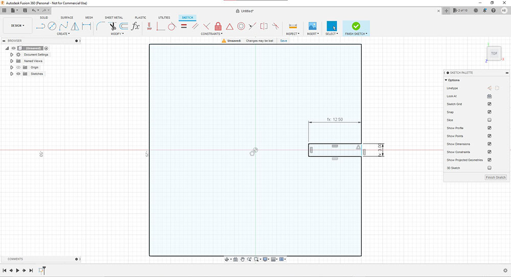
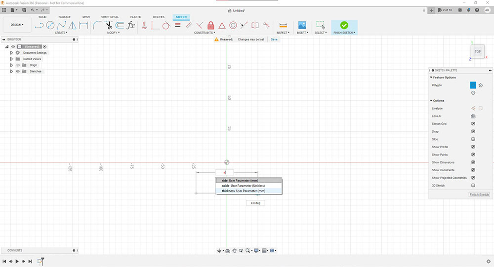
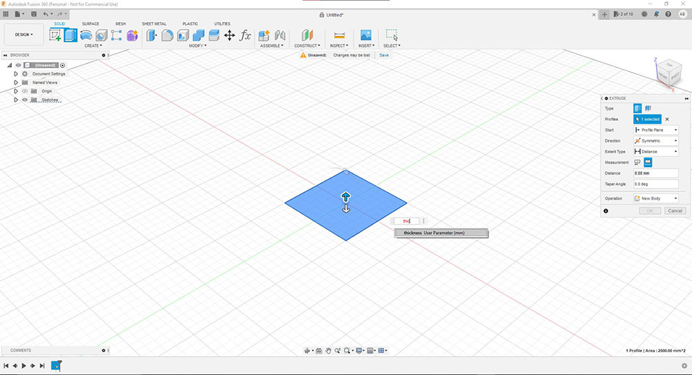
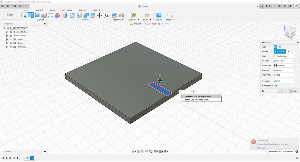
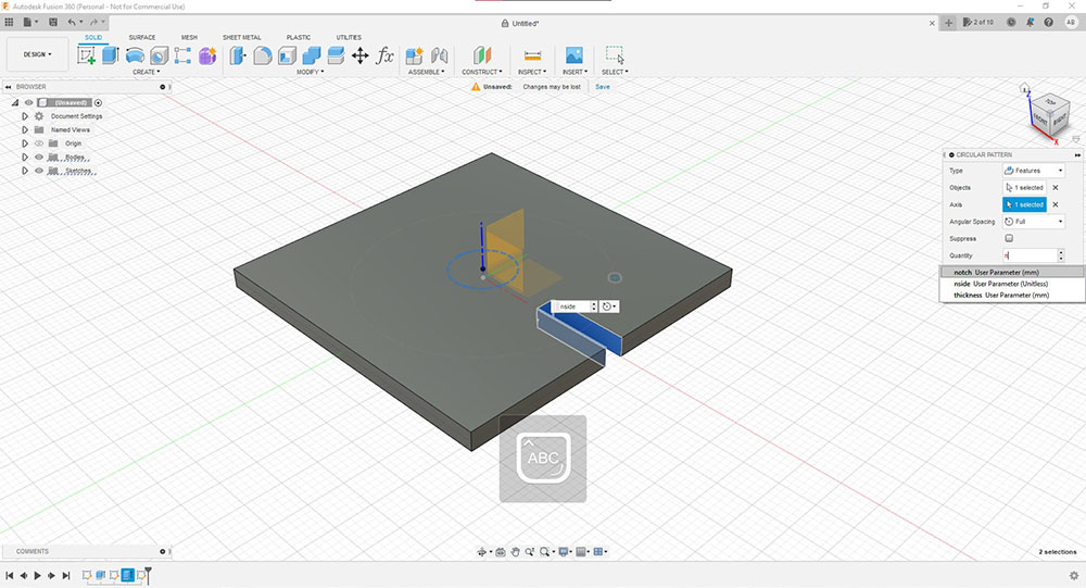
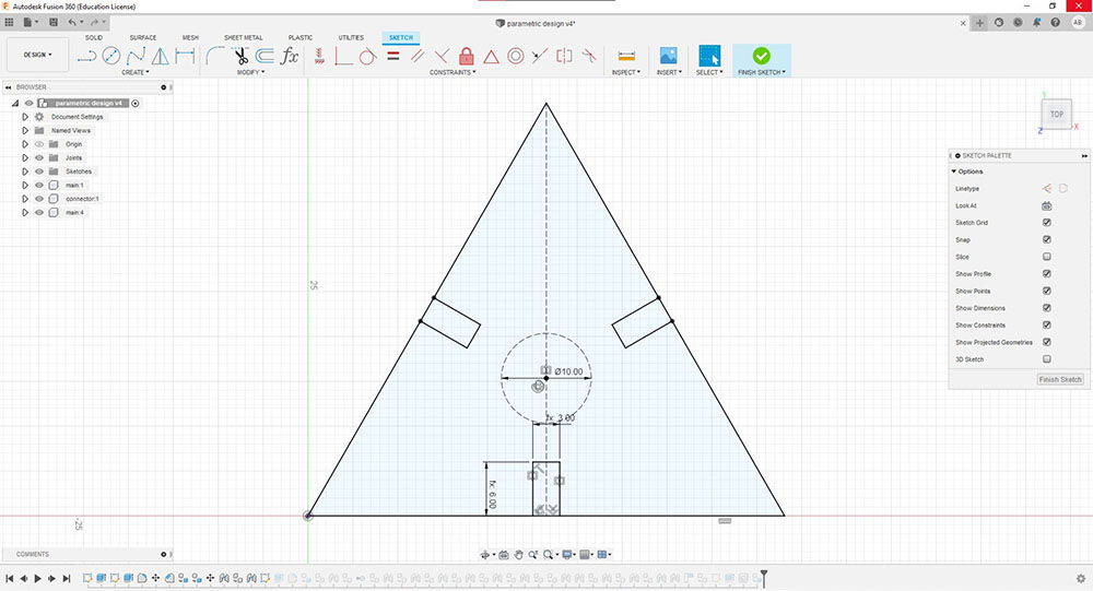
Adding parameters to the design…
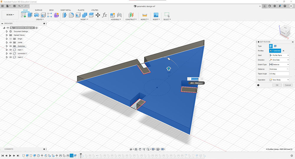
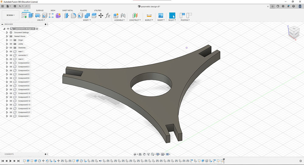
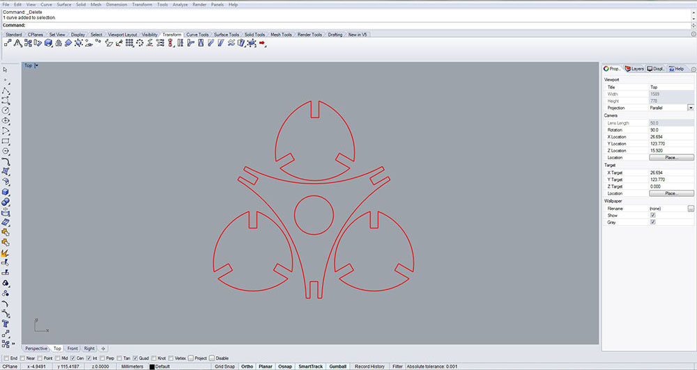
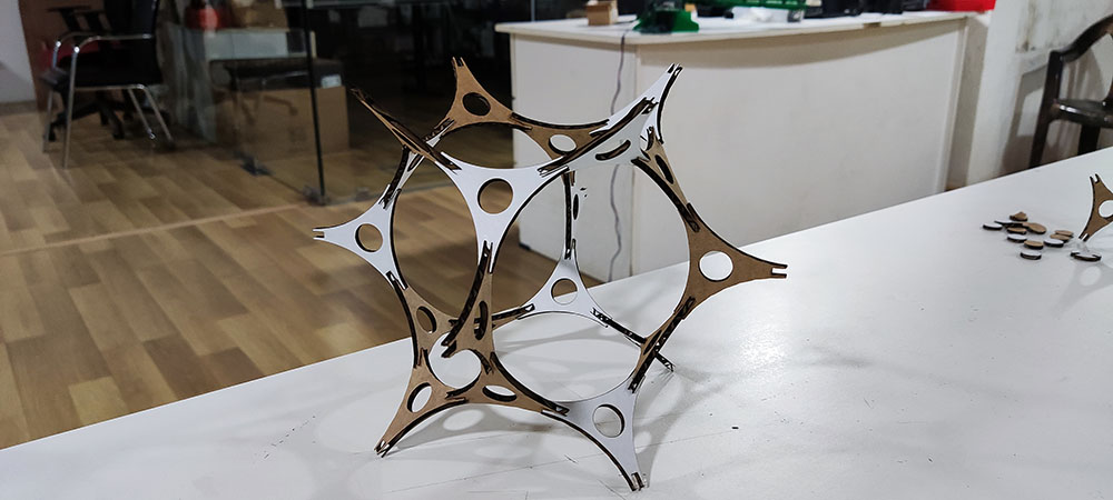
After many drafts I finally came to final design of my construction peice
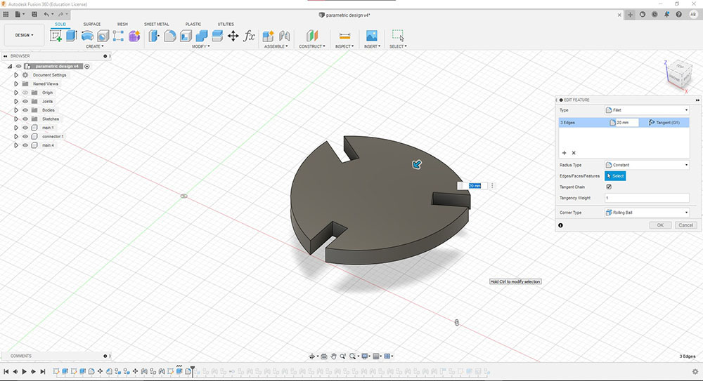
Since I was new to fusion and curious to try the assembly tool in fusion I tried something different
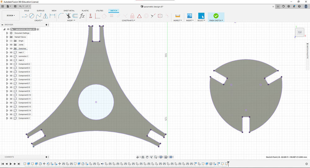
Seeing all the endless assembly possibilities I made a second construction peice in addition
And finally we export the sketch file as .DXF to run it on our machine
How does the Machine communicate with the .DXF
Being a .DXF file and being a vector we still need more information to direct the machine including and to do so we first import it into Rhino and give our .dxf vector design a few attridbutes like changing the line-color to Red, Linetype to continueous and print width to hairline
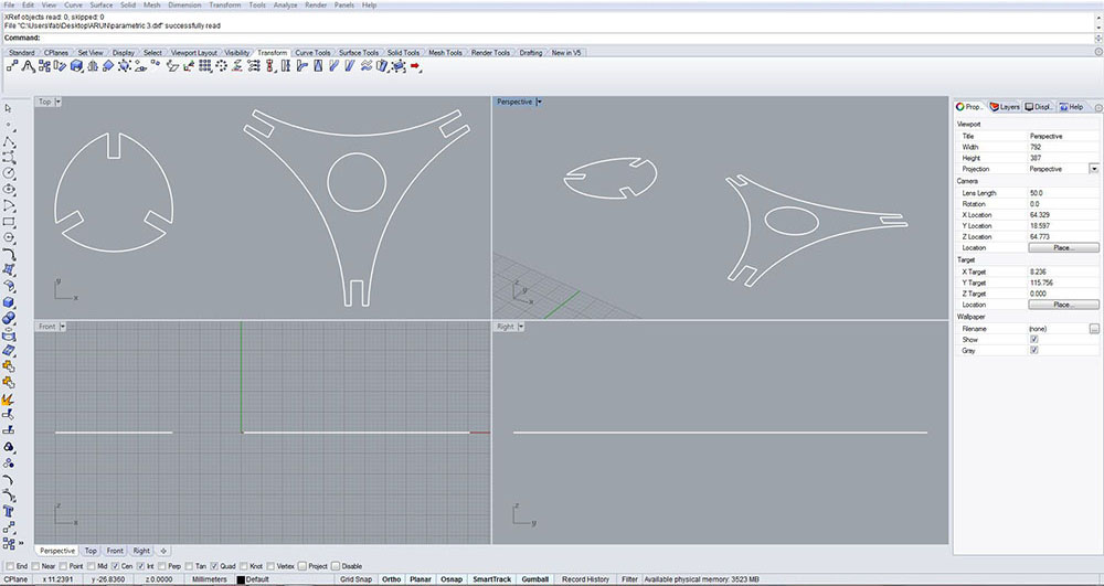
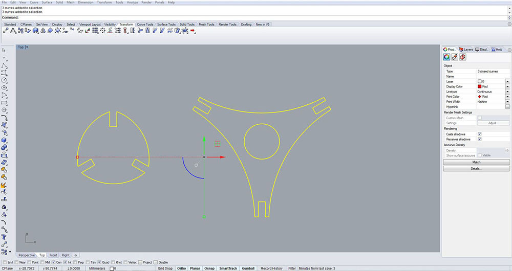
As we see above red denotes to cut through
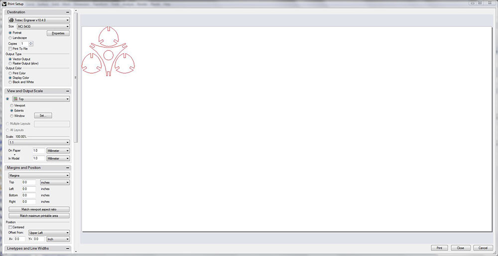
Now that we have given it enough attributes we can directly give the “Print” command from Rhino and select “Trotec” as the printer under the print properties which directly opens up (the dedicated prgram for the machine) “TROTEC Job Control” window.
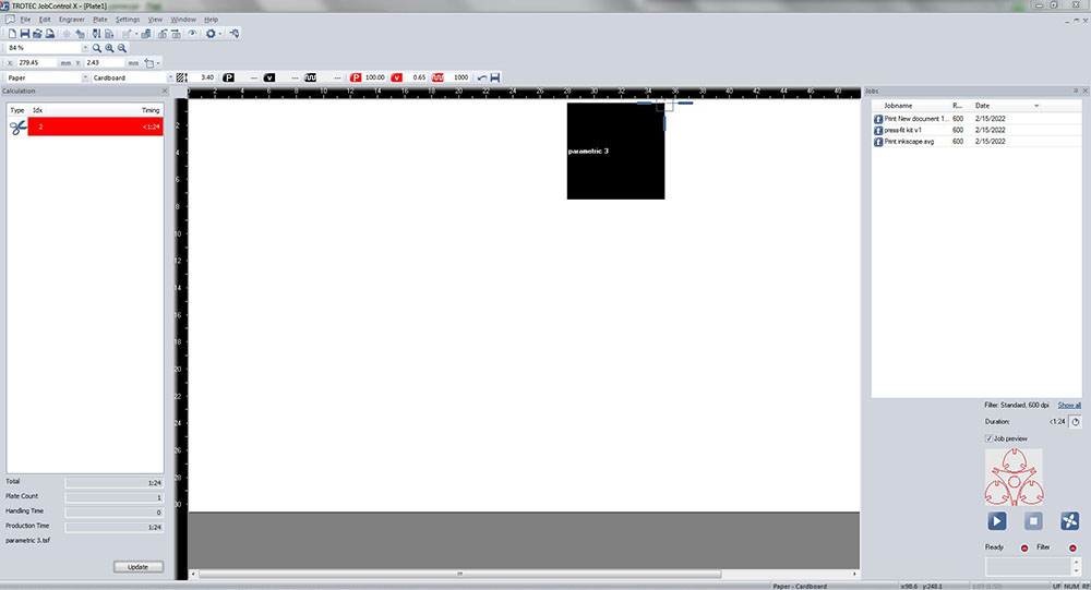
We can then change the properties such as power and speed of the laser machine and finally just drag and drop it from the Job list to the Job area where you can see a crosshair which defines the position of the laser head wit hrespect to the machine itself. We can position it where ever you want with respect to the work bed or just move the laser head to a specific point on the bed using the navigation keys on the control panel on the machine and just drag the file and snap it near the crosshair in the program and hit “Ready”
Cutting Phase
Once we hit ready the laser starts cutting or engraving
Always ensure that the air filtre is turned ON and always keep an eye on the laser as it has the tendancy to catch fire
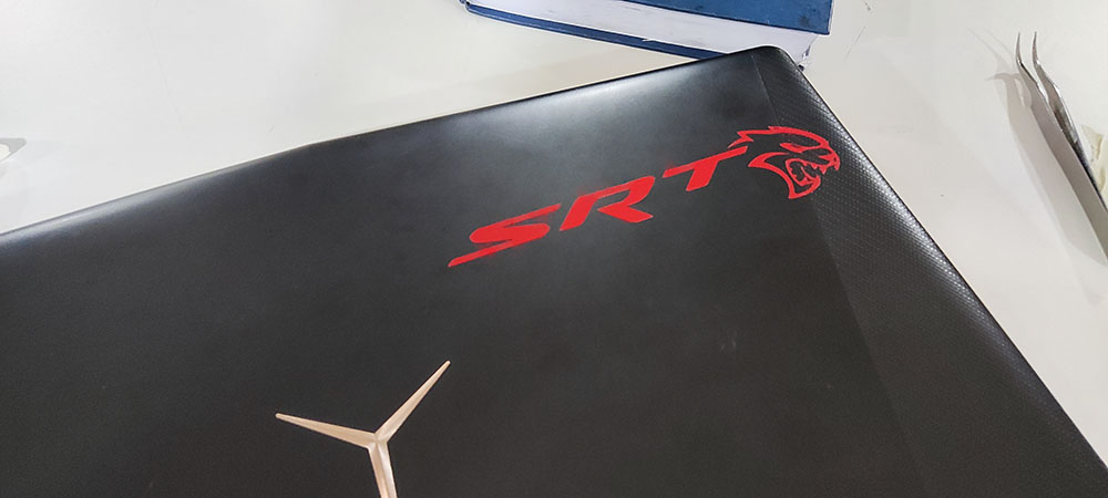
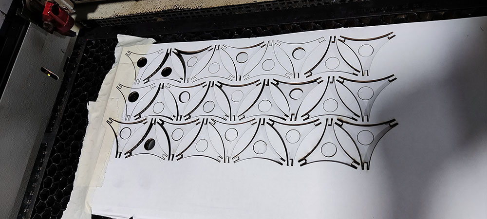 This is how it looks after a cutting session…
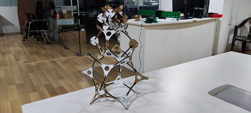
Assembly
And finally we assemble them
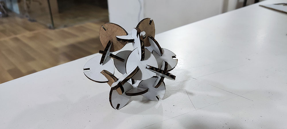
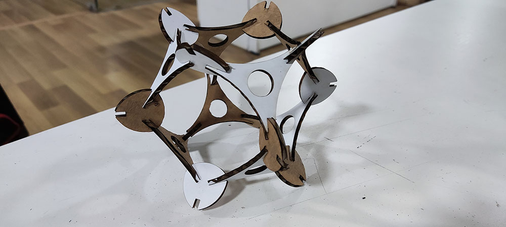
Can also be used like a fidget spinner
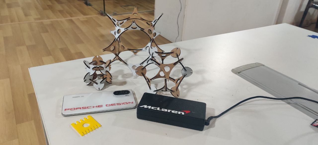 This is everything I did this week