4. Electronics production
WEEK 4
This week’s assignments are:
- To learn to characterize the design rules for your in-house PCB production process(Group Assignment added HERE)
- To make an in-circuit programmer that includes a microcontroller
- To customize the design, mill and stuff the PCB and test it to verify that it works
PCB Milling
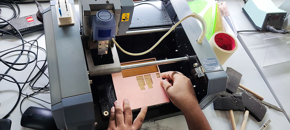
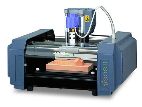 Roland MODELA MDX-20
We used this 3D Milling Machine to engrave and cut the PCB boards. This is another computer controlled machine that uses a toolbit to machine the given design of a PCB
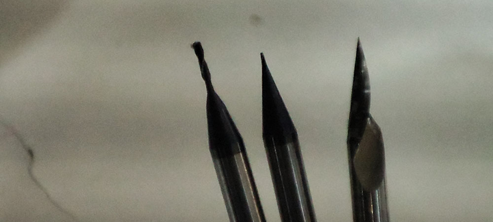 These are the toolbits we used..
3D Milling machines are also used for milling wax molds for jewellery, casting(Machine parts, Jigs, etc., ), etc.,
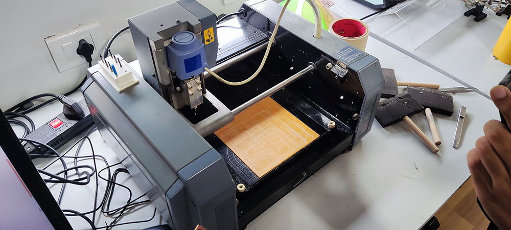
Machine SetUp
The machine setup is pretty basic for this machine and the two main components that need to be set up are the machine bed and the toolbit
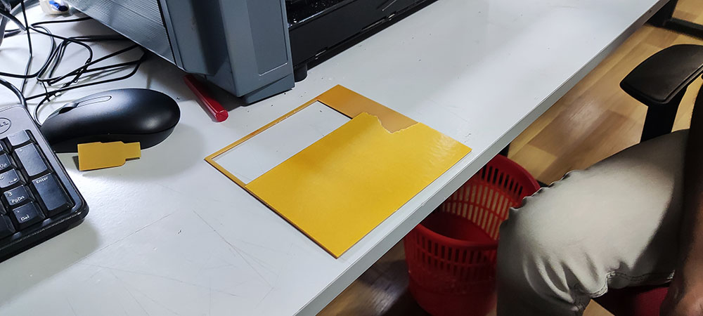
Setting up the Machine Bed
Since the sacrificial layer was already installed I started by apllying double sided tape to the back of our board
 The Sacrificial Layer…
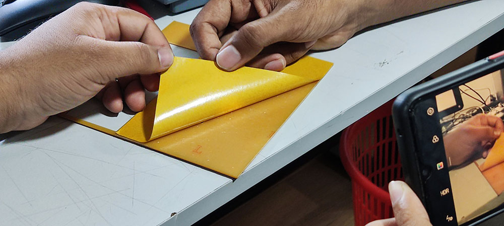 Applying double sided tape to the back of the board
After peeling off the tape backing we aligned and fixed it onto the sacrficial layer
Then I fixed the toolbit onto the spindle, then zeroed down the toolbit to just touch the material and the tightened the bolt to hold it in place
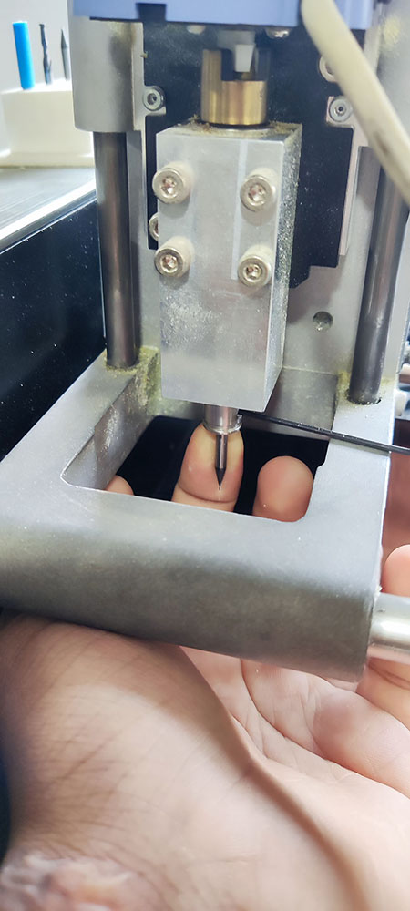
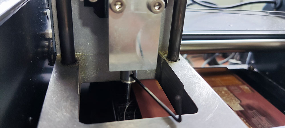 And just like that the setup is complete
Milling Phase
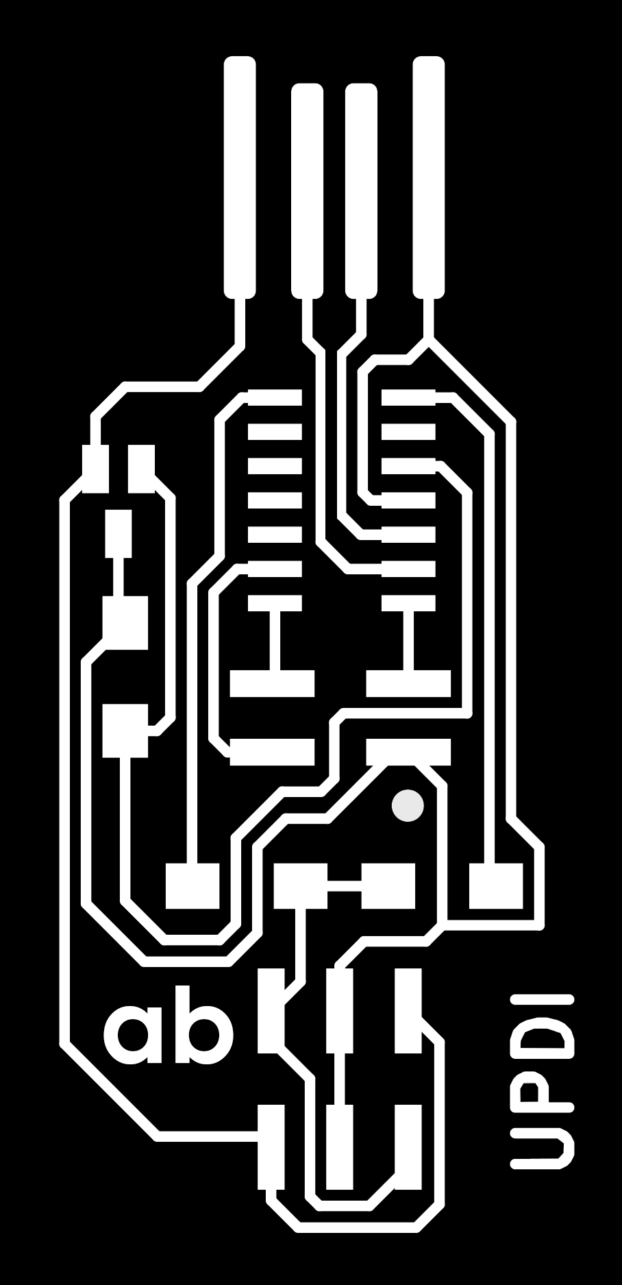
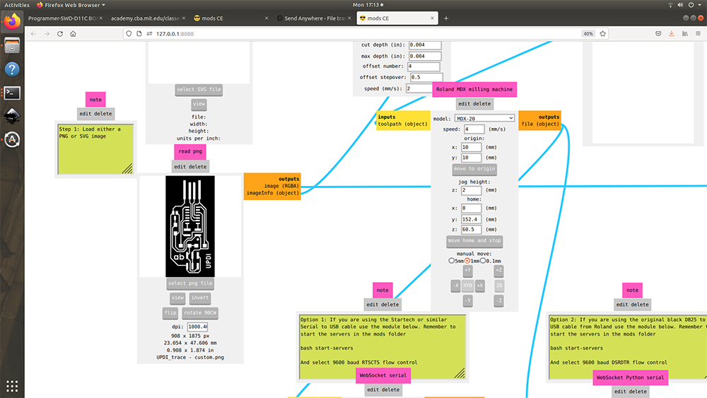
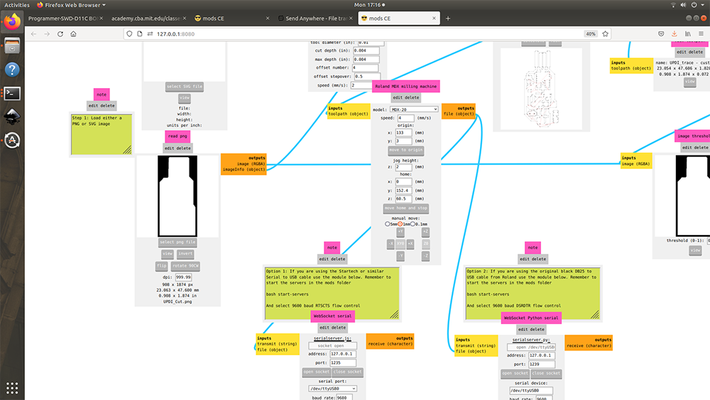
To mill it with the PCB miller I first downloaded the UPDI D11C .SVG file from the Fabcloud “programmers” repository (click here to download) and for some personalisation I added my initials “ab” for engraving and then exported it to .PNG and then traced the outline to get the border vector for cuttting and exported it to .PNG.

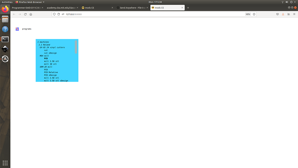
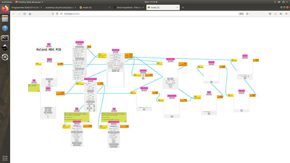
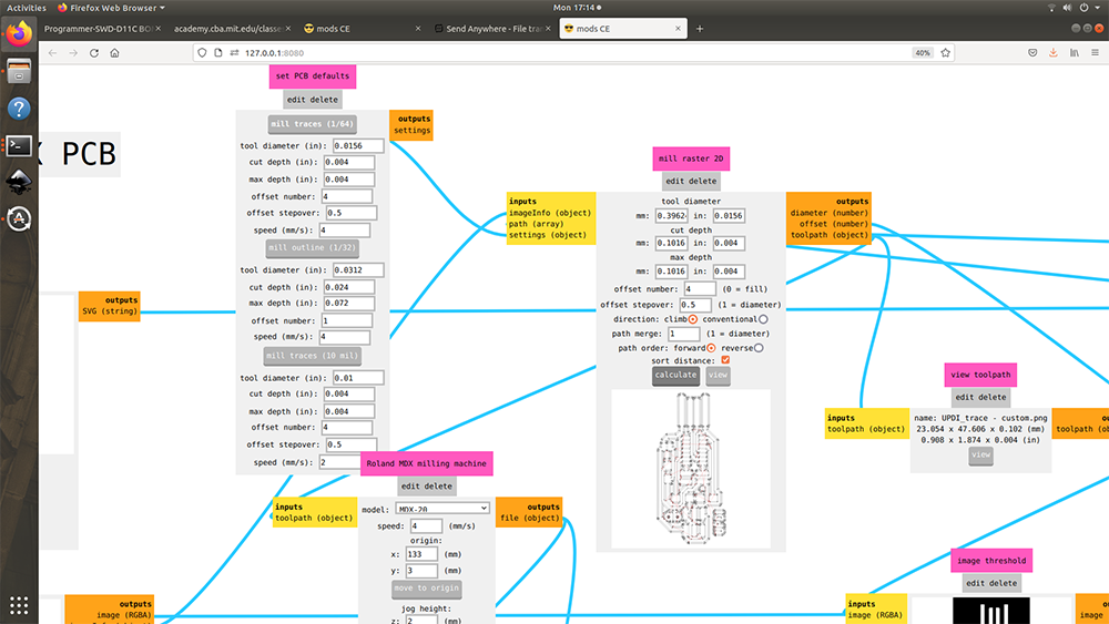
Then using mods we imported the .PNG and milled the PCB board using the 1/64” toolbit for engraving and a 1/32” toolbit for cutting
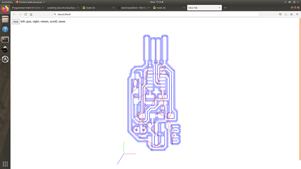 This is the engraving toolpath
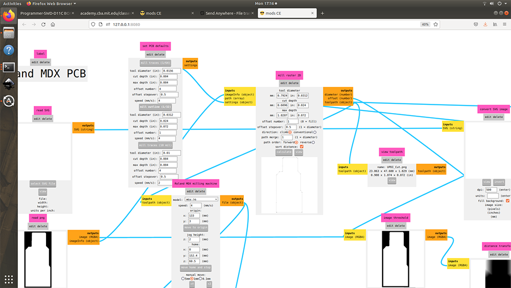 This is the cutting toolpath
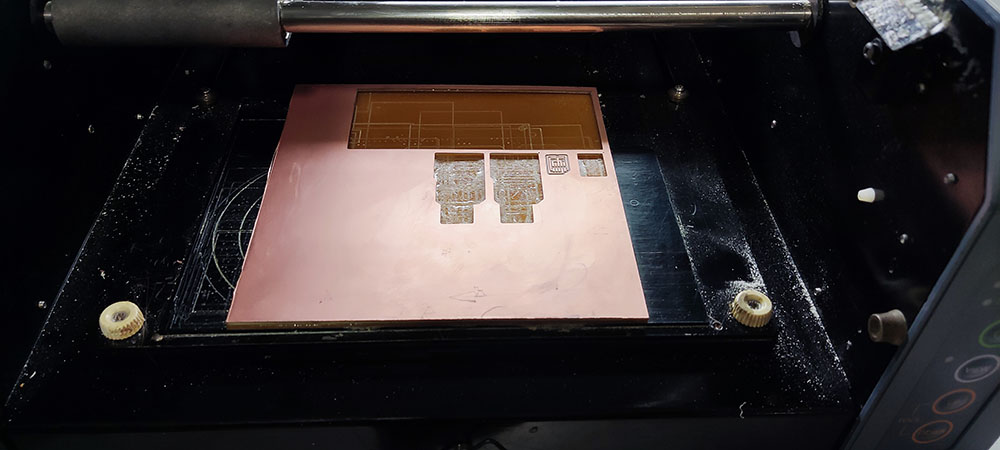
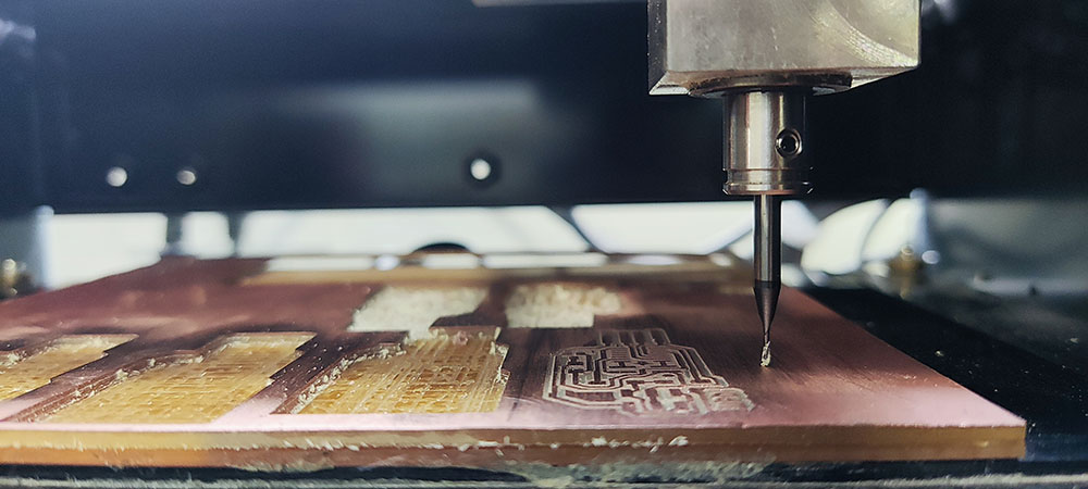
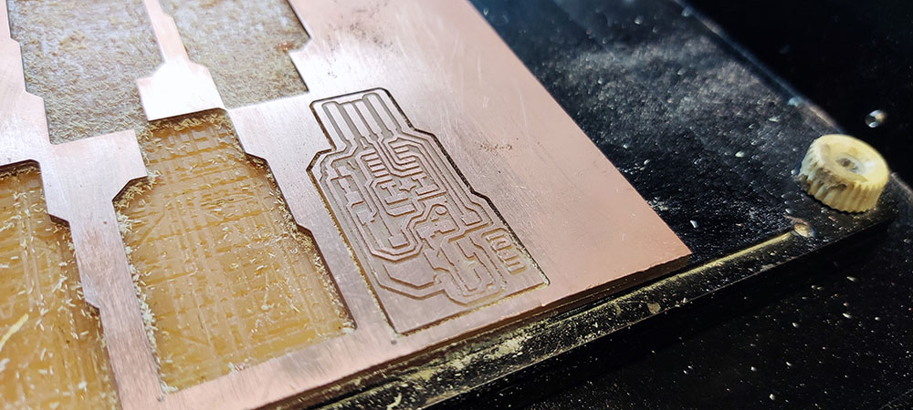
This is how the machine engraves into the material
Once the engraving was done I then vacuumed the little debri and then sanded it down to get neat creases
Vacuuming and cleaning the rough creases
Cutting the outline trace
 Post Mill
Removing the PCB
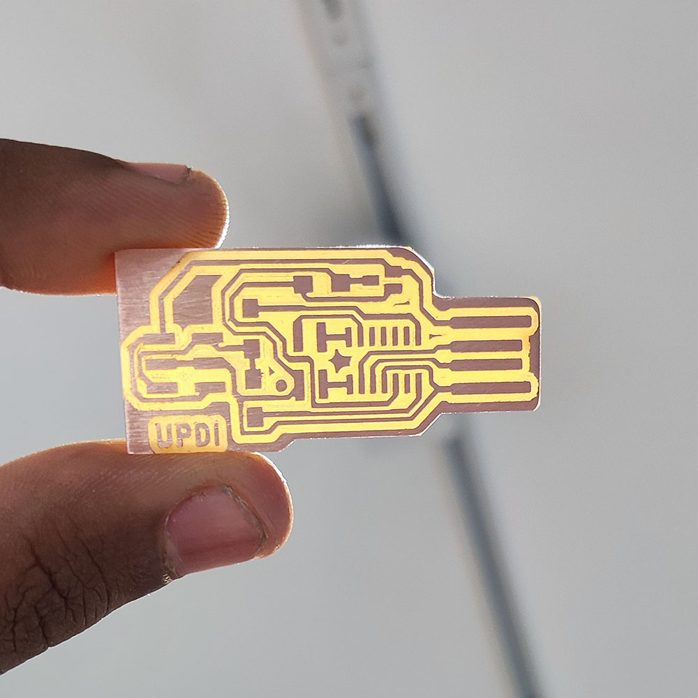 The End Product…
PCB Components
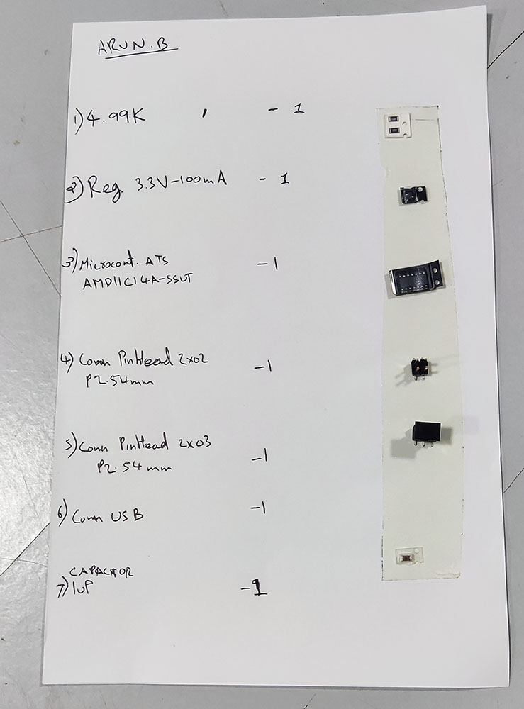
Now that the PCB is ready we need to add the components and turn this into working Programmer which we can use for our final Project
So in order to idenify the components I made a chart and stuck double sided tape and placed each component adjacent to the part name like so…
Soldering the PCB
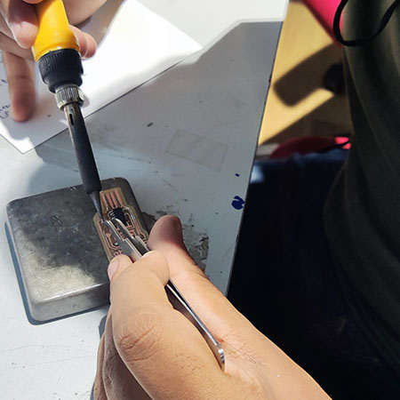
Even though I knew a little bit of soldering and desoldering from highschool science projects and client projects with LED light panels, I was still new to such smaller scale soldering especially something like the microcontroller which had 14 pins millimeters apart or smaller, but still took up the challenge to solder them as precisely as I can and set the soldering iron to a 355 and soldered away…
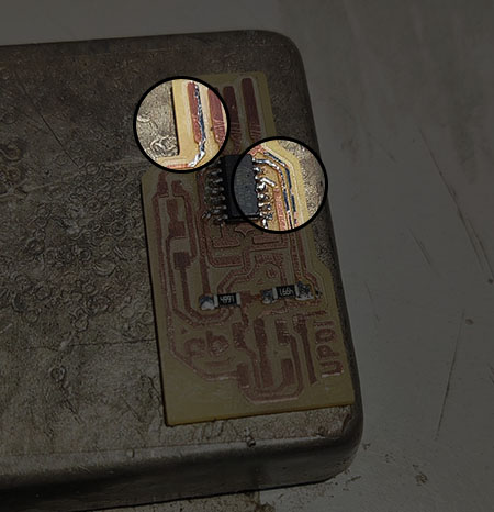 Notice how I messed up the very first solder and using the tip pulled the solder back and corrected it
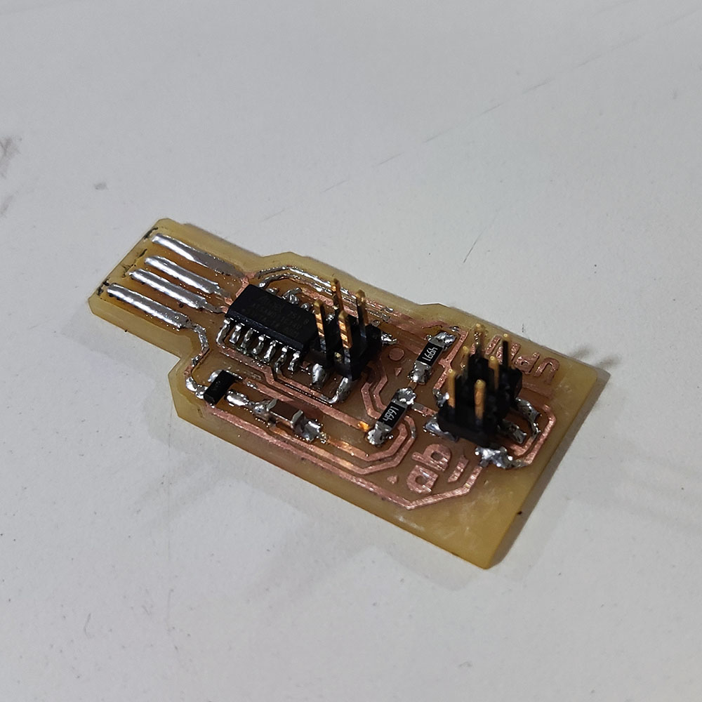 Post Solder
And Our UPDI Programmer is Readyy!!…
Programming My UPDI Programmer
A programmer is basically used for communicating with the IC(Integrated Circuit) so that we can teach it to do specific tasks by uploading information from a PC that way we can communicate with the assembly language with a high level language which is more understandable to us
But since I haven’t programmed my UPDI Programmer, I have to first teach it to be read by a USB port and for this I used an SWD programmer which was created for the lab for this same purpose
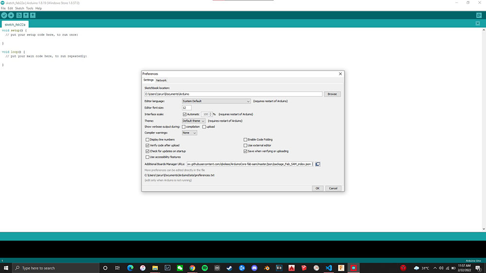
So first I connected my programmer to the SWD Programmer using the 2x2 connector and then opened Arduino IDE and installed SAMD Arduino Core by using this URL in the boards manager:
“https://raw.githubusercontent.com/qbolsee/ArduinoCore-fab-sam/master/json/package_Fab_SAM_index.json”
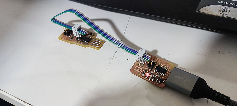 Programming the programmer with a programmer…
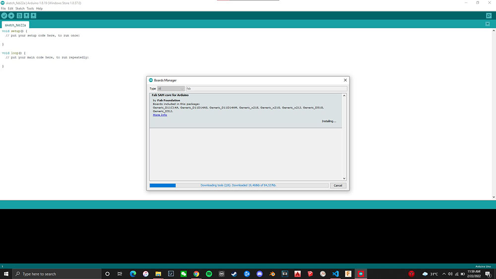
Now that I have the SAMD Arduino Core installed I can use it to teach our USB port to interact with my computer
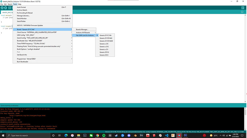
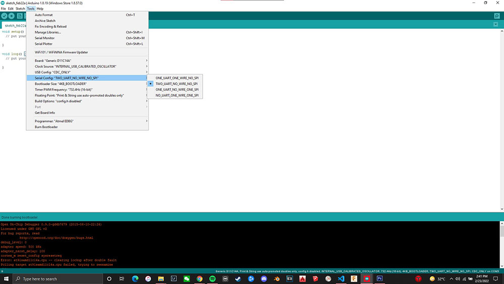
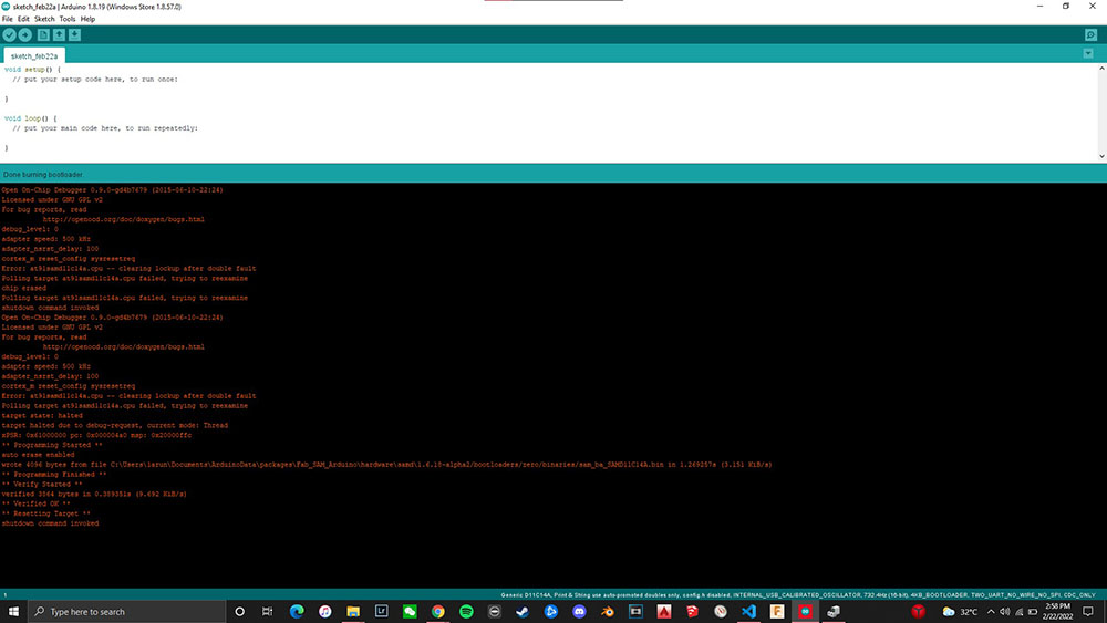
So first we select the SAM core and check the “Generic D11C14A” then under “Serial Config” we check “TWO_UART_NO_WIRE_NO_SPI” and then hit “Burn Bootloader”
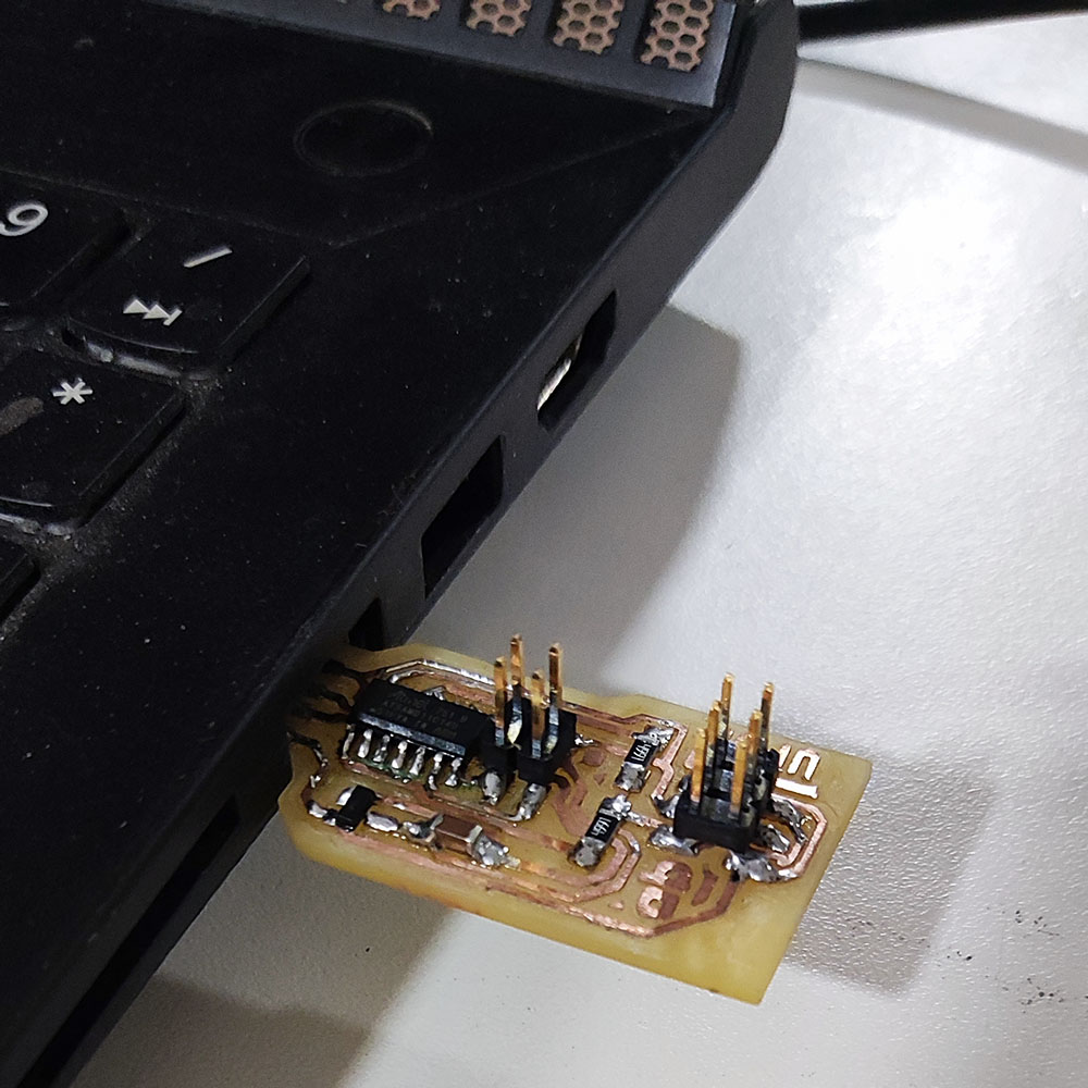
Now that my programmer can be read by the USB port of my computer I can now plug my UPDI programmer right into my computer’s USB port
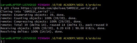
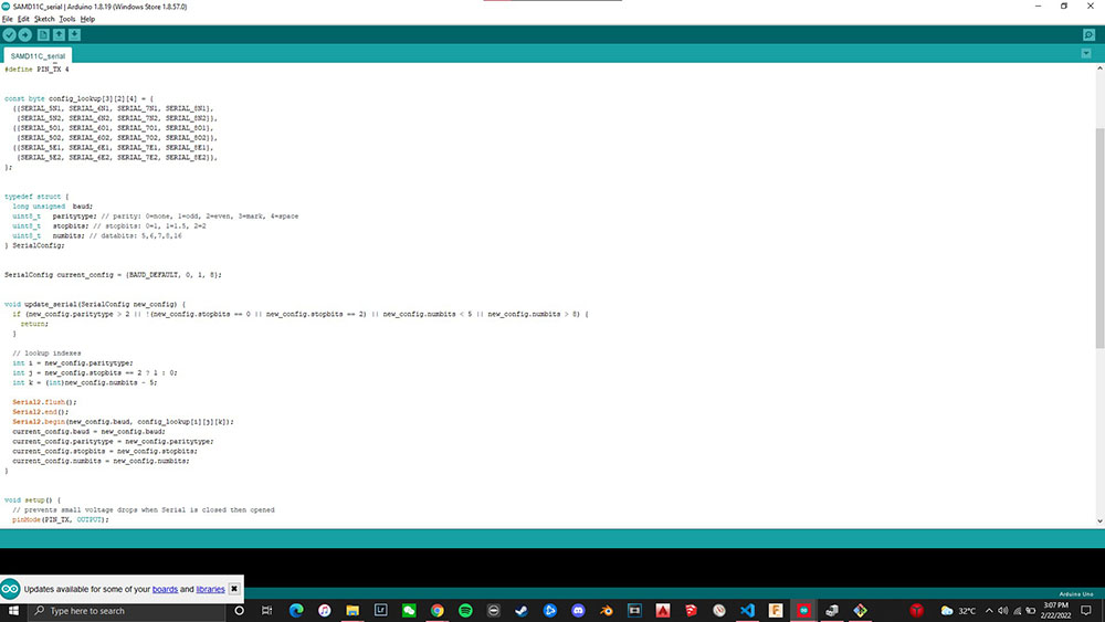
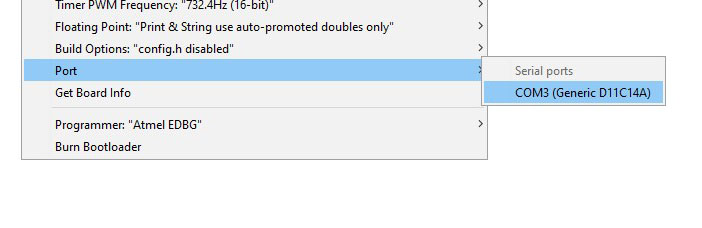
Once the USB recognises my Programmer we can use Git Bash to clone the SAMD11C serial repository from here and then open “SAMD11C_serial.ino” select the “Port” option in the “Tools” drop down menu and select “COM3 (Generic D11C14A)” and then we are ready to upload it into our Programmer
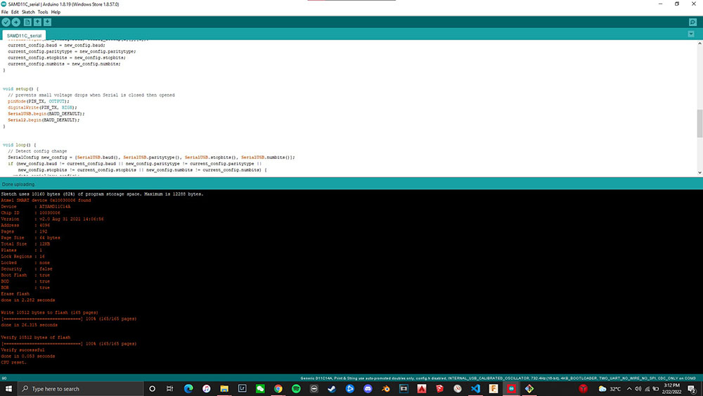
And now our programmer is hence a Programmer!!!.. ;)
Resolution Test
So one of the most crucial things to know while milling PCB’s is how close or far our circuit traces can be and to test that we are using this file…
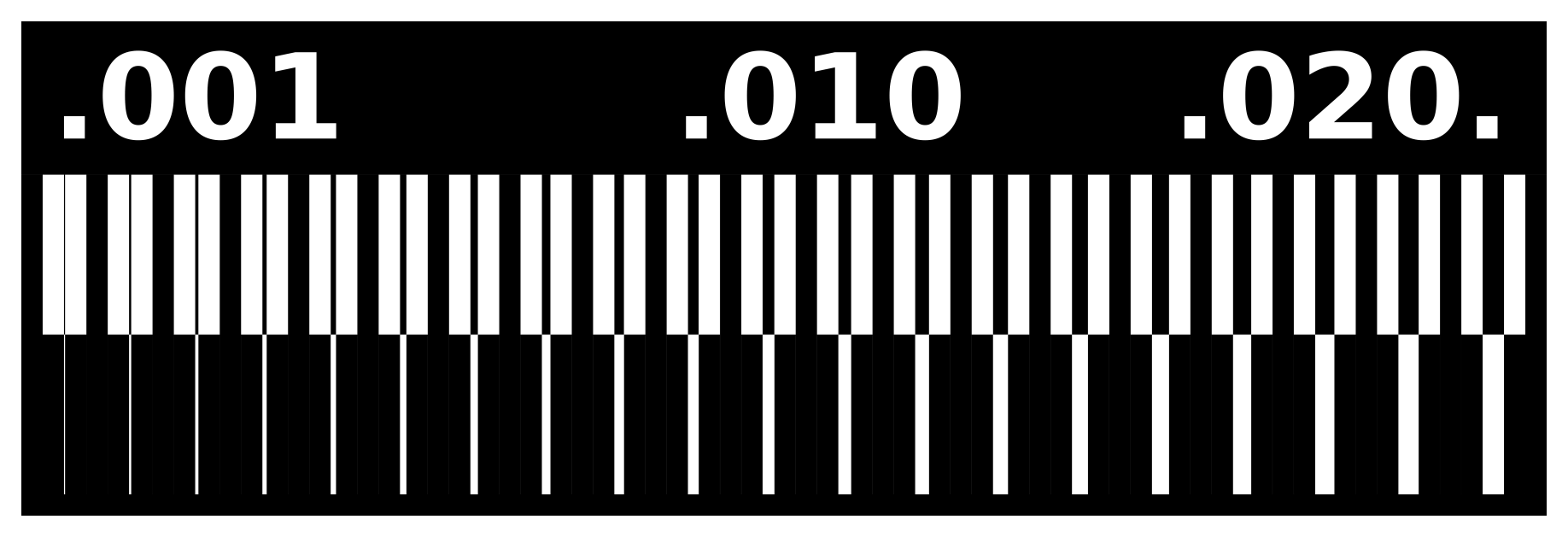 This will allow us to find how many mils our toolbits can engrave upto
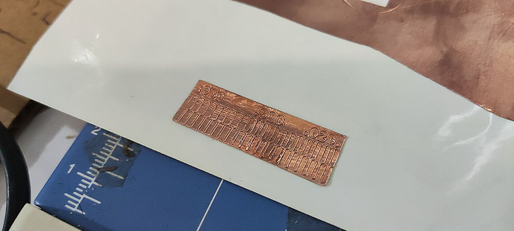
3D Milling Machine Test
For this we used the 3D Milling Machine with the 1/64”, 1/32” and the 1/100” toolbits and here are the results…
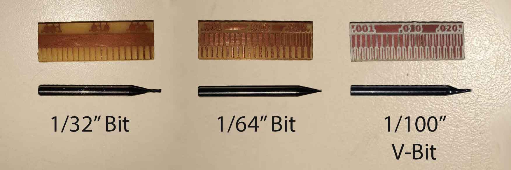
Conclusion:
We can conclude that
- 1/100” bit can trace upto 0.11mm
- 1/62” bit can trace upto 0.16mm
- 1/32” bit not suggested for engraving and better as cutting tool
Trying other ways to engrave
Vinyl Cutter Test
We also tried using the vinyl cutter to test how far we can cut and the results were amazing
 Before…
Weedingggg…
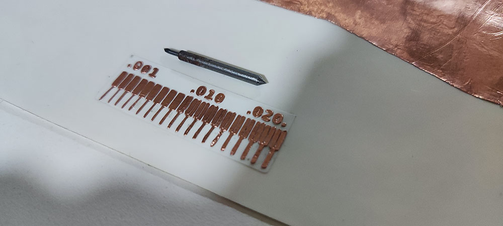 After…