6. Electronics design
WEEK 6
This week’s assignments are:
- To use the test equipment in our lab to observe the operation of a microcontroller circuit board(Group Assignment added HERE)
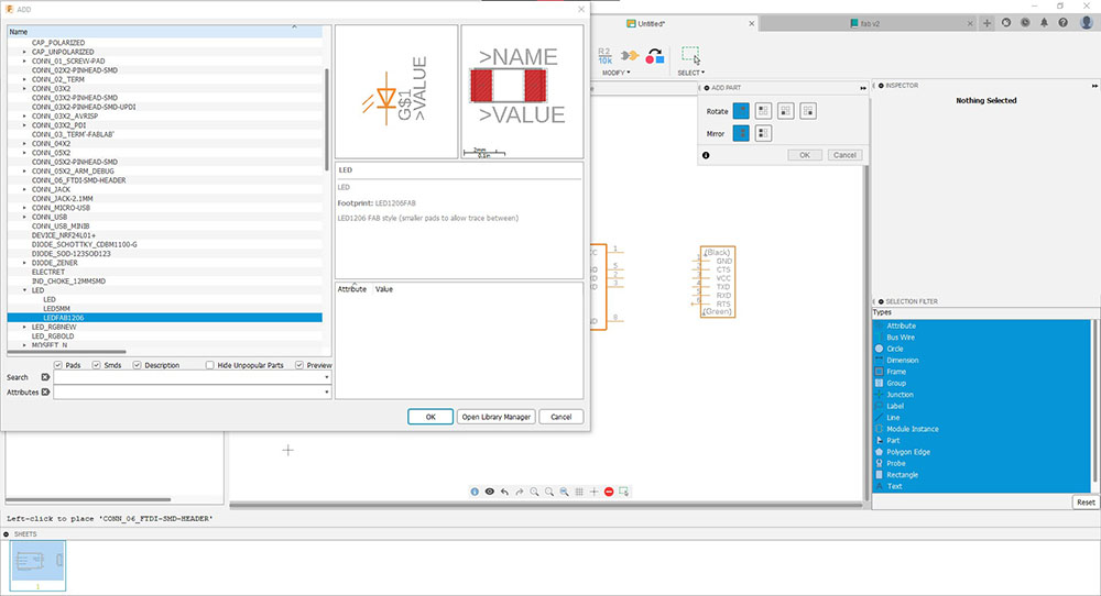
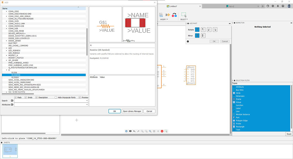
- To redraw an echo hello-world oard, add (at least) a button and an LED (with current-limiting resistor)
- To check the design rules, make it , and test that it can communicate and simulater ints operation
Design Phase
Though I had the thought designing a circuit was a very difficult process, I was happy that Fusion360 made it so much more simple for me.
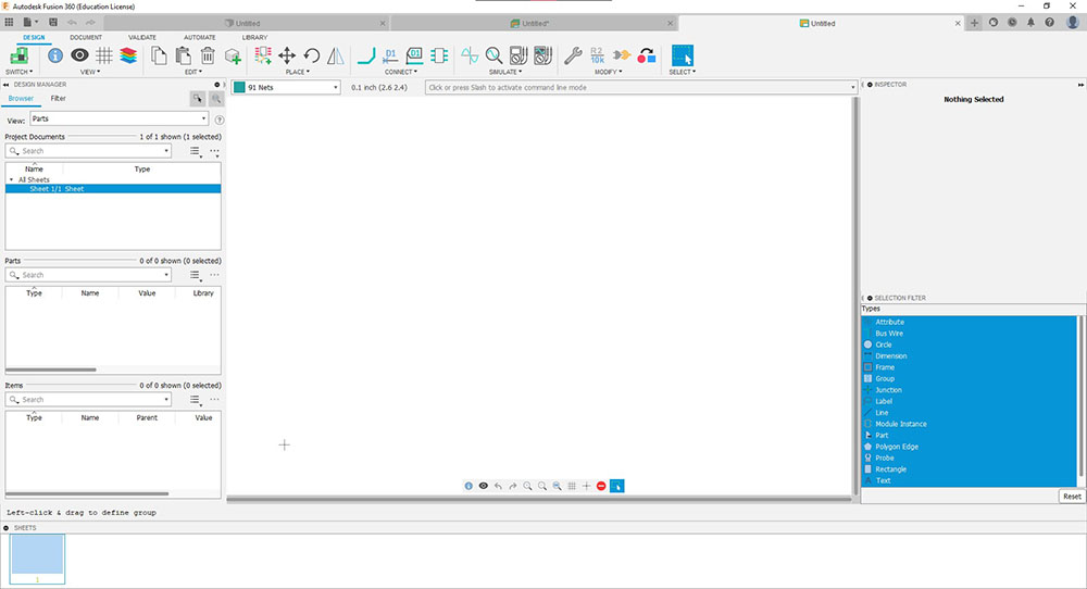
To start off I opened Fusion360 I started a “New Electronics Design” under “File” in the menu bar and opened a new schematic


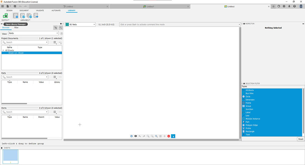
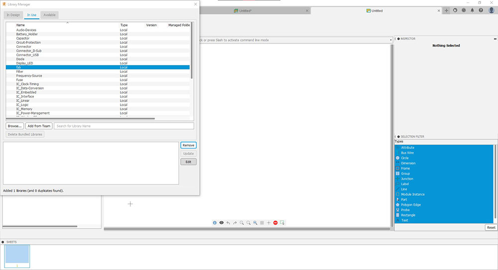
Then opened Library Manager under “LIBRARY” in the Tool Bar and under “In Use” tab I clicked browse and loaded the “fab” library(which I added by cloning from Eagle in the public repository in GitLab), I also loaded an ATtiny412 microcontroller which is the microcontroller that we are going to use

I am all set so I can start adding parts from “DESIGN tab in the tool bar…
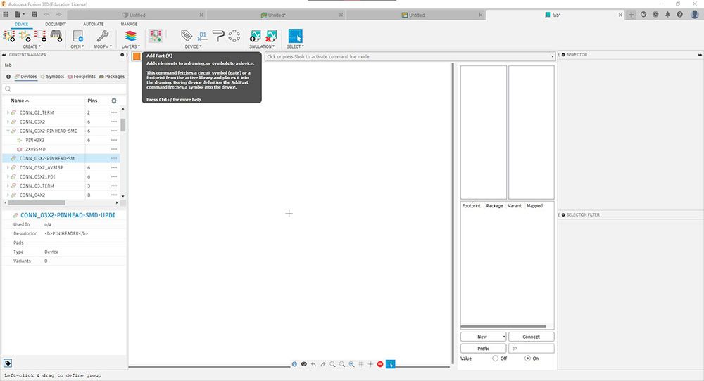

I editted the 2x3 connector so that we can use it in both orientations so we can connect our UPDI program to program the ciruit. We can edit the fab library in the library manager by clicking edit…

Since I wanted to use an existing component and edit it I duplicated an existing connector “CONN_03X22-PINHEAD-SMD” and named it “CONN_03X22-PINHEAD-SMD-UPDI“…

I then duplicated the symbol “PINH2X3” and renamed it “PINH2X3-UPDI” then deleted the existing pins and added 3 pins and renamed the pins


I also duplicated the footprint “2X03SMD” and renamed it “2X03SMD-UPDI“… which I later realised it wasn’t necessary…

Because I duplicated an existing component I needed to disconnect the exiting symbol and footprint so that I can connect it to the new symbol I created…
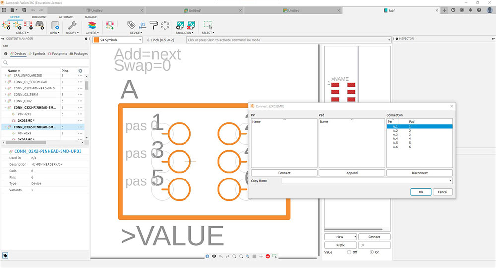

Now I can remove the existing symbol and footprint so I can add the new ones I duplicated…

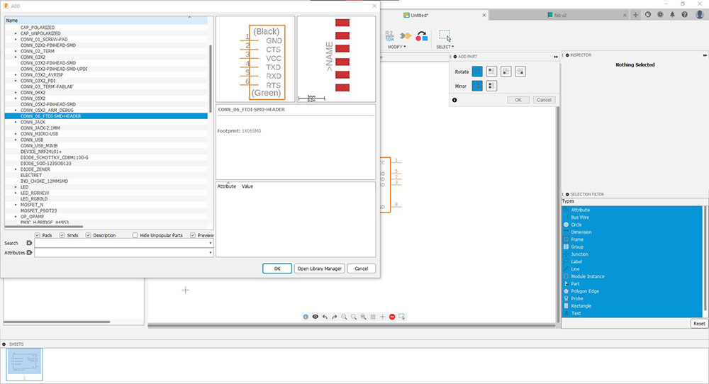
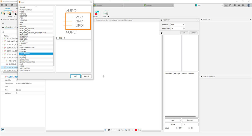
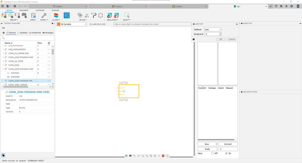
To add symbol I clicked “Add Part” then selected the symbol I duplicated and placed it on the workspace…
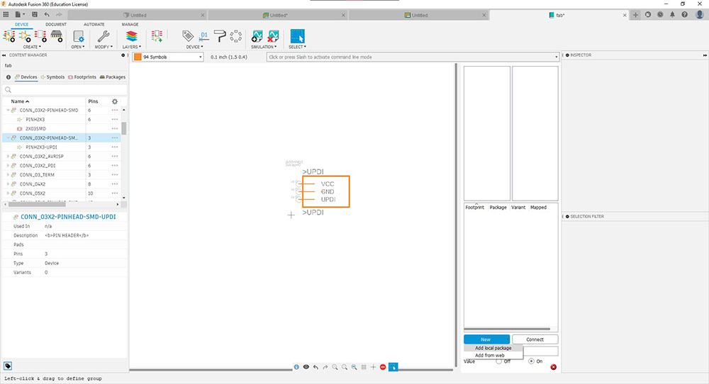
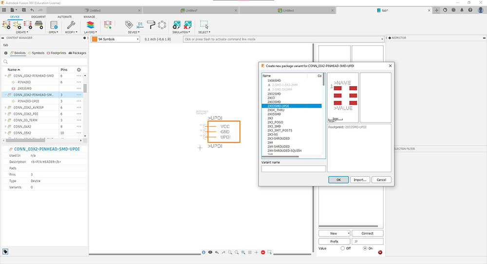
To add footprint I clicked “New” and selected “Add local package” and selected the footprint I duplicated…
Now we can connect them…
Now that we have editted the symbol we can add it in our schematic…

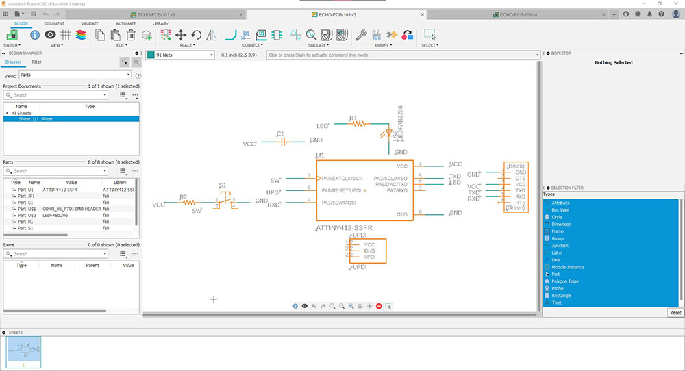
This is how it looks when we add all our parts for our circuit…

Then I arranged them, and added Net and Labelled them to their appropriate port…

Now we can switch to the PCB document where we can route the traces using the “Autorouter” which then simulates possible route maps…

 I got this trace after a bit of tweaking and turning
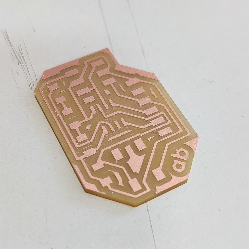
We can then switch off all the layers except the trace and export this as monochrome and send it for manufacturing
Production Phase
I milled it using the Roland MODELA MDX-20 and soldered the components to the board…


Since I didnt consider a resistor for the switch I was facing voltage leaking issues and a faulty button I redsigned and manufactured one more PCB…
 Redesigned product…
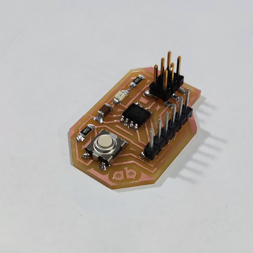 Finished product…
Now we can start programming…
Finished product…
Now we can start programming…
Programming Phase
Using Arduino IDE we can program our ATTiny 412 board but since Arduino IDE doesn’t have the ATTiny library I added it by going to “Preferences” under “File” drop down menu on the menubar

Beside “Additional Boards Manager URLs:” there is a button where we can then add the URL below:
http://drazzy.com/package_drazzy.com_index.json

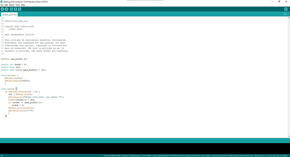
Now we can connect our FTDI board with our ATTiny board and upload the following code…
//
// hello.t412.echo.ino
//
// tiny412 echo hello-world
//    115200 baud
//
// Neil Gershenfeld 12/8/19
//
// This work may be reproduced, modified, distributed,
// performed, and displayed for any purpose, but must
// acknowledge this project. Copyright is retained and
// must be preserved. The work is provided as is; no
// warranty is provided, and users accept all liability.
//

#define max_buffer 25

static int index = 0;
static char chr;
static char buffer[max_buffer] = {0};

void setup() {
   Serial.swap(1);
   Serial.begin(115200);
   }

void loop() {
   if (Serial.available() > 0) {
      chr = Serial.read();
      Serial.print("hello.t412.echo: you typed \"");
      buffer[index++] = chr;
      if (index == (max_buffer-1))
         index = 0;
      Serial.print(buffer);
      Serial.println("\"");
      }
   }
Make sure the right Port is selected…

Now click the upload button…

Once it has finished uploading we can open the serial monitor and type in anything and the board will return it
 If the Serial Monitor isn’t responding or giving output then change the baud rate to 115200
I shall be programming it in the Embedded Programming week