8. Embedded programming
WEEK 8
This week’s assignments are:
- To read the data sheet for our microcontroller
- To use our programmer to program your board to do something
- To compare the performance and development workflows for other architectures(Group Assignment added HERE)
ATtiny412
In the past weeks we used a SAMD11C14A microcontroller for making our UPDI programmer and we used an ATtiny412 microcontroller for creating an echo hello-world board with an LED and a buton. This week we learn to program our board we made the previous week
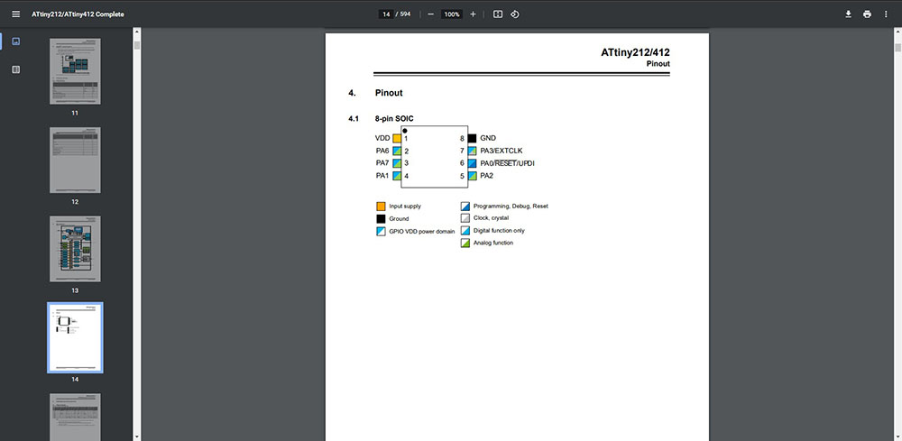
First we need to find the datasheet of our ATtiny412
From the DataSheet we know that ATtiny412 uses the AVR® architecture and that it can run at up to 20 MHz, with 2/4 KB Flash, 128/256 bytes of SRAM, and 64/128 bytes of EEPROM in an 8-pin package
If we dig deeper we can find out the Pinout…
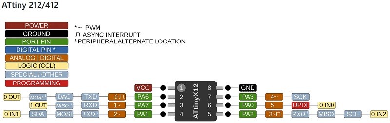
we’ll also need our Pin Mapping
ARDUINO IDE
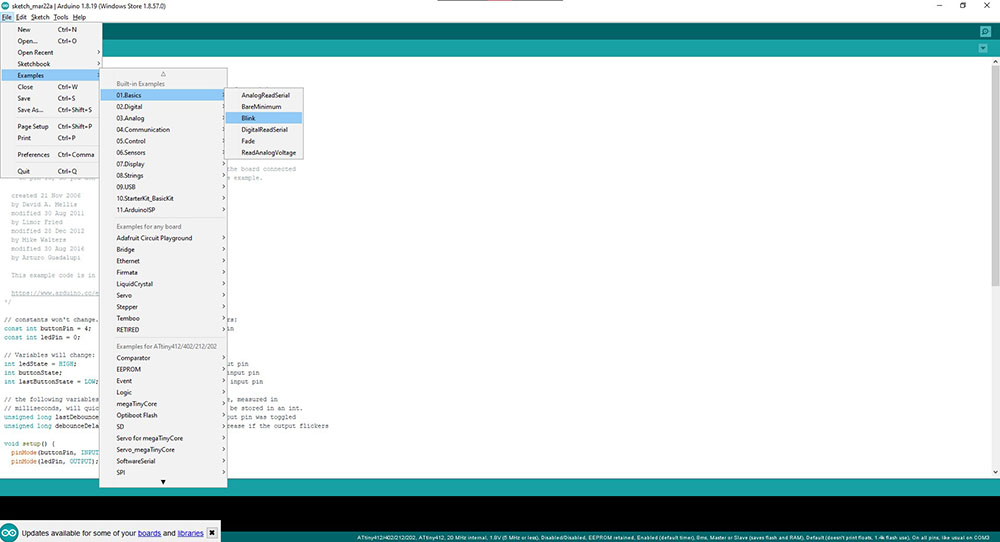
Using Arduino IDE we can program our LED and button using the existing examples and I started with the “Blink” example…
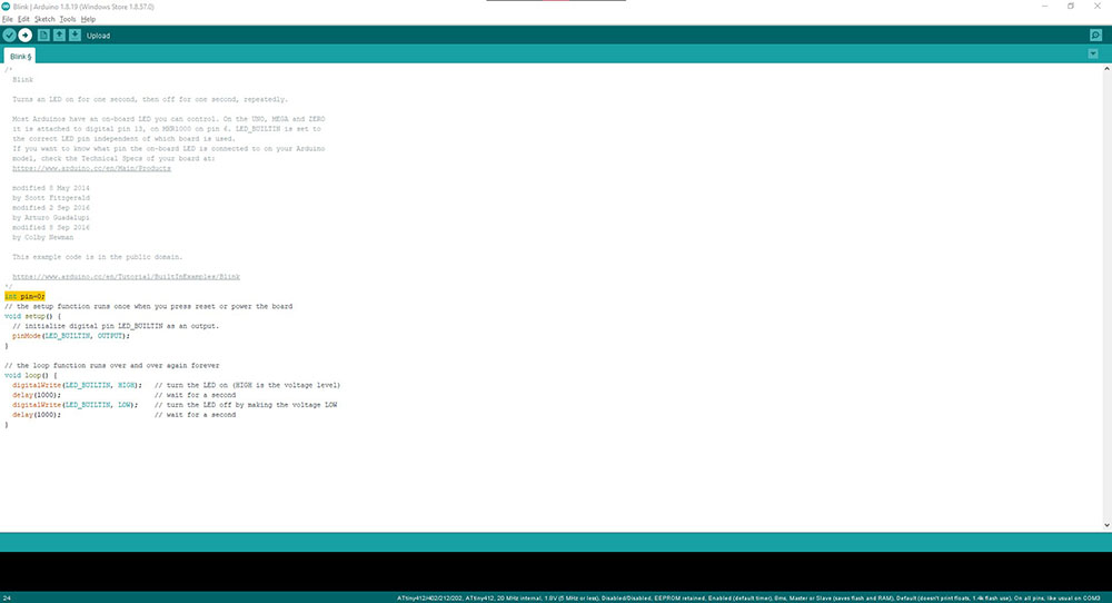
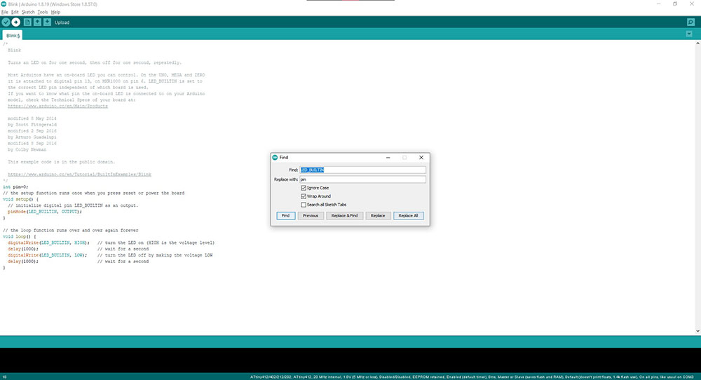
 Now since I made the board I know which pin is connected to LED but just to be sure I looked at the schematic and from the pinmap found out that the LED was connected to second pin whose value is ‘0’ so I intiated a new variable to store that value and replaced it with the example…
int pin=0;
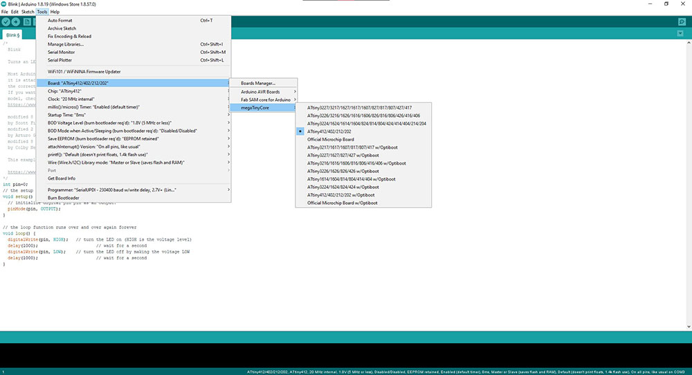
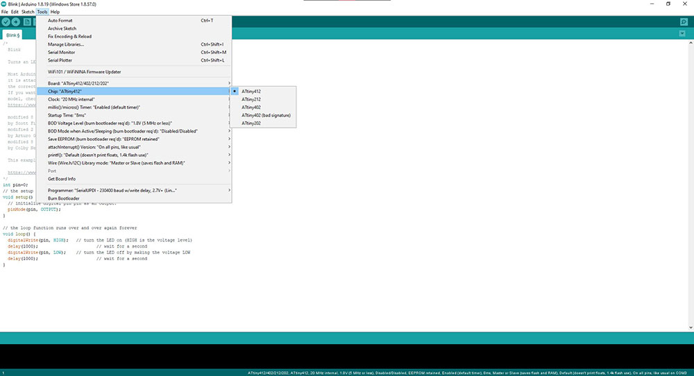
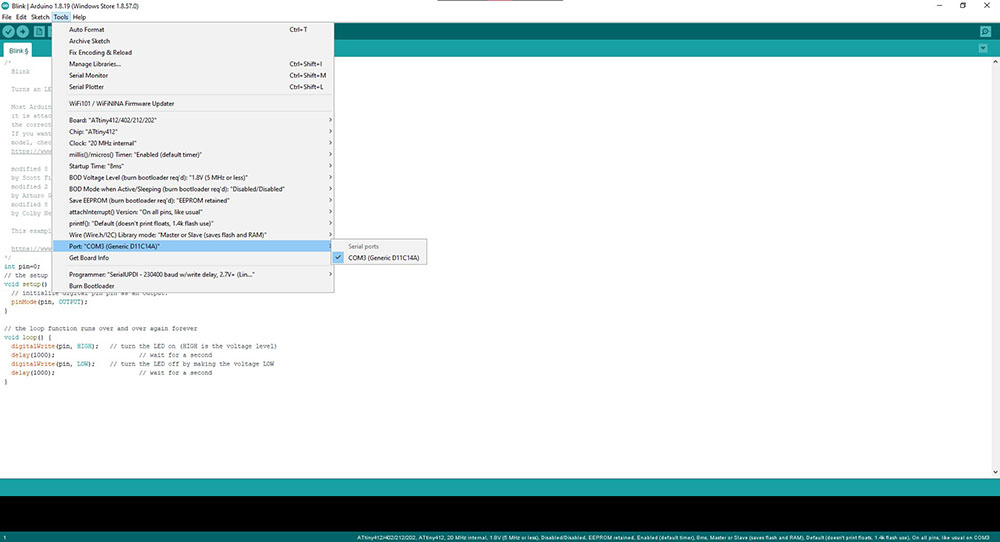
 To select our ATtiny412 from the “Tools” drop-down menu and select “ATtiny412/402/212/202” under “Board”>”megaTinyCore”, then under “Chip” we can select “ATtiny412”…
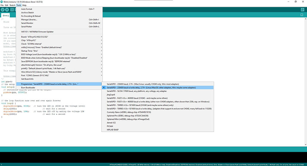
 Make sure we have selected the right “COM” port(in my case COM3) and the Programmer,
 And then we “Burn Bootloader” and then “Upload” button

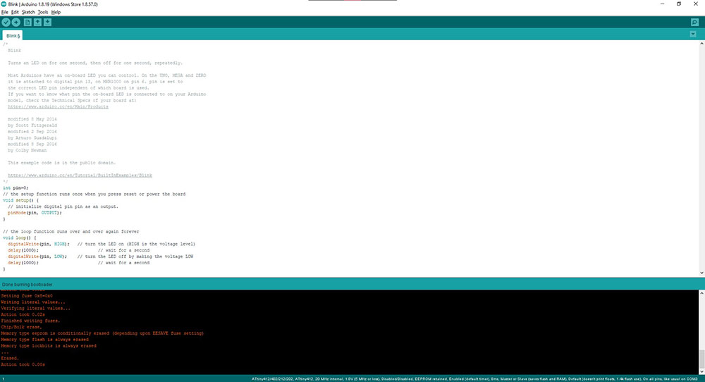 This program makes the LED blink with 1second interval(1000ms) using the “delay(1000)” function
Delay can be reduced according to how much time interval we want to give
Also tried the “Button” example…
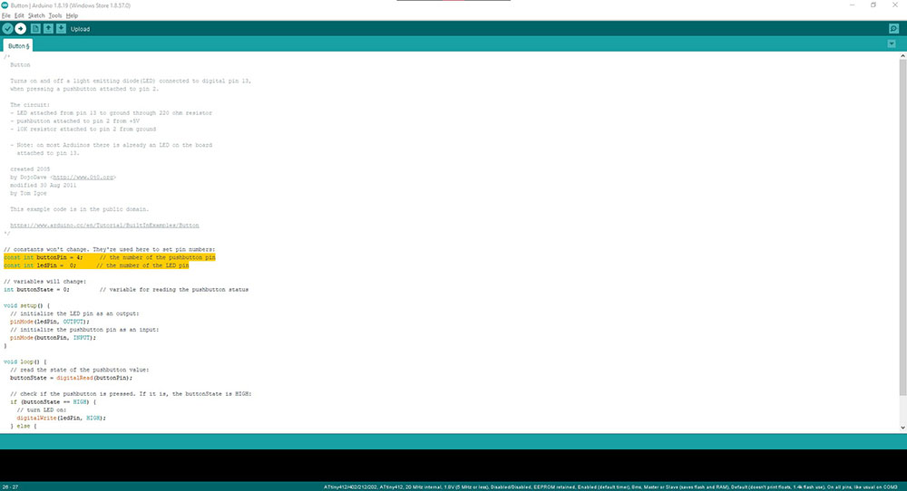
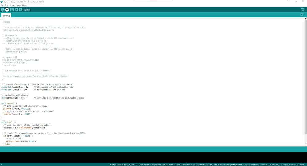 Here again we look at our schematic and pinmap to find which pin our switch is connected to and changed the given value and hit “Upload” …
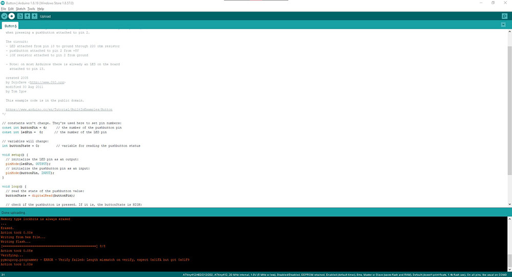
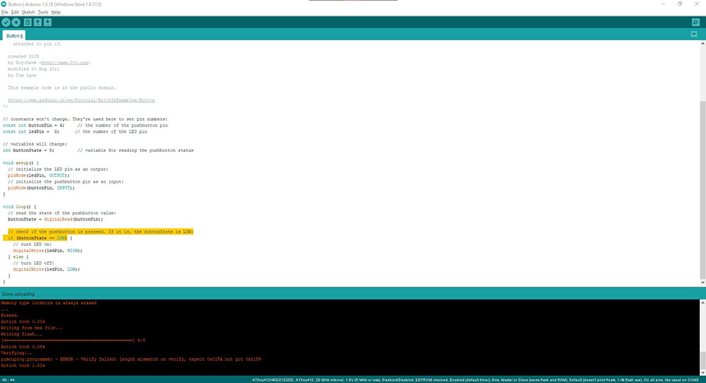
As we can see here, we have our light turning OFF while pressing the button and by changing the values from “HIGH” to “LOW” we can make the LED turn ON when the button is pressed…
if (buttonState == LOW)
Since the button should be held down in order to make the LED stay lit I figured we could do this if we store the value to a variable when the button is pressed and wrote a code
const int ledPin = 0;                           // for storing the value of the LED's pin
const int btPin = 4;                            // for storing the value of the Button's pin
int btState = 0;                                 // for storing the value of the Button's state i.e if pressed or not
int btPos = 0;                                  // for storing the value of the Button's position i.e if the LED should be on or off

void setup(){
    pinMode(btPin,INPUT);                       // for initiallising the button as an OUTPUT
    pinMode(ledPin,OUTPUT);                     // for initiallising the button as an INPUT
}

void loop() {
    btState = digitalRead(btPin);               // for getting value from the button pin

    if(btState == LOW){
        btPos += 1;                             // to change position 1 when the button is pressed
    }

    if(btPos > 1){
        btPos = 0;                              // to change position back to 0 if it exceeds 1
    }

    if(btPos == 1){
        digitalWrite(ledPin,HIGH);              // to turn LED ON
    }
    else{
        digitalWrite(ledPin,LOW);               // to turn LED OFF
    }
}
Also tried adding a delay to have a time interval for each time it loops…
delay(100); // to add a delay between each loop
Since this code wasn’t perfect as the button was taking too many signals when pressed, with the help of Shahin we developed this code…
const int ledPin = 0;                           // for storing the value of the LED's pin
const int btPin = 4;                            // for storing the value of the Button's pin

bool btState=0;                                 // for storing the value of the Button's state i.e if pressed or not
bool btPos =0;                                  // for storing the value of the Button's position i.e if the LED should be on or off


void setup(){
    pinMode(btPin,INPUT);                       // for initiallising the button as an OUTPUT
    pinMode(ledPin,OUTPUT);                     // for initiallising the button as an INPUT
}

void loop() {
    if(!digitalRead(btPin)){                    // for checking if button pin input is not "HIGH"
        if(!digitalRead(btPin) && btState){     // for checking if button pin input is not "HIGH" and to check if button state is 1
            btPos = !btPos;                     // for changing value of button position to the opposite value (i.e, 1 to 0 or vice versa)
            btState = 0;                        // for changing value of button state to 0
        }
    }
    else{
        btState = 1;                            // for changing value of button state to 1
    }

    if(btPos){                                  // for checking if button position is 1
        digitalWrite(ledPin,HIGH);              // to turn LED ON
    }
    else{
        digitalWrite(ledPin,LOW);               // to turn LED OFF
    }
}
This way the button positon is stored away and wont change until the button is pressed again
MICROCHIP STUDIO
I also tried Microchip Studio to get used to the other environments
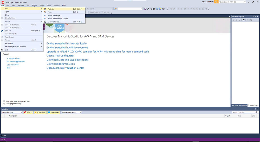
So I started by creating a new project from File>New>Project…
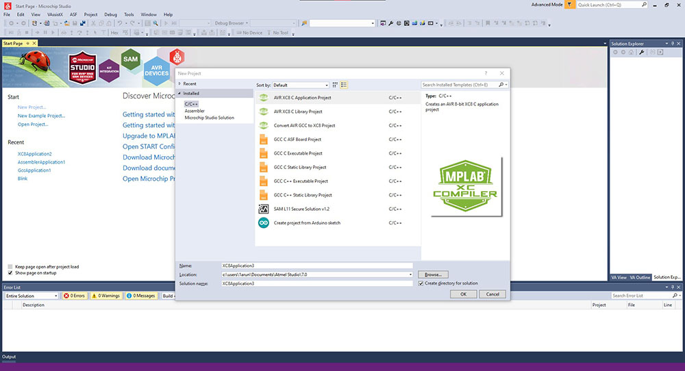
“AVR XC8 C Application Project” will be selected by default which we will be using for now…
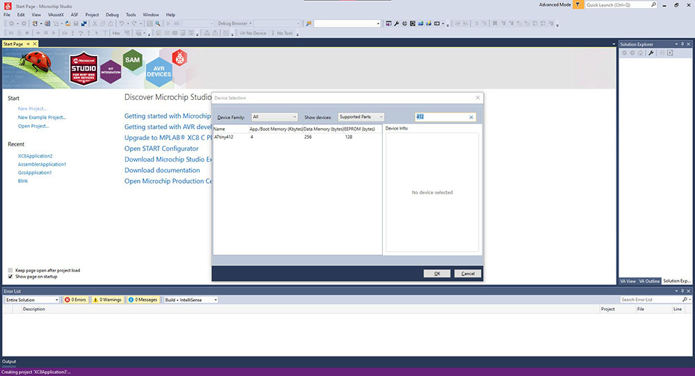
A window will pop up asking to select which board we are going to program where we can search for our microcontoller or we can just type in “412” in the search bar on the top right of the window and select it on the results…
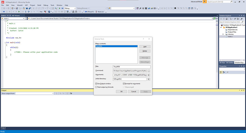
Since we are going to use our own UPDI board which we made the previous week we must add it as an external tool so that Microchip Studio can identify it, to do so we first install pyupdi from here
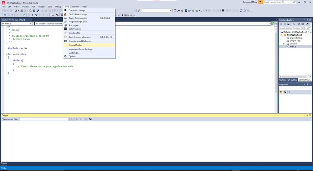
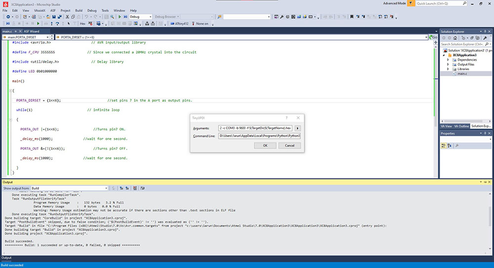
Now we can click “External Tools…” under “Tools” in the menubar which opens a window where we can click “TinyUPDI” and beside the “Command:” textbox click the “…” button and go to where we installed pyupdi and open “pyupdi.exe” …
Now add the following code in ‘Arguments:’…
-d tiny412 -c COM3 -b 9600 -f $(TargetDir)$(TargetName).hex
Make sure the right COM Port is selected
To find your COM Port just search for device manager in the start menu where you can see the COM Port to which you have connected to
And add the following code in ‘Initial direcory: and we can click ‘Apply’…
$(TargetDir)x
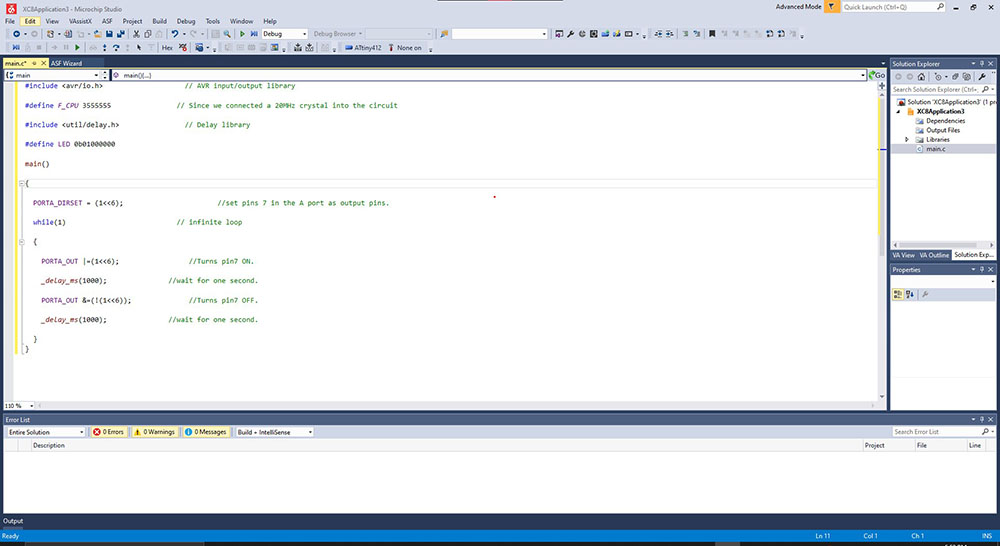
And now we can write our code in Embedded C
#include                     // AVR input/output library

#define F_CPU 3555555                // Since we connected a 20MHz crystal into the circuit

#include                 // Delay library

#define LED 0b01000000

int main()

{
    PORTA_DIRSET = (1<<7);                       //set pins 6 in the A port as output pins.

    while(1)                           // infinte loop

    {
        PORTA_OUT |=(1<<7);                 //Turns pin6 ON.

        _delay_ms(1000);               //wait for one second.

        PORTA_OUT &=(!(1<<7));              //Turns pin6 OFF.

        _delay_ms(1000);               //wait for one second.

    }
}
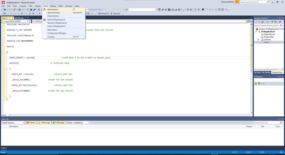
Now we can click “Build Solution” under “Build” on the menubar…
Once it is done now we can upload it to our board by clicking “TinyUPDI” under “Tools” in the menubar and then by hitting “OK” we begin to upload into our board
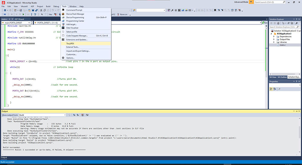
 Always a good habit to check COM Port
Output