11. Input devices
1. Weekly Brief Summary
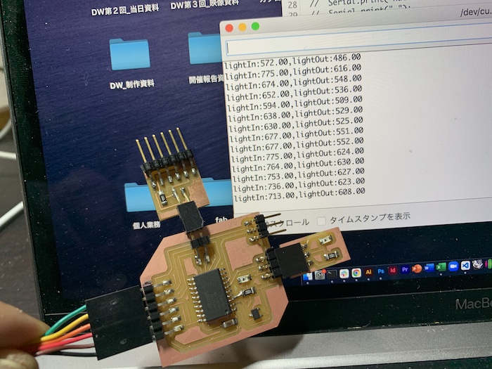
I made input device board including Hall sensor and light sensor, and detect its values.
2. Weekly Assignment Requirement
Group assignment:
- Probe an input device(s)’s analog and digital signals
- Document your work (in a group or individually)
Individual assignment:
- Measure something: add a sensor to a microcontroller board that you have designed and read it.
3. Group Assignment
FabLab KAMAKURA 2021 Lab site / input devices
4. Items
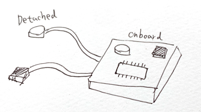
I decided to use 2 sensors (Hall / Light), on 2 other places (Onboard / Detached).
Micro Controller / ATtiny3216
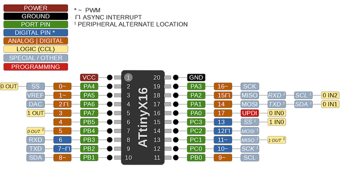
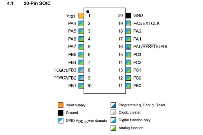
From datasheet, there are enough analog pin for this week. Without pins for RX, TX, UPDI communication, I can use 11 analog/digital pins, and 4 digital pins.
Hall Effector / A1324LLHLT-T
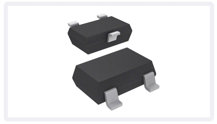
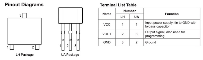
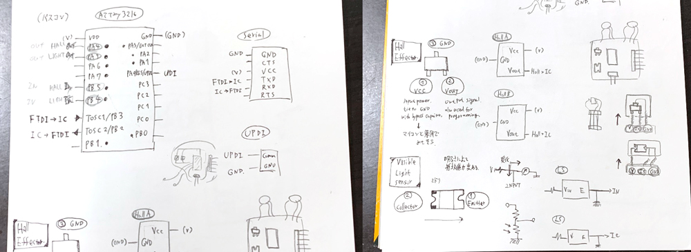
Hall effector shows analog value depends on surrounding magnetism. It has 3 pins, one is from VCC, another is for GND, the last one outputs signal, shoud be connected IC.
Light Sensor / PT15-21C/TR8
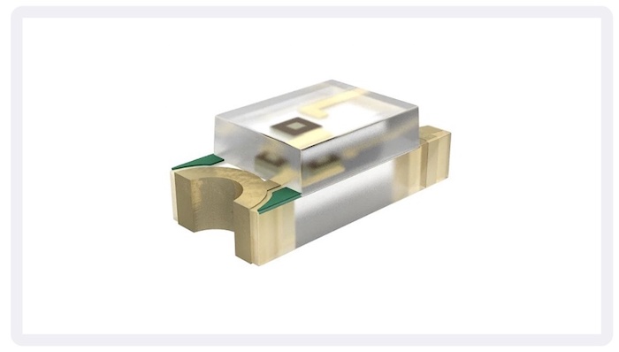
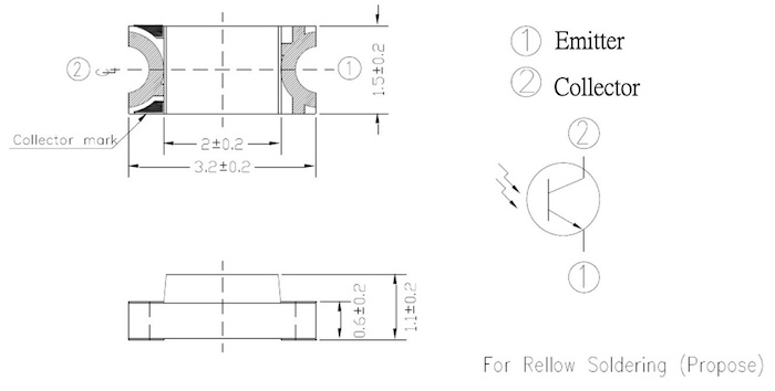
Visible light sensor chages its resistance value depending on surrounding lights. This sensor has 2 terminal, one is collector, pointed by green ink, the other is emmiter. Current must be flown collector to emitter.
I checked Neil’s sample board, and sketch for thinking connection.
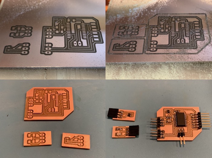
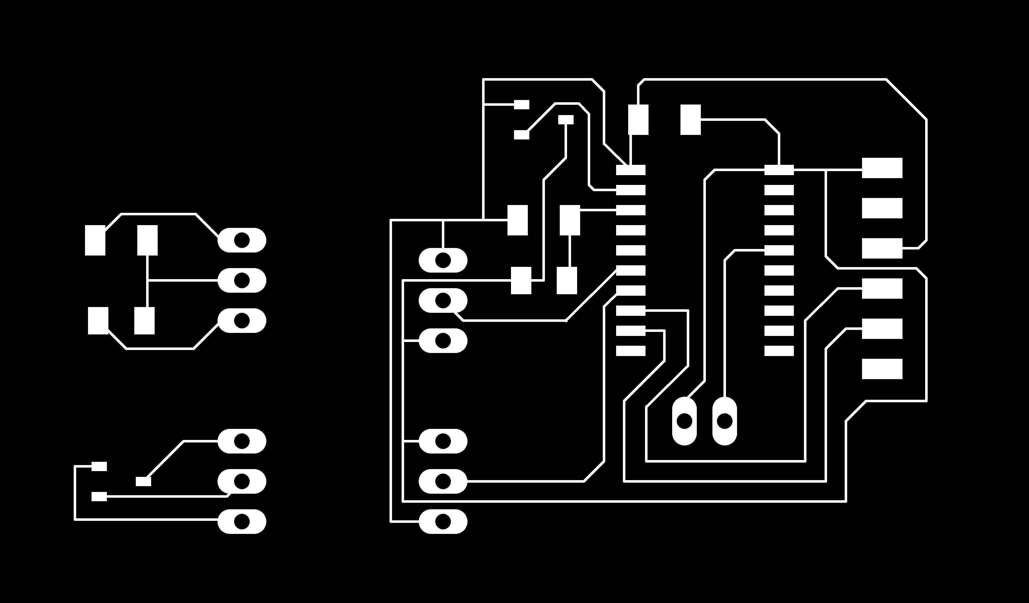
5. Design and Make Board
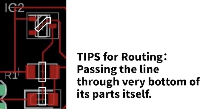
As the number of parts increases, so does the difficulty of the design. I found good technique for routing, passing the line through very bottom of its parts itself.
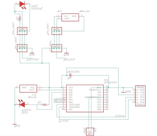
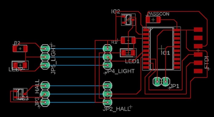
※ I used blue(bottom) line for simulate connection between detached boards and main board.
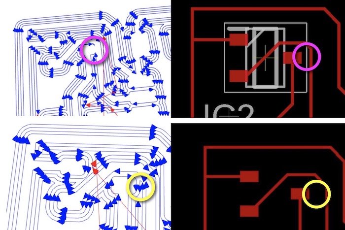
Even though I checked design rule, processing simulation did not work well on some part because of the thin lines. I made it more wide and fixed.
| Parts Name | Quantity |
|---|---|
| ATtiny3216 | 1 |
| 1uF Capasitor | 1 |
| 6 pin connector/FTDI | 1 |
| 2 pin conncetor/UPDI | 1 |
| 3 pin male connector | 2 |
| 3 pin female connector | 2 |
| Hall Effector | 2 |
| Light Sensor | 1 |
| 10kΩ Resistor | 2 |
6. Programming and Measuring
int HALLin = 0; // PA4
int LIGHTin = 1; // PA5
int HALLout = 5; // PB4
int LIGHTout = 4; // PB5

void setup() {
  Serial.begin(115200);
  pinMode(HALLin, INPUT);
  pinMode(LIGHTin, INPUT);
  pinMode(HALLout, INPUT);
  pinMode(HALLin, INPUT);
}

void loop() {
  float hallIn = analogRead(HALLin);
  float lightIn = analogRead(LIGHTin);
  Serial.print(hallIn);
  Serial.print(",");
  Serial.println(lightIn);
}
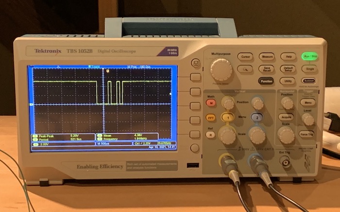
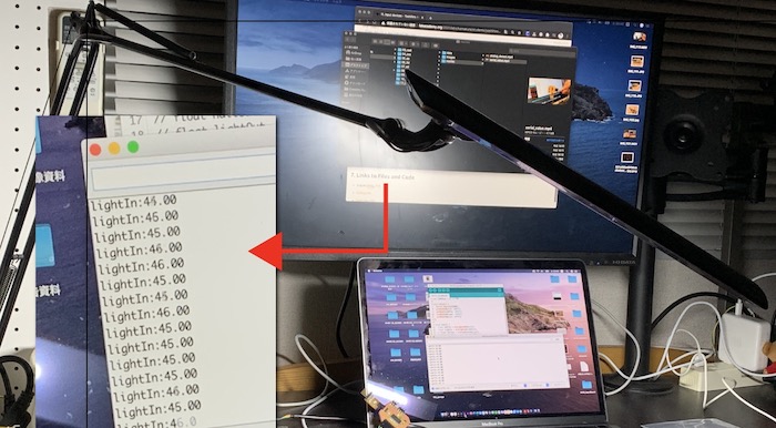
In my house, light types effects sensor value !
In case of desk light, value is stable.
In case of cealing light, value is unstable.
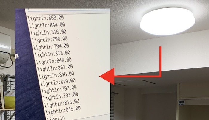
Two sensor value is not same, need adjust by programming or board design.
7. Links to Files and Code
- EAGLE schematics
-
EAGLE board
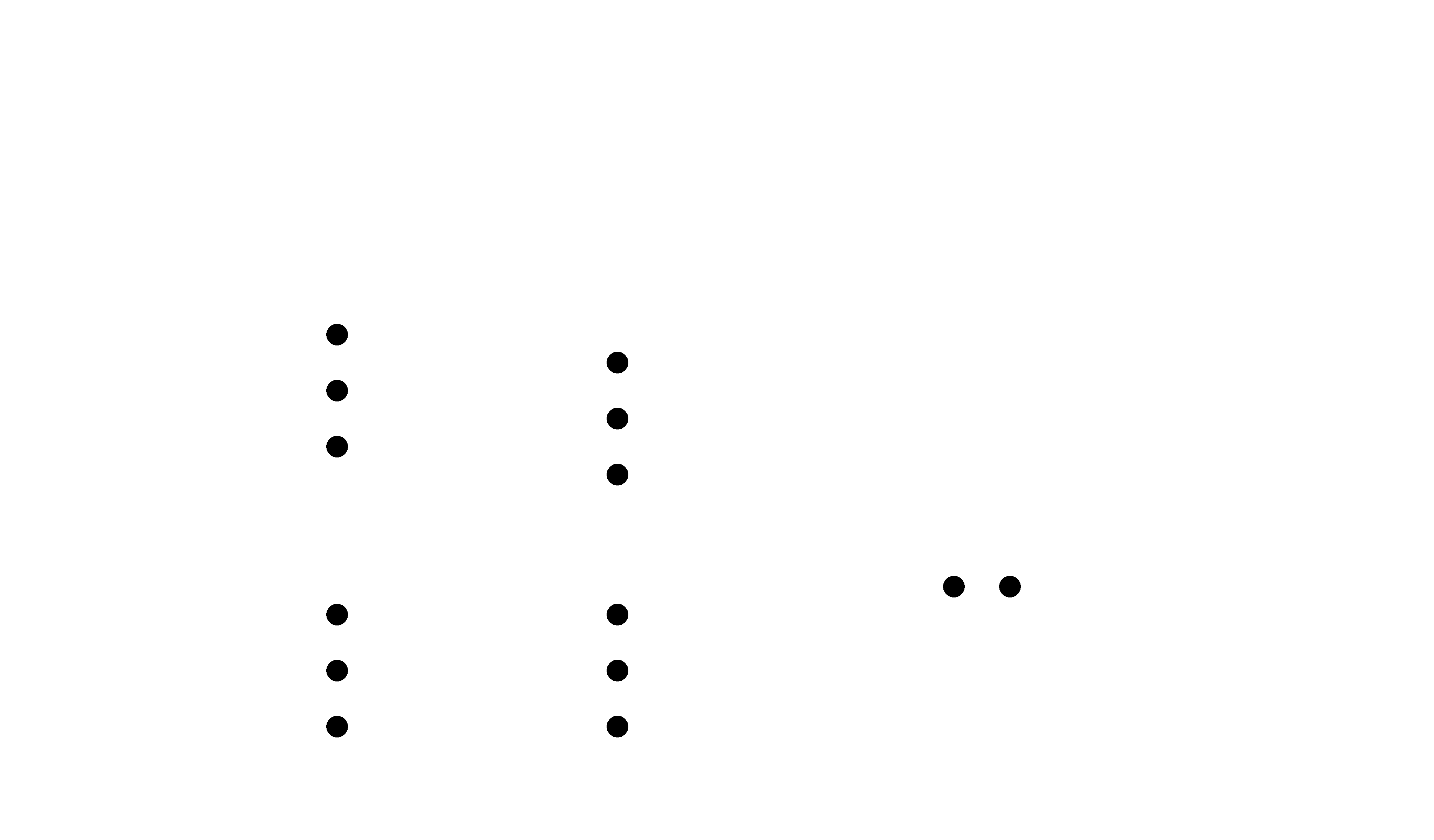
- holes png,rml
-
Arduino Sketch InputDevices.ino