8. Computer-Controlled Machining
1. Weekly Brief Summary
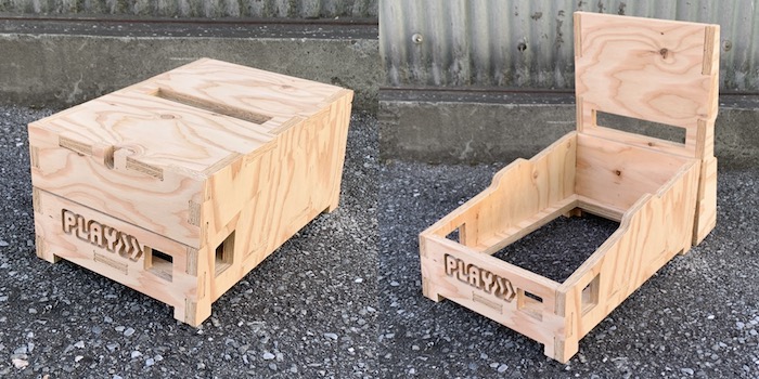
Using ShobBot and V Carve Pro to cut an 18mm thick wooden board to make a pinball machine housing.
2. Weekly Assignment Requirement
Group assignment:
- Test runout, alignment, speeds, feeds, and toolpaths for your machine
- Document your work (in a group or individually)
Individual project - Make (design+mill+assemble) something big
3. Group Assignment
FabLab KAMAKURA 2021 Lab site / Comupter-Controlled Machining
4. Basic Modeling
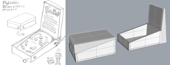
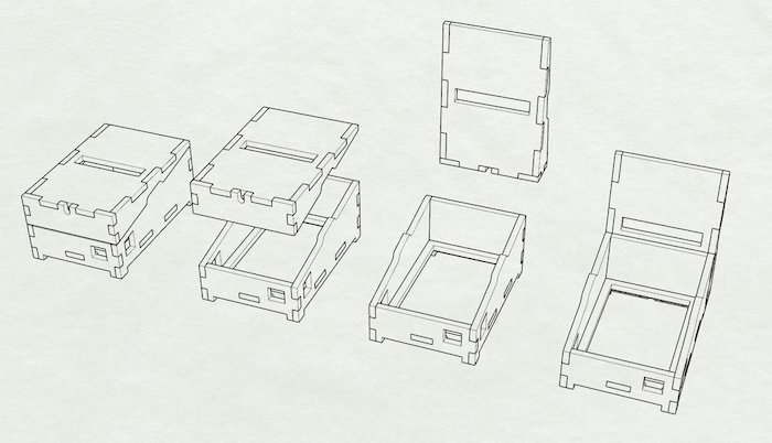
I Made a chassis for the pinball game I will be making for the final project. I haven’t designed the inside in detail, I will only make the basic shape this week by drilling holes for the electronics and joints.
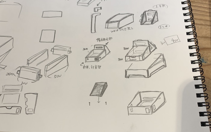
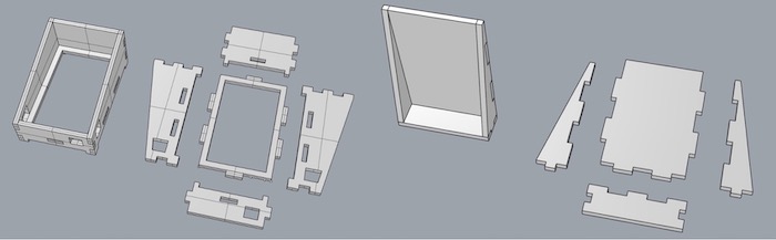
Modeling in Rhinoceros based on 18mm thickness. There are two ways to combine them: zigzag assembly and convex/concave. In the end, I plan to put a cover on the top.
The first step is to make a simple model and check the size. Since I wanted the model to be able to open and close, I also considered the angle of the diagonal.
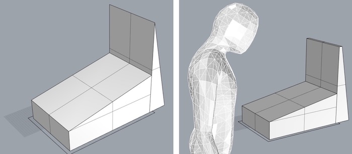
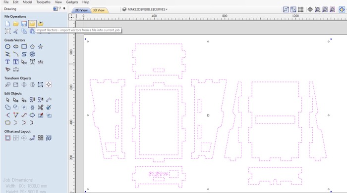
The completed shape, taking into account the unevenness, is made into a flat surface using Make2D and placed so that it fits into a board of 1800mm*900mm.
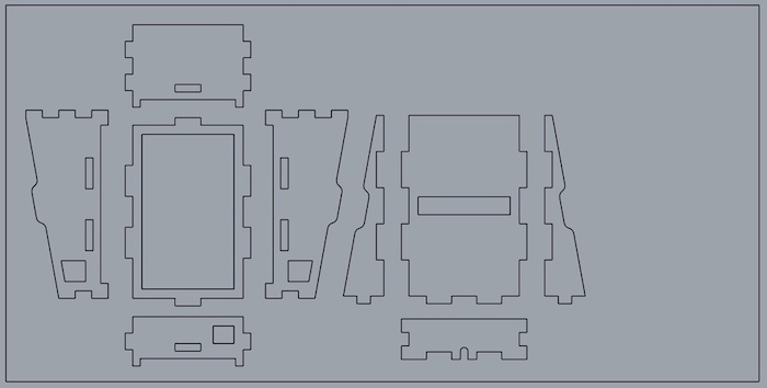
After making 2D data, I used CAM tool, V-Carve Pro for making processing data.
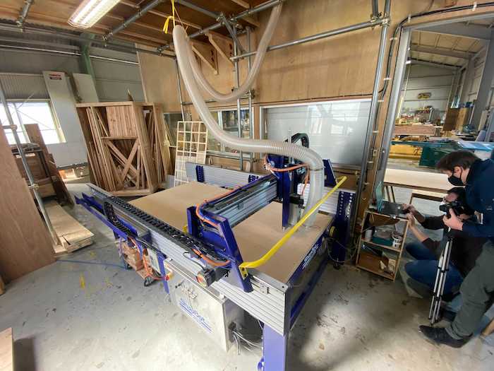
5. Test cut by Shpopbot
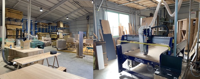
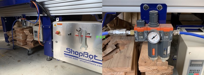
The basic usage of Shopbot is as follows.
- Turn on the main unit.
- Move the spindle to the appropriate position.
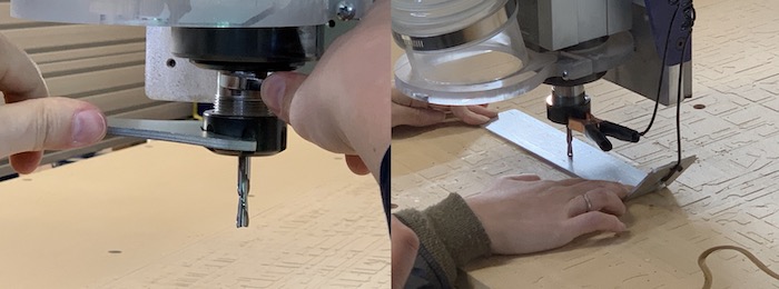
- Attach the collet and end mill.
- Set the origin of XY axis and Z axis.
- Use Shopbot3 and check the behavior in Preview.
- Select “3D Offset” in Move/Cut mode and check the operation.
- Select “No offset” in Move/Cut mode.
- Turn on the dust collector and spindle, and start machining.
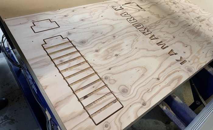
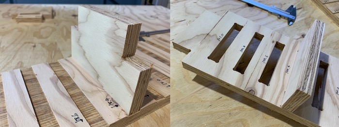
In order to find the right offset value, a test piece was machined with different widths of 0.2mm each. In this time, we use 18mm-thick lumber plyawood. We found that an offset value of +0.2 to 0.4 mm for height and +0.4 mm for width in total was just right.
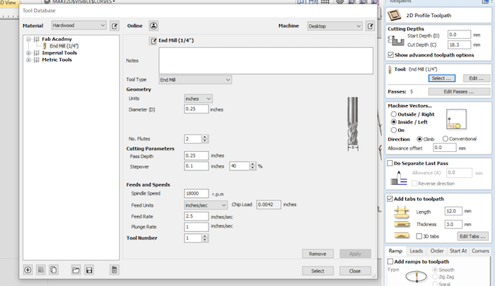
Processing Condition
- Tools : Solid Carbide router, 2 flute, downcut extreme heavy duty
- Feed Rate : 2.5 inches/sec
- Spindle RPM : 18000
- Cut Depth : 18.3mm ( 18 mm material thickness + 0.3mm over cut)
- Step Depth : 4.575mm (4 times cut for 18.3mm)
6. Edit Toolpath
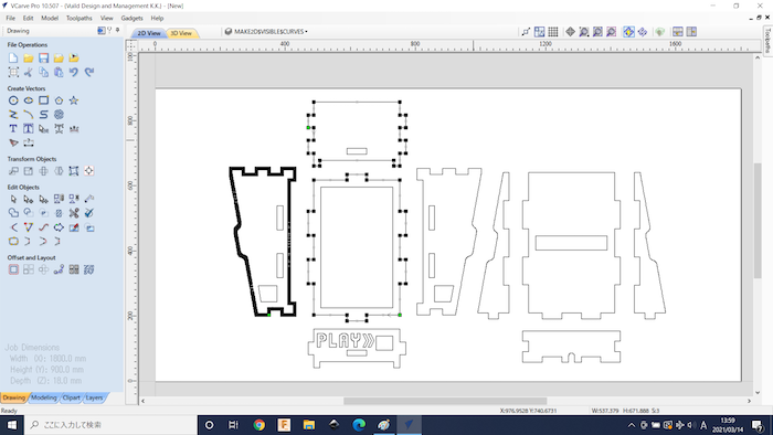
For making data for ShopBopt, I used V-Carve Pro.
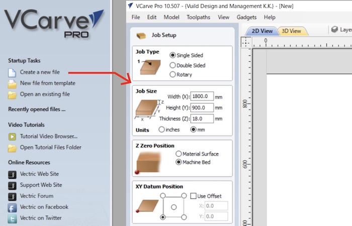
Select create a new file and set material information. In this time, Job Type is Single Sided, Job size is Width = 1800mm, Height = 900mm, Thickness = 18.0mm, Z zero position is on Machine Bed. After material settings, let’s import vector file on V-Carve.
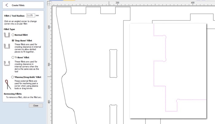
In order to create a clean right angle, fillets need to be added in some places. I added Dog-Bone Fillet by clicking edges.
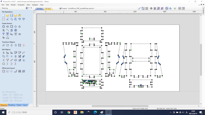
When I opened the exported dxf file in Adobe Illustrator, added text, and then exported another dxf file and opened it in V Carve Pro, the display was a little strange. There were a large number of nodes placed outside of the anchor points, and some of them were out of place, so I couldn’t add fillets properly.
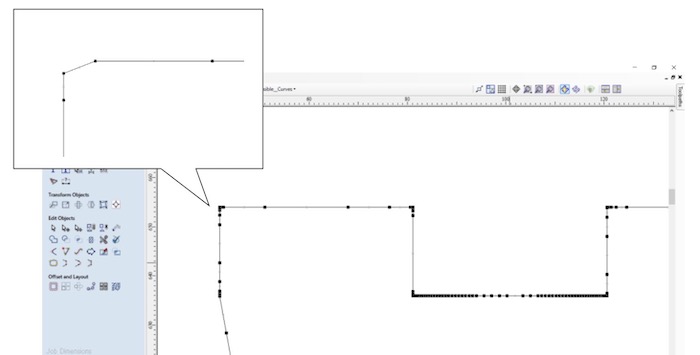
Although we could erase the nodes directly, we considered Bell’s method because of the huge amount of work involved and the uncertainty of accuracy. In the end, the error was resolved by directly importing the Adobe Illustrator file in V Carve Pro.
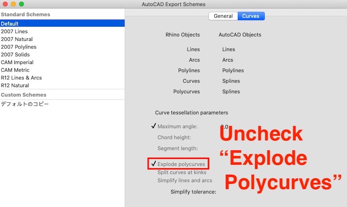
【Advice】In Asian Review, Saverio shared me tweaks of dxf for Rhinoceros.
When you export as DXF you make sure the polycurves are all closed. You have to select the objects to export, go to EXPORT SELECTED> choose DXF > OPTIONS > EDIT SCHEMES, and deselect the EXPLODE POLYCURVES option. Select the following (create a new profile):
There are some types of cut settings, Drilling Toolpath for just making hole, its diameter is same as bit , 2D Profile Toolpath for cutting through(or not) and more. When I use 2D Profile toolpath, need to select the way machine will move traced Outside/Inside/On vectors. I set Outside for the outermost line of each part, Inside for holes. Also need to set tabs by checking Add tabs to toolpath, not to each part fly or move out after cutting apart.
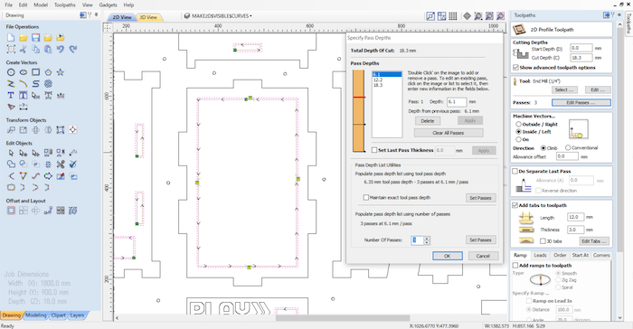
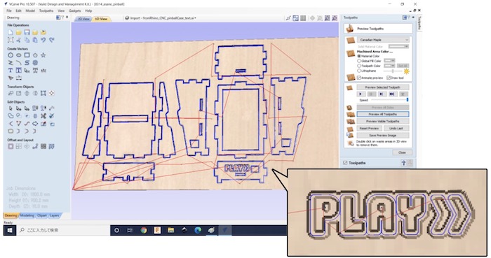
Since the visibility of the text could not be checked with any other tool, I made several adjustments with V Carve Pro to determine the final shape.
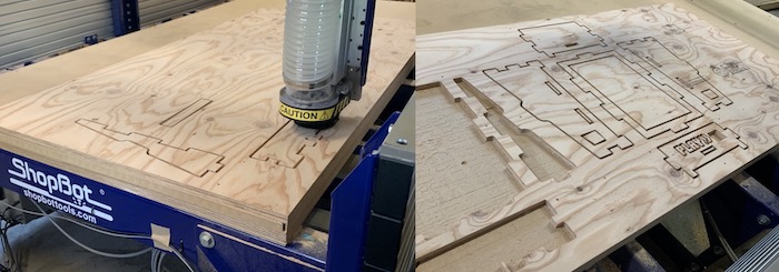
7. Cut by ShopBot
After fixing toolpath, I cut the parts by ShopBot. I used same processing condition as test cut.
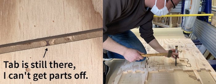
Tabs need to be the right size for each part to be processed. Small parts without tabs will be sucked up by the dust collector or change position and interfere with the machining path. When the tabs are still firmly in place, I used a chisel to remove them after I’m done processing with Shopbot.
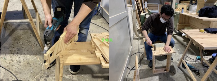
The parts that has just been machined may have a rough surface or tabs left on it. Hand tools are used to finish the surface. In this case, the offset value I checked in the test cut was just right, and I was able to fit them together with just the right amount of force.
8. Links to Files and Code
Files
- asano_pinball_housing.3dm
- asano_pinball_housing.dxf
- asano_pinball_housing.crv
- 01_drill.sbp
- 02_backsideCut.sbp
- 03_frontsideMillCut.sbp