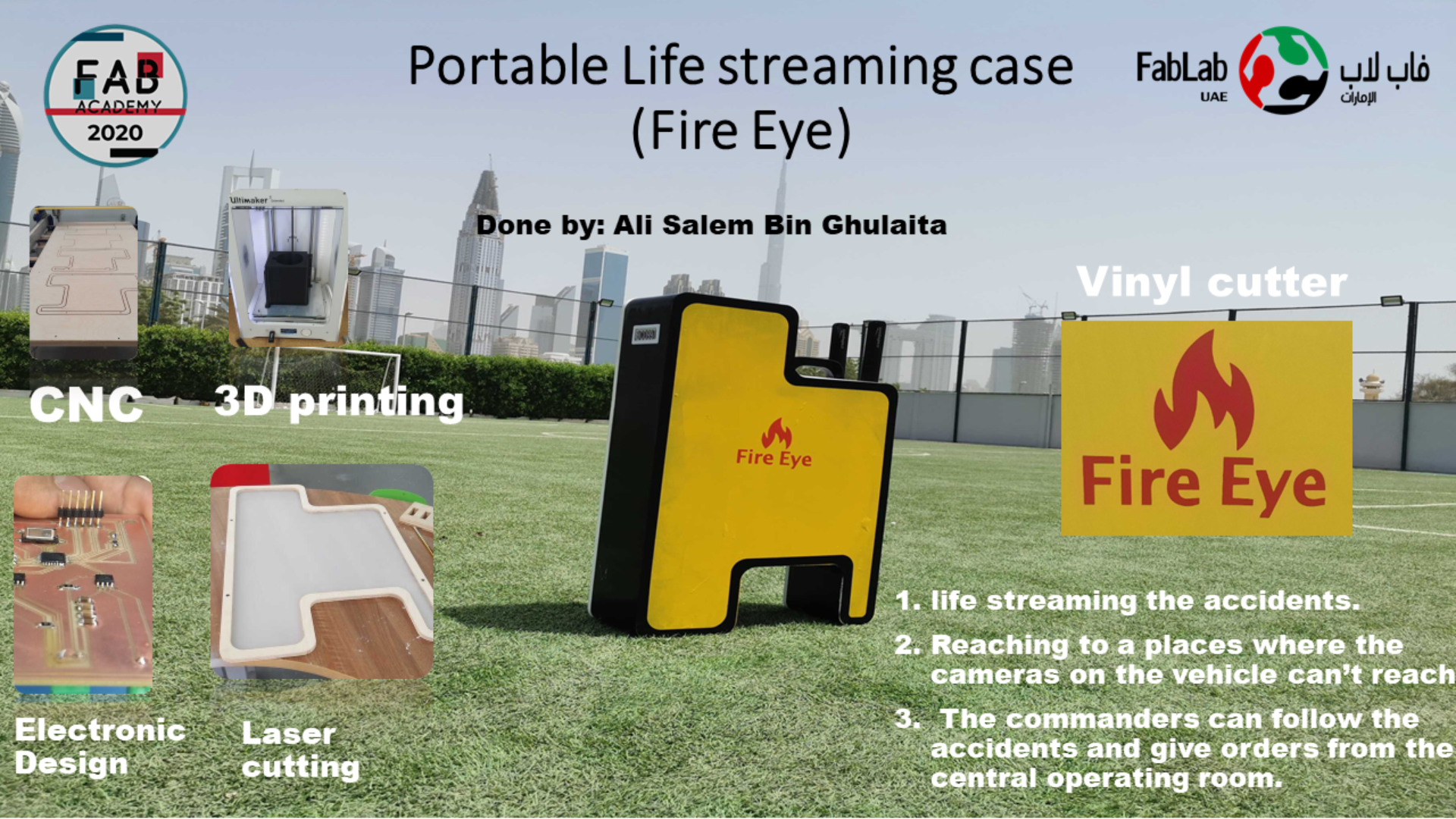
Final Project Fire Eye
This week I worked on defining my final project idea and started to getting used to the documentation process.
Questions to answer
What will it do?
We can use the portable life stream case for covering the accidents from all sides. The commanders will have full view on the accidents to run and give the right orders. The video will be taking from the accidents will also help in investigations after the accidents. It helps the trainees before going to the field and facing a real accident. Gives accurate and real time intelligence as to the progression of the fire spread.
Who’s done it beforehand?
There were phones that show livestream videos through apps but in my experience I never saw a livestream case being made and used.
What will you design?
I need to design a case that is portable in size and you can fit it in your vehicle and has support where you can hold it and carry it around. It also needs an arched stand that you can hook in the vehicle so you can film without the case moving in place.
What materials and components will be used?
-
Modem
-
12V 15000mAh li-ion battery
-
Rotatable Camera
-
Circuit board that battery checker (RGB LED lights, buzzer, cover for the LED made by 3D printer)
-
Aluminum 3 inch Tube
-
Tube foundation to hold the tube in the case.
-
Wires
-
Switch
-
Battery charger
-
Assembling parts (Screwdriver and nut)
-
Battery mold
-
Camera foundation
-
Acrylic pieces for covering the design inside of the case.
Where will they come from?
-
I will buy the components and materials online or locally. I will fabricate some materials by my own in the FabLab.
-
Tube, stopper motor, wood, electronic components, RGB Light: FabLab.
-
Camera, modem, battery: Online purchase.
How much will they cost?
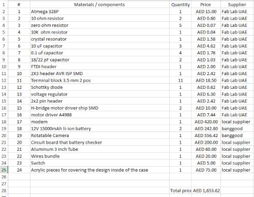
Total amount 1653.62
What parts and systems will be made?
I will make most of the components in the lab
-
The portable case
-
Camera foundation
-
Tube holder
-
Board
-
Motor Driver
What processes will be used?
1-3D designing and printing - The camera holder.
2- Electronics design and fabrication - designing the main board using Eagle, then fabricating using flatcam and roland.
3-3D designing and milling - designing the case, and fabricating it using the shopbot.
4- Laser cutting - used laser to cut acrylic pieces for covering the design inside of the case.
5- Electronics integration and programming - connected the inputs and outputs to my board, integrated the camera and the motor and programmed the RGB LED.
What questions need to be answered?
Checking whether the signal from my portable case camera is working properly from my location to the operation room of the Civil Defense. I want to see if the camera can show both video and sound properly so the operation room can see the incident clearly.
How will it be evaluated?
First I carry the case to the place I want to film, then I switch it on. The camera will come out of the case and the modem will take 5-10 seconds to turn on the LTE in the SIM card and all systems will switch on. The camera will start live streaming and sending the video to the Dubai Civil Defense Operation Room where they can watch the video live.
What are the implications?
We can use the portable life stream case for covering the accidents from all sides. The commanders will have a full view on the accidents to run and give the right orders. The video will be taking form the accidents and will also help in investigations after the accidents. It helps the trainers before going to the field and facing a real accident. Gives accurate and real time intelligence as to the progression of the fire spread.
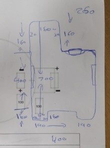
Planning and Sketching
I started my final project by making a sketch with the measurements as shown below. While making the final project and sketch I had these points in mind:
-
It must save space in the vehicle.
-
It is designed to have a curved space for 4 cases to fit in one stand that allows it to be positioned in any place and record without any problem.
-
It should have free space inside the case to prevent any damage to the camera.
-
It should have more space for the battery to extend the time for it to stay working.
-
The sides should be made of acrylic matte that helps show the color of the LED.
 )
)
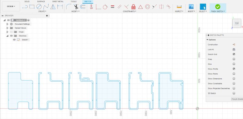
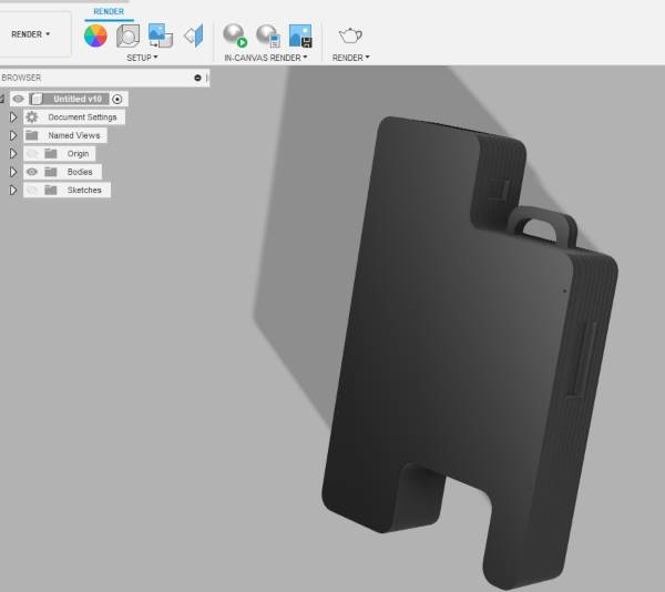
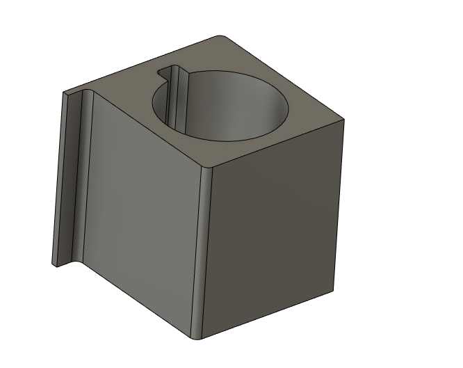
To start the designing process, I first drew a simple sketch to determine the general shape. I chose this design, because I think the case will be easily stored in the car and moved to be carried and used for the civil defense. Moreover, the curves in the case are desiged to be milled and assembled neatly. My aim is to create single frames then attach them together to create the case altogether. I designed the sketch in mind using fusion 360 as shown below:
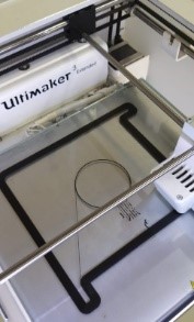
I made a model scale to test my project Using the laser machine and its scale .
After I made a rough sketch of the project, I started to draw on Fusion and I have designed 6 different parts for the case and later I will glue them together.
Plywood Case:
 )
)
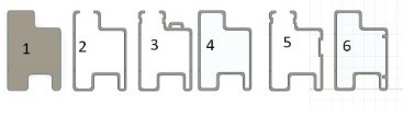
1- Full plywood case
2- Border made of plywood with an opening for the camera.
3- Border of plywood with flash, an opening for the camera, and a holder for the case.
4- Closed border of plywood to add acrylic inside the frame.
5- Border of plywood with an opening for the camera and an opening for controlling the switches of the case.
6- Closed plywood border with magnetic door.
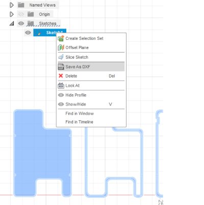
I prepared the design for milling by projecting each of the 2D shapes, and then saving the sketches as DXF files.
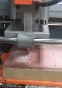
I placed the settings onto the shopbot machine and created the toolpath for cutting using vcarve, to fabricate the parts for my case. For the settings please see my computer controlled machining page
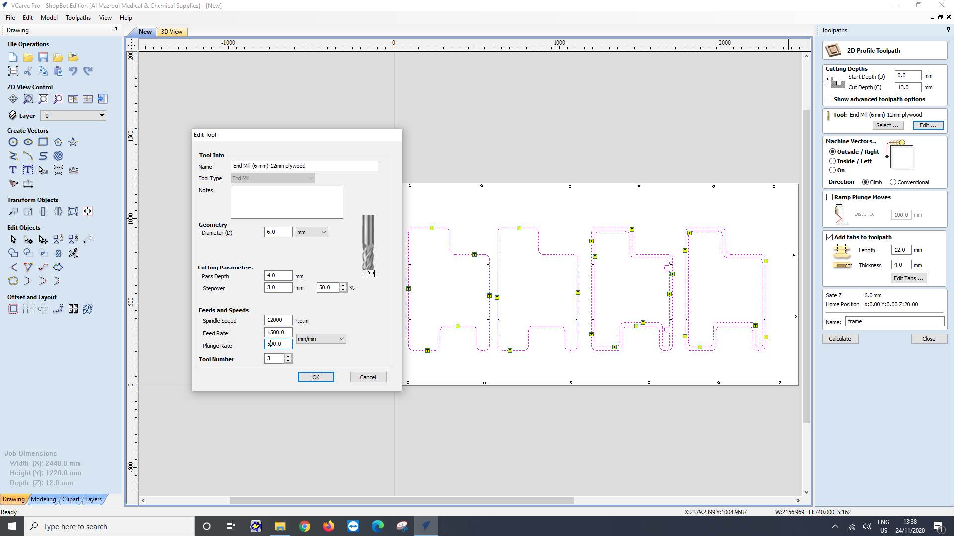
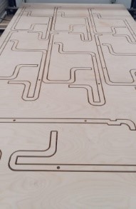
After inputting the settings onto the shopbot machine and it started cutting the parts for my camera. for the settings please see my computer controlled machining page
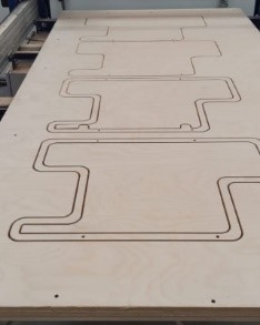
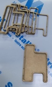
The machine finished cutting the main parts for my project and now I have to snap off the pieces and align them together in the pictures below.
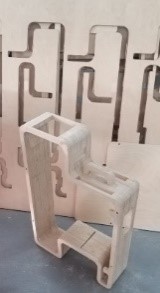
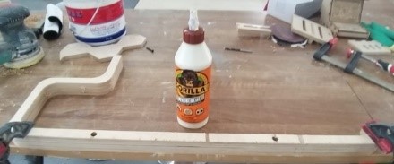
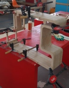
I started assembling the pieces together and sticked them.
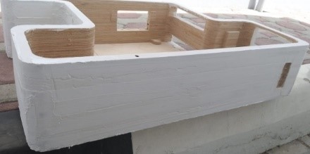
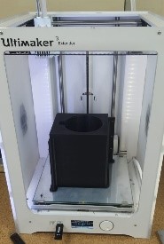
I have applied primer on my plywood and after it I have painted it white and the end product is shown below.
Electronic Work
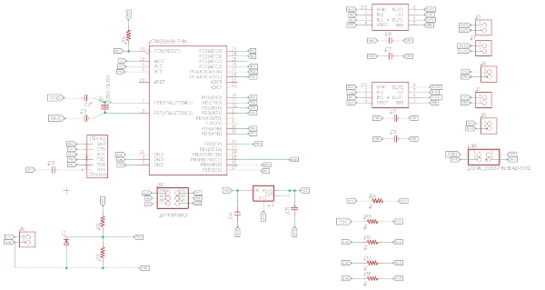
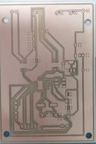
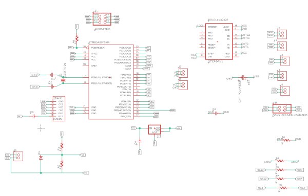
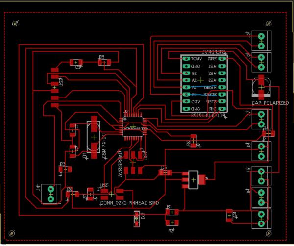
I made the board design on Eagle and the picture of the board and schematic can be shown below. I will also put my Eagle files and the bottom of the page.
I used FlatCam to create all the files that are necessary for the board. The type of files that are available in the program are Gerber which is used for outlines and traces of the border and Excellon which is used for the drill.
To make the board design I inputted the following settings in the programs I got from maha
-
Tool diameter: 0.4 mm
-
Number of passes: 4
-
Passes Overlap: 60%
And after I inputted everything I check on the combine check box.
To make the CNC object files I have to input the following settings:
-
Cut Z: -0.1
-
End Move Z: 60
-
Feedrate X-Y: 240
-
Feedrate Z: 80
To make the Isolation Geometry I inputted these settings:
-
Tool Diameter: 0.8 mm
-
Number of Passes: 1
-
Passes Overlap: 60%
And after inputting everything I have to check the combine and external isolation checkboxes.
To make the CNC object file I inputted these settings:
-
Cut Z: -1.7mm
-
Check Multi-Depth Value: 0.7
-
End Move Z: 60
-
Feedrate X-Y: 240
-
Feedrate Z: 80
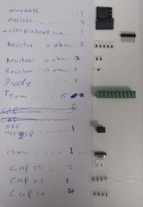
Electronics
For the electronics section of the project I have used these components that are listed in the picture below.
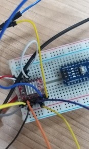
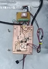
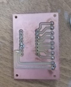
I inputted the settings in the machine and it started making the board.
The board is made and ready to add the components on it.
I used the solder to fix the components of the board onto it.
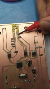
I added the chips.
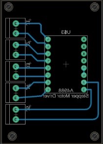
This picture shows a description of the stepper motor driver board and the motor sensor and how it works.
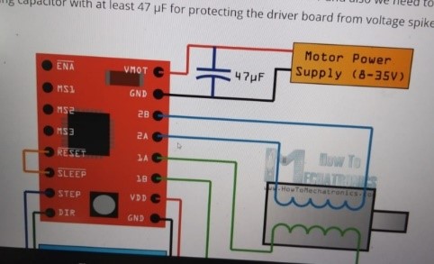
This picture shows a sketch of the connections and the power of the stepper motor driver board and the power source.
A4988 Driver
-
Plan A: Motor driver A49535
-
12 V Output
-
Input 12 V
-
12V battery voltage meter with resistor 5k and resistor 10k and I got the information from the video
- LED output
The motor driver I tried designing didn’t not work, so I used a ready-made motor driver for the motor I am using in the case
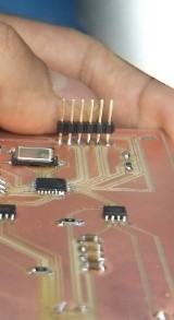
The connection
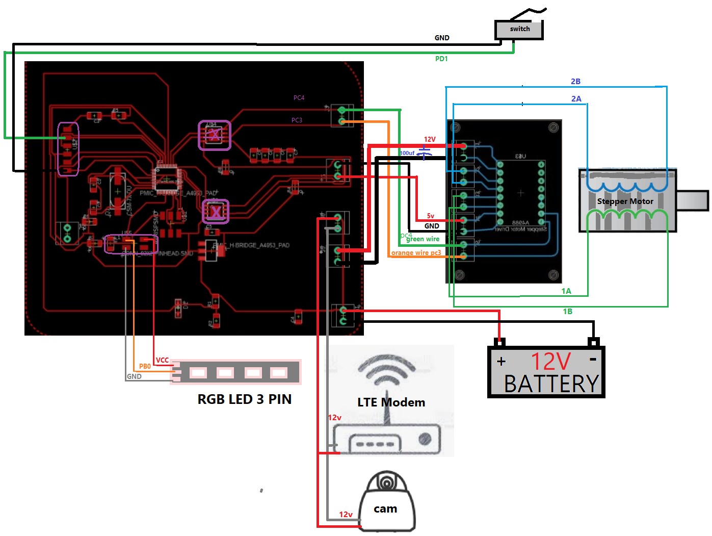
Inputs and Outputs Pins to Atemga328p board:
-
RGB LED: is connected to pin PB0 in Atemga328p board.
-
LTE Modem and CAM: is connected directly to the power pins of the ATemga 328p board.
-
Switch is connected to pin PD1 in Atemga328p board.
-
Stepper motor: is connected to the motor drive board.
| Motor drive A4988 board pins | Stepper motor pins |
|---|---|
| MS3 | 2B |
| MS2 | 2A |
| MS1 | 1A |
| ENABLE | 1B |
- Motor drive A4988:
| Motor drive A4988 board pins | Atemga 328p board pins |
|---|---|
| DIR | PC4 |
| STEP | PC3 |
Note:
-
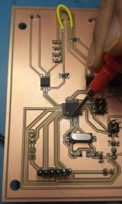
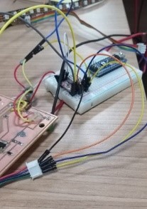
I tested the operation of the motor driver and the stepper motor back on the output devices, using an arduino due to the pandamic.
-
I have not used the embedded motor drivers on the board (as displayed on the image, I have connected the pins directly) due the overload on the embedded motor drivers. As the motor could not run, but instead make a ticking sound indicating an overload. I have thus used an external motor driver to connect to my stepper motor.
Programming
I used the following code to test the RGB LED strip I used for my final project. I set the output pin of the LED strip and tested it to display the colors green and red using Arduino IDE.
/ NeoPixel test program showing use of the WHITE channel for RGBW
// pixels only (won’t look correct on regular RGB NeoPixel strips).
#include <Adafruit_NeoPixel.h>
#ifdef __AVR__
 #include <avr/power.h> // Required for 16 MHz Adafruit Trinket
#endif
#define LED_PIN     6 // Which pin on the Arduino is connected to the NeoPixels?
#define LED_COUNT  10 // How many NeoPixels are attached to the Arduino?
#define BRIGHTNESS 50 // NeoPixel brightness, 0 (min) to 255 (max)
Adafruit_NeoPixel strip(LED_COUNT, LED_PIN, NEO_GRBW + NEO_KHZ800);
void setup() {
  clock_prescale_set(clock_div_1);
  strip.begin();           // INITIALIZE NeoPixel strip object (REQUIRED)
  strip.show();            // Turn OFF all pixels ASAP
  strip.setBrightness(50); // Set BRIGHTNESS to about 1/5 (max = 255)
}
void loop() {
  // Fill along the length of the strip in various colors...
     colorWipe(strip.Color(255,   0,   0)     , 50); // Red
    delay(2000);
    colorWipe(strip.Color(  0, 255,   0)     , 50); // Green
    delay(2000);
}
void colorWipe(uint32_t color, int wait) {
  for(int i=0; i<strip.numPixels(); i++) { // For each pixel in strip...
    strip.setPixelColor(i, color);         //  Set pixel’s color (in RAM)
    strip.show();                          //  Update strip to match
    delay(wait);                           //  Pause for a moment
  }
}
    strip.show(); // Update strip with new contents
    // There’s no delay here, it just runs full-tilt until the timer and
    // counter combination below runs out.
    firstPixelHue += 40; // Advance just a little along the color wheel
    if((millis() - lastTime) > whiteSpeed) { // Time to update head/tail?
      if(++head >= strip.numPixels()) {      // Advance head, wrap around
        head = 0;
        if(++loopNum >= loops) return;
      }
      if(++tail >= strip.numPixels()) {      // Advance tail, wrap around
        tail = 0;
      }
      lastTime = millis();                   // Save time of last movement
    }
  }
}
I used the following code from stoper motor code to test the motor driver and stepper motor.
/*Example sketch to control a stepper motor with A4988 stepper motor driver and Arduino without a library. More info: https://www.makerguides.com */

// Define stepper motor connections and steps per revolution:
#define dirPin 3
#define stepPin 4
#define stepsPerRevolution 200

void setup() {
  // Declare pins as output:
  pinMode(stepPin, OUTPUT);
  pinMode(dirPin, OUTPUT);
}

void loop() {
  // Set the spinning direction clockwise:
  digitalWrite(dirPin, HIGH);

  // Spin the stepper motor 1 revolution slowly:
  for (int i = 0; i < stepsPerRevolution; i++) {
    // These four lines result in 1 step:
    digitalWrite(stepPin, HIGH);
    delayMicroseconds(2000);
    digitalWrite(stepPin, LOW);
    delayMicroseconds(2000);
  }

  delay(1000);

  // Set the spinning direction counterclockwise:
  digitalWrite(dirPin, LOW);

  // Spin the stepper motor 1 revolution quickly:
  for (int i = 0; i < stepsPerRevolution; i++) {
    // These four lines result in 1 step:
    digitalWrite(stepPin, HIGH);
    delayMicroseconds(1000);
    digitalWrite(stepPin, LOW);
    delayMicroseconds(1000);
  }

  delay(1000);

  // Set the spinning direction clockwise:
  digitalWrite(dirPin, HIGH);

  // Spin the stepper motor 5 revolutions fast:
  for (int i = 0; i < 5 * stepsPerRevolution; i++) {
    // These four lines result in 1 step:
    digitalWrite(stepPin, HIGH);
    delayMicroseconds(500);
    digitalWrite(stepPin, LOW);
    delayMicroseconds(500);
  }

  delay(1000);

  // Set the spinning direction counterclockwise:
  digitalWrite(dirPin, LOW);

  //Spin the stepper motor 5 revolutions fast:
  for (int i = 0; i < 5 * stepsPerRevolution; i++) {
    // These four lines result in 1 step:
    digitalWrite(stepPin, HIGH);
    delayMicroseconds(500);
    digitalWrite(stepPin, LOW);
    delayMicroseconds(500);
  }

  delay(1000);
}
New board:
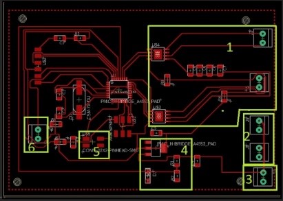
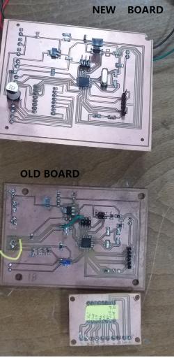
I mill new board because the FTDI was not working, I think the reason why the FTDI not worked, was because the traces was damaged. as shown in Interface and application programming assignment I use the FTDI header and worked very well. This exactly the same compounts previous one but one of the changes I have in my new board, I did a built-in motor drive instead of having a separated board of the motor drive.
Schematic:
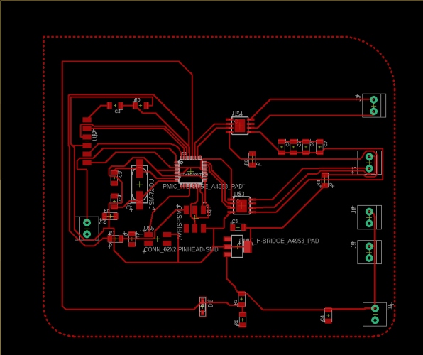
Layout:
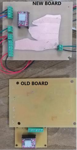
NEW BOARD AND OLD BOARD
Adjust A4988 stepper motor driver
their was problem with A4988 motor drive, whenever i press the heat sink or the RST pin in the Driver, the stepper motor was working and noise sound come from the motor. To fix the problem I connect the RST pin with SLP pin in the motor drive i add solder to connect the pins. The schematic of A 4988 motor drive:

This video display the problem and how i fix it, how in the end the stepper motor work:
3D designing and Printing
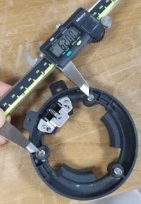
I took the measurements of the camera by measuring the screw hole and diameter of the camera holder and then I design the piece.
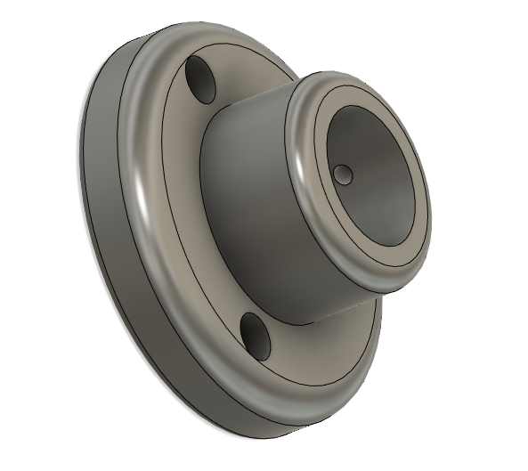
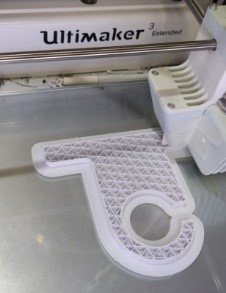
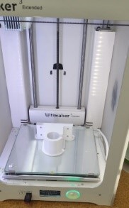
and then printed the piece.
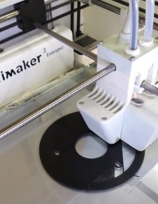
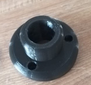
I design the camera holder and printing the camera holder using the 3D printer.
I inputted the measurements of the camera safety holder and the result is shown above.
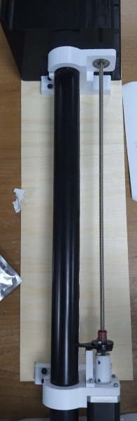
I inputted the measurements of the camera tube holder and the results are shown above.
After I finished printing the parts I tried the camera holder by placing a wooden board between the camera holders to see if they fit in properly.
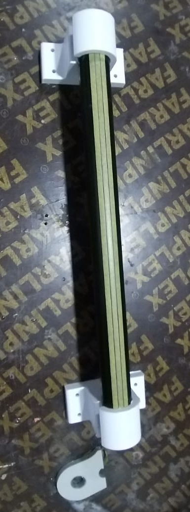
I assembled the pieces that I made onto each other. The camera tube onto the camera holder connected to the camera case.
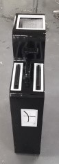
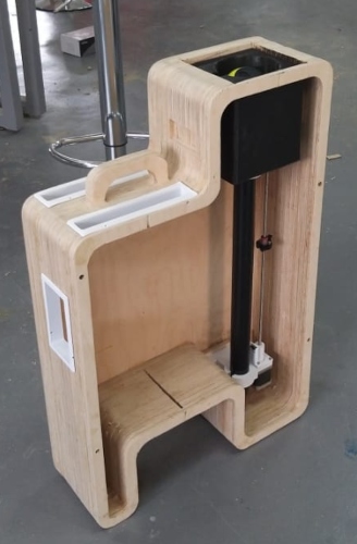
After making sure that the pieces are connected properly I tried assmeblying them in the Plywood case and tried to fit them in neatly.
challenges:
The programming part was a challenge to me, and I faced difficulties in it as I didn’t have much experience. Producing the board was a bit hard, because the board kept having faults in it. Creating the case was not very hard, but putting it together took some physical effort.
Future development:
For the future I would like the case to have another heat sensing camera to detect the different temperatures ranges from different parts of the room. I also want to add another camera for zooming in, and having a better view of the place.
Files
final project cases fusion 360 file
final project eagle File brd new
final project eagle File sch new

This work is licensed under a Creative Commons Attribution 4.0 International License.