10. Molding and Casting
The Assignment
To design a 3D mold, machine it and use it to cast parts.
Designing the Mold
For this assignment I am asked to design a mold and to use it. At first I had trouble trying to think of a design to make, so I decided to choose drone arm as a mold to make for this assignment.
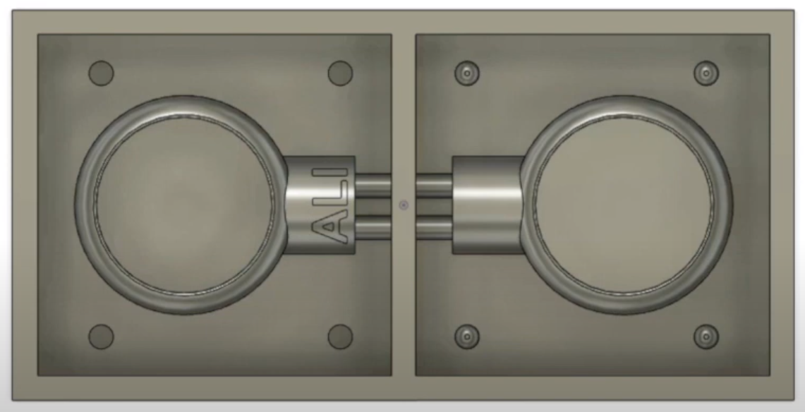
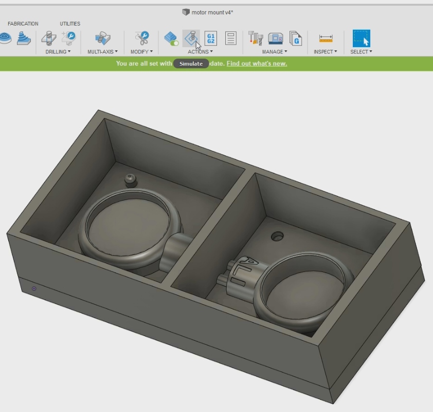
This is the mold desing that I made using Fusion 360 and I will show the steps I made while making it in the video below.
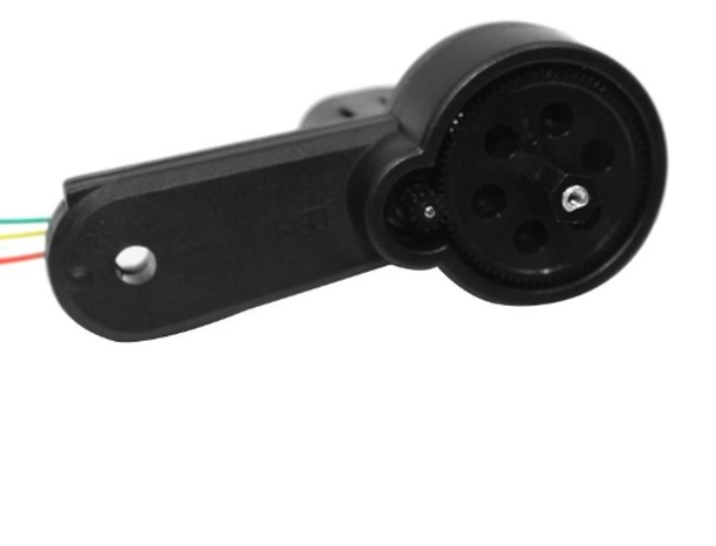
I decided to choose that idea since I use drones and sometimes my drone parts break off so I want to learn how to make parts by myself using molds. This drone arm model is different than the ones I use but I wanted to test making a mold.
I used Fusion 360 and started taking my measurements of the brushless motor and the steps are shown in the video below.
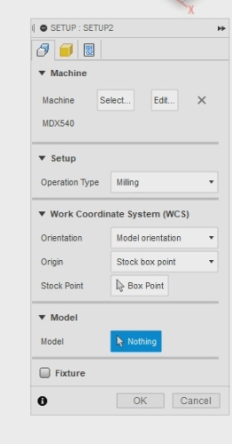
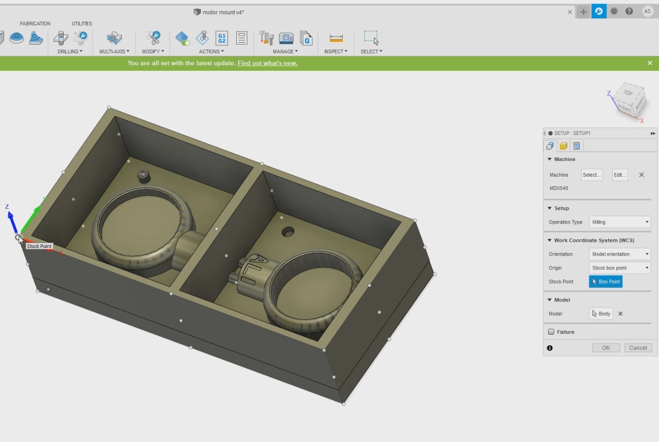
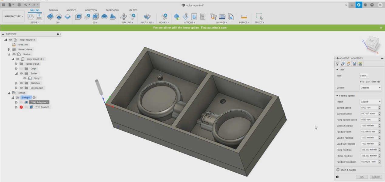
I opened Fusion 360 and clicked on “Setup” then “New Setup” which is under the “Milling” section.

After clicking on setup I clicked on “Model” and clicked on “Nothing” to select the body of my mold.
Here in this picture I clicked on the body to select it and after it I clicked on the Origin to pick on the starting point of the mold.

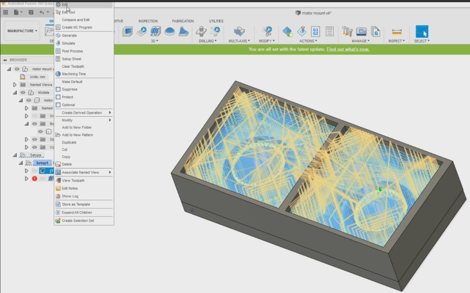
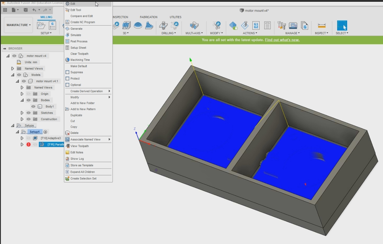
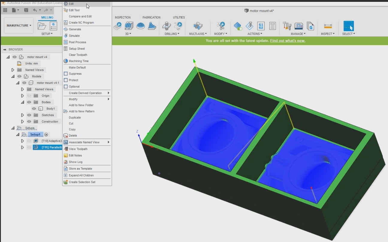
I right clicked the “Setup1” file and clicked on Edit.
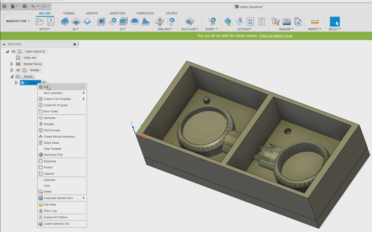
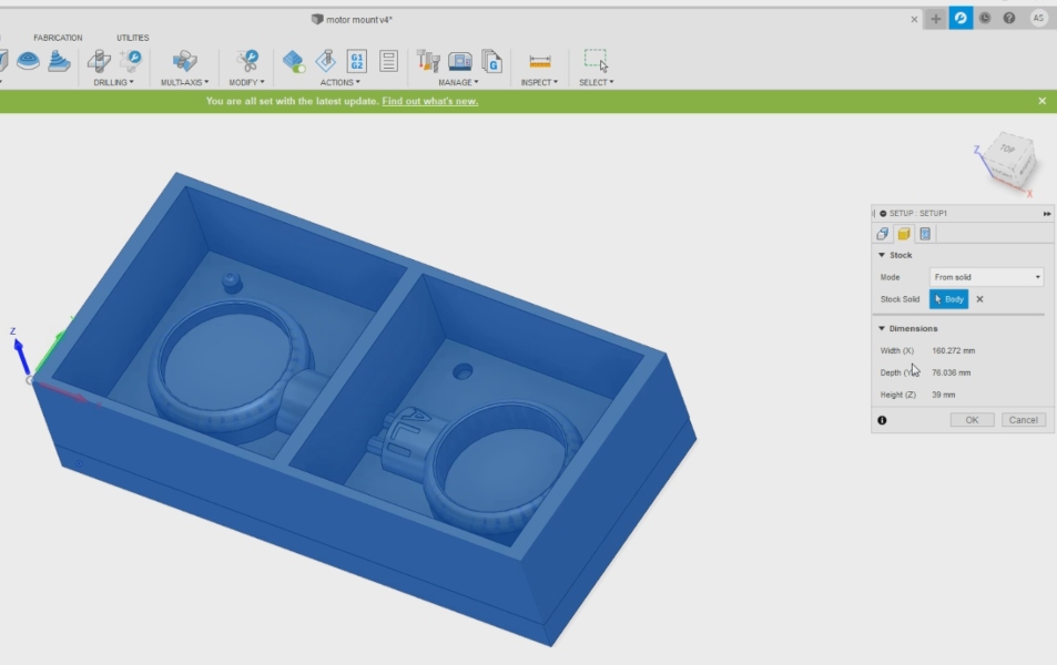
I made sure that the mold body is selected so I can start my process.
I clicked on “Stock” and made sure that I clicked on “Body” at the “Stock Solid”.
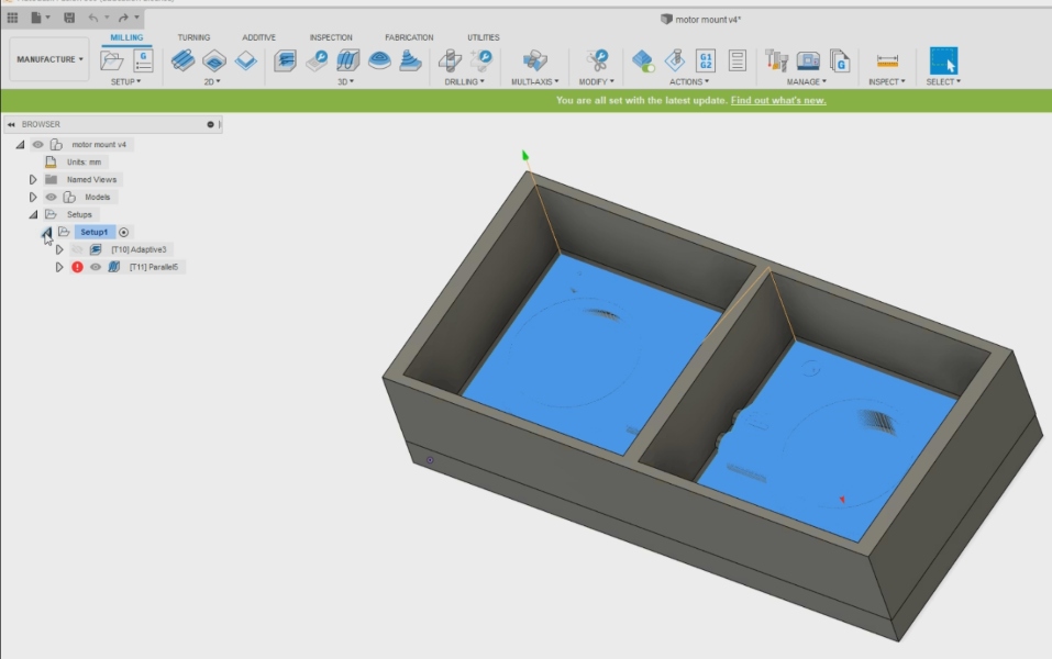
Here under the “Setup1” file I made 2 files named “Adaptive” and “Parallel” which I will use to mill my mold.
Now I right clicked on “Adaptive” and clicked on “Edit”
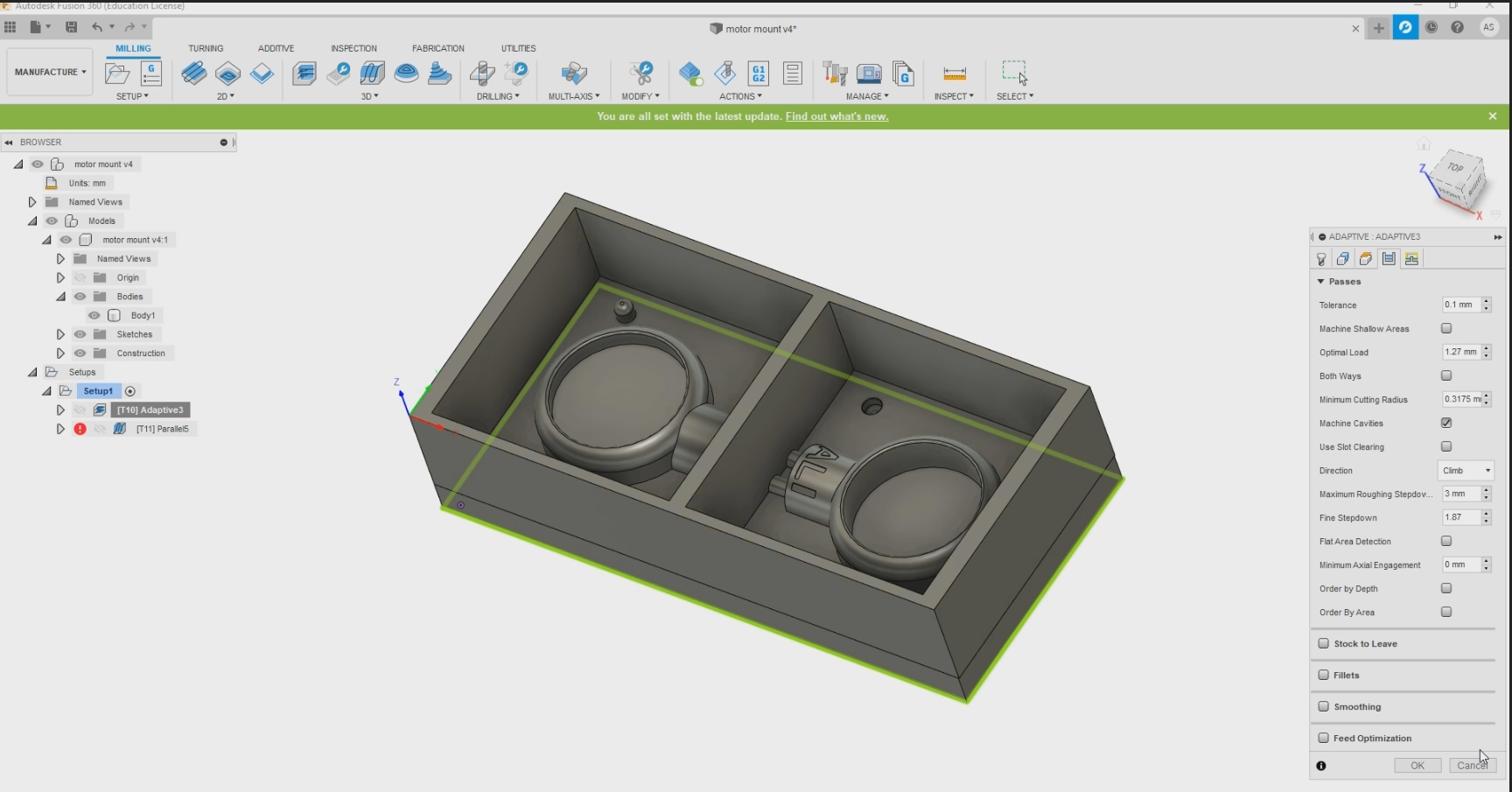
Now that I inputted the settings I wanted onto the small window on the right.
My settings can be shown here in the picture below.
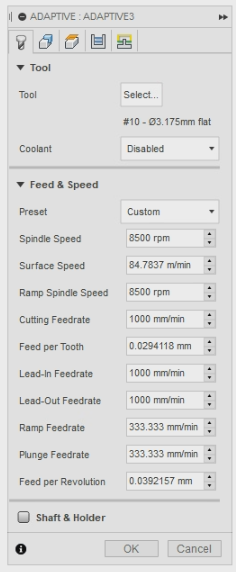
I now have to select the tool that I want to use so I picked the tool shown below in the picture. This tool is used to remove all the part that we do not need in the fastest way.
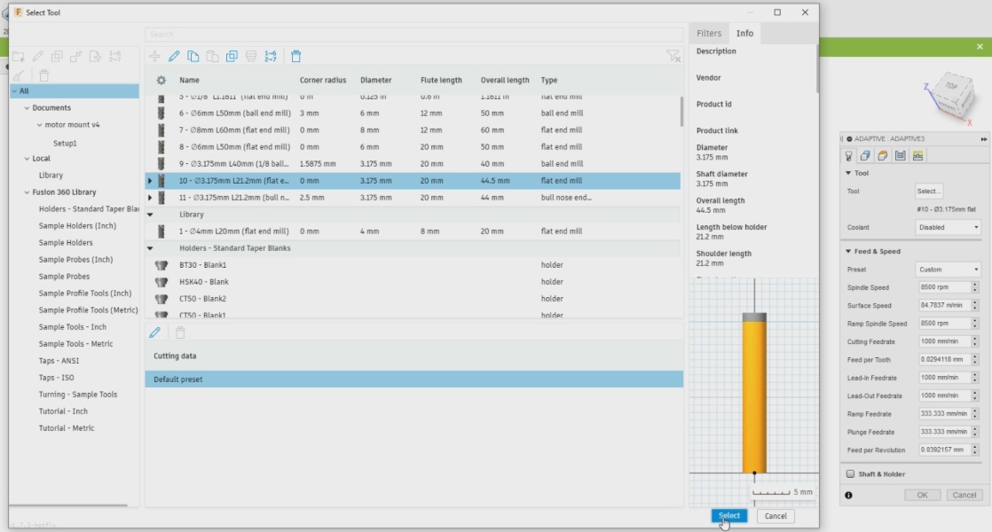
This is the tool I used for the milling in the “Adaptive”

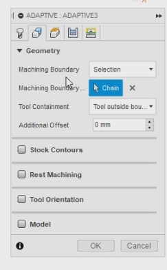
I also entered the other settings for he “Geometry” section.
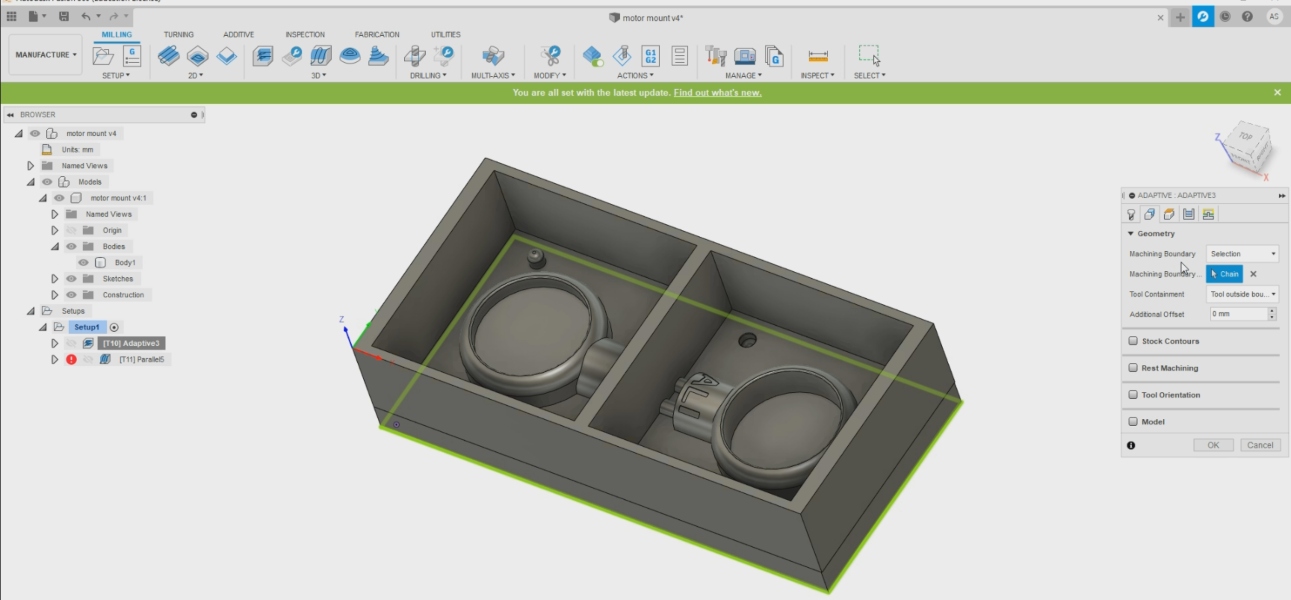
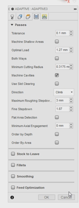
Here I fixed the settings for the “Passes” section.
My settings for the “Passes” section are shown below.
I right clicked the “Parallel” and clicked on “Edit”.
I chose the drill that I wanted to use for milling the “Parallel” section of the mold.
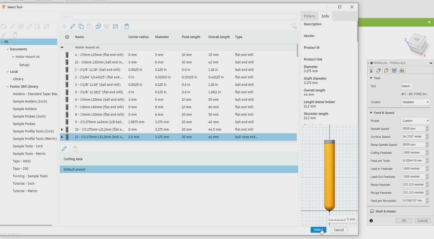
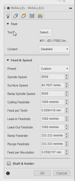
After choosing the milling tool I entered the settings in the window on the right.
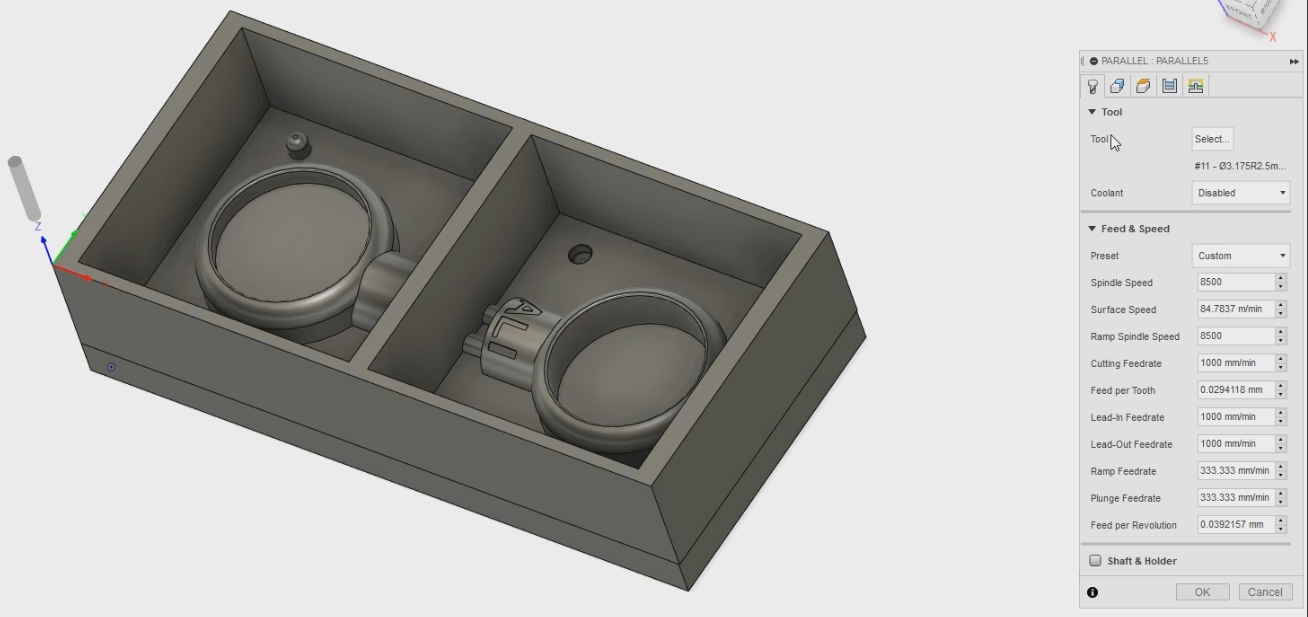
The settings of the “Parallel Tool” is shown below.
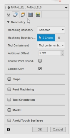
Now I opened the “Geometry” section and started inputting the settings
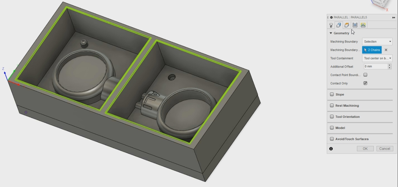
These are the settings of the “Geometry” section.
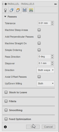
Now I will add the settings for the “Passes” section.
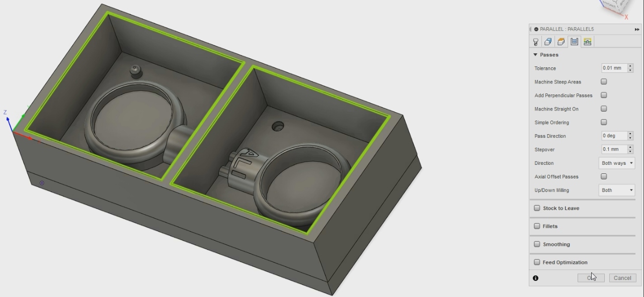
These are the settings for the “Passes” section.
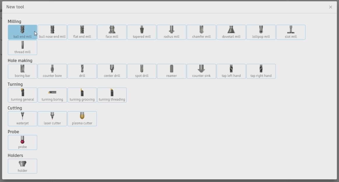
Now I clicked on “New Tool” to create a new tool to use.

Then I clicked on “Ball End Mill” under the Milling sections.
Now I entered the required settings for the tool as shown before.
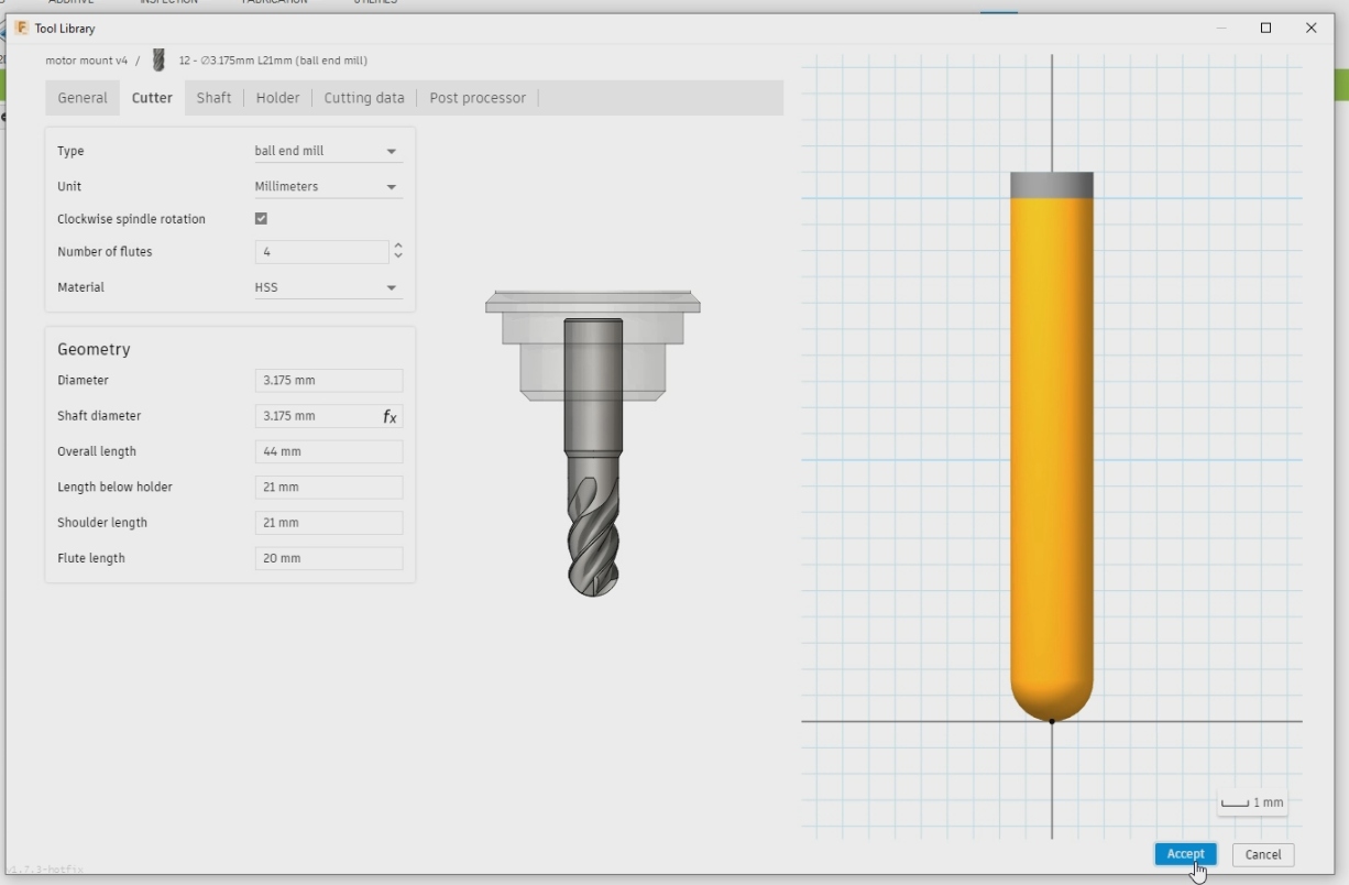
Now I finished creating the new tool and I click on it. This milling tool is used to make details on the mold and for final finishings.
Now I right clicked on the “Parallel” and then edit.
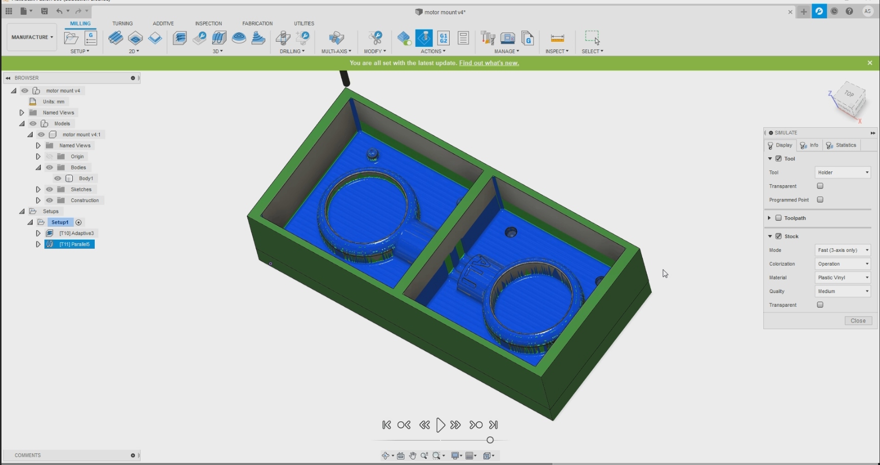
Now since I inputted the settings I can make sure that the two milling options will mill properly. The first one is “Adaptive” that will mill at -17.5 mm and then the “Parallel”

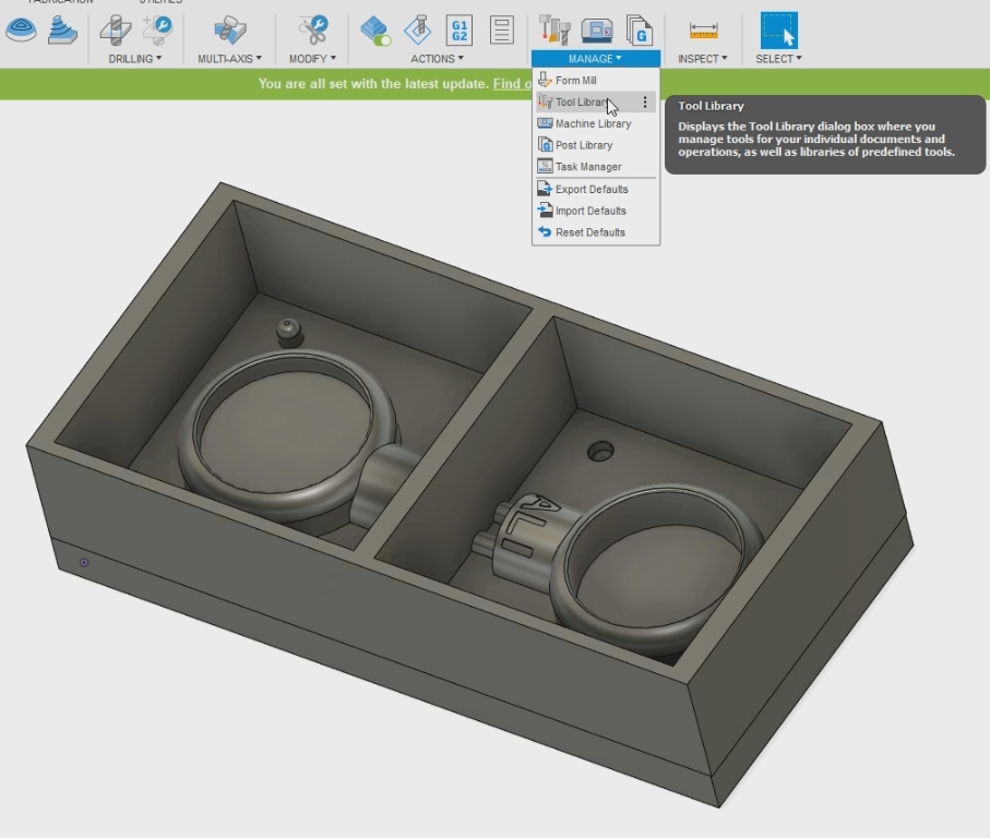
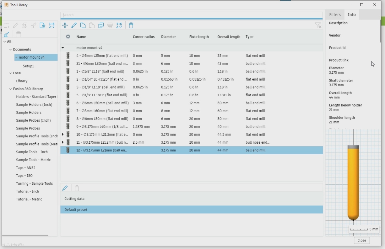
Now I choose the “Manage” and then “Tool Library”.
Now to check the milling movement we need to click on “Simulate” under the “Actions” tab.
Now I can start using the Simulator to preview the milling movements.
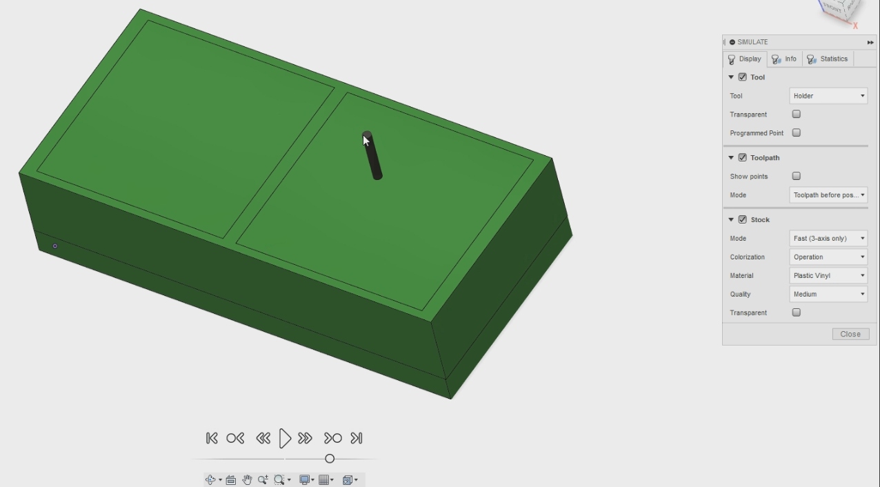
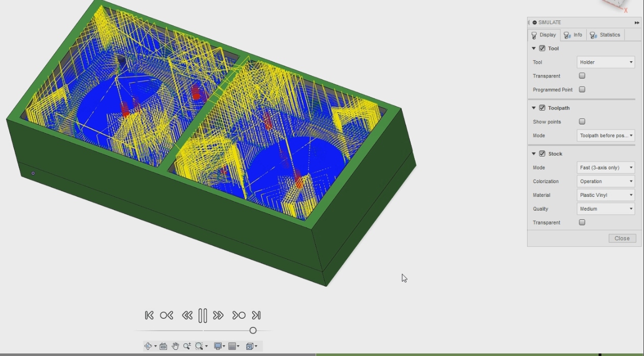
The video shows how the tools will start milling the mold in 2 parts one with the “Adaptive” file and the second with the “Parallel” file.
Now you can see how the finished product will be after the milling settings have been made.
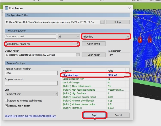
Now we need to prepare the file so that we can import into the machine. First step is to right click on “Adaptive” and then click on “Post Process”. This small window will appear and now we have to input the settings we want to match the machine that we will use. I clicked on “All vendors” and chose “Roland DG” and then I clicked on “value” and chose “MDX-40” and the red boxes below show where I made my changes at. After it I clicked on “Post” and saved the file on my Desktop and repeated the same process from “Parallel”.
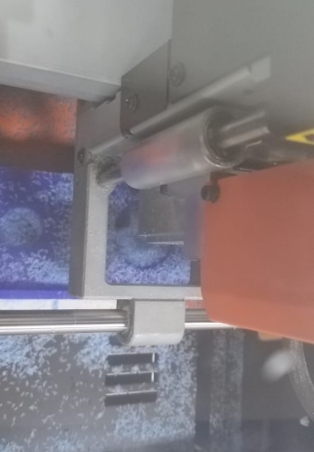
To start milling I had to move the prepared files onto a flash memory and input it into the machine’s software, inserted the correct milling tool, and gave the command to start milling.
In this picture the machine “Roland MDX 40” is milling the piece.
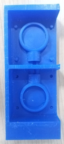
This is the final product of the mold.
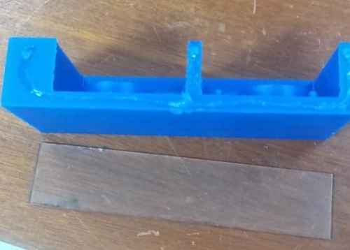
Now I have to add the acrylic piece on the side of the mold because the mold piece wasn’t enough so I added the acrylic to continue my next step.
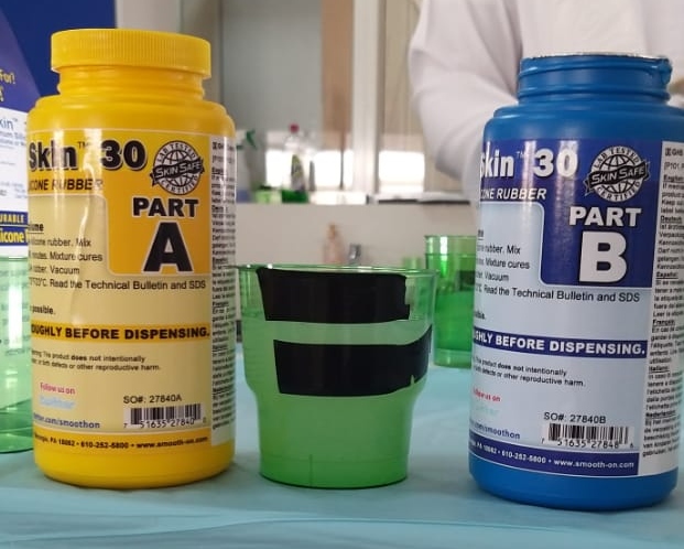
Safety Procedures for Dragon Skin 30
To start working on the mold I have to follow these safety procedures shown in the picture below.
I got these safety instructions from Hashim and the link in shown here.
Making the Silicone Dragon Skin 30 Mold
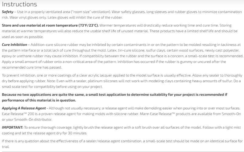
I started by filling the mold with water to know how much liquid can be filled in the mold.
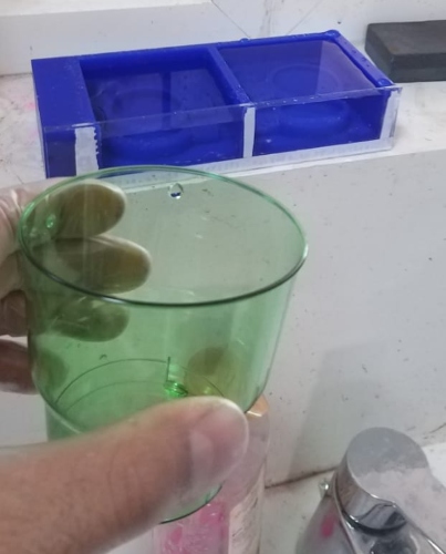
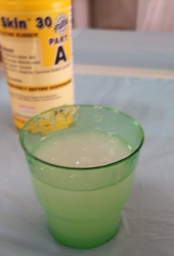
Now since I know the amount of liquid required I divided the amount into two Plastic cups and I marked the amount by placing a sticker of the cups.

I weighted the half of the quantity of the water and it showed 87.5 grams.
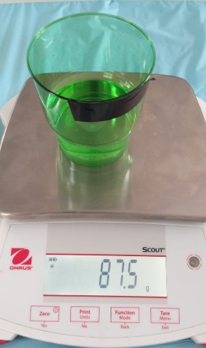
Now since the water weighs 87.5 I know have to multiply it by 2 to know the other quantities required for the silicone.
I filled the Part A silicone until the start of the first black tape and then I continued by pouring the Part B of silicone in the same cup until it reached the start of the second black tape. The ratio of the silicone mixture is 1:1 of each part.
Now I have to mix the liquid with a wooden stick for two minutes and I mixed while using a timer. Then I put the mixture into another cup and then I mixed it again for two minutes using a timer.
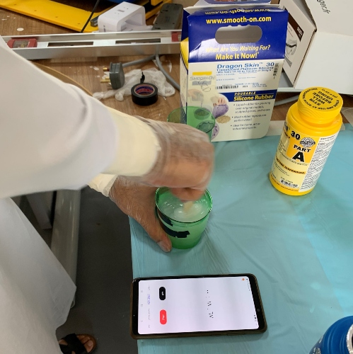
Now the silicone mixture is ready to be used for my mold.
I poured the silicone mixture into the mold and now I have to leave it for 24 hours to be sure it hardens so I can remove it after that.
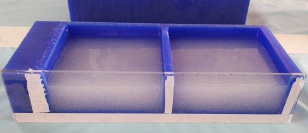
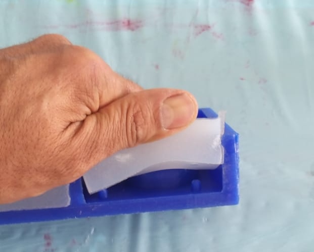
After 24 hours I removed the acrylic piece from the mold so it will be easier for me to peel the silicone from the mold.
Now I am starting little by little peeling the silicone from the mold.
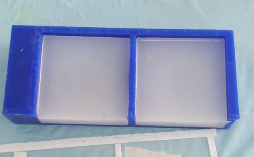
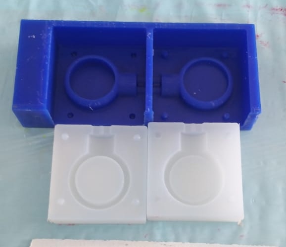
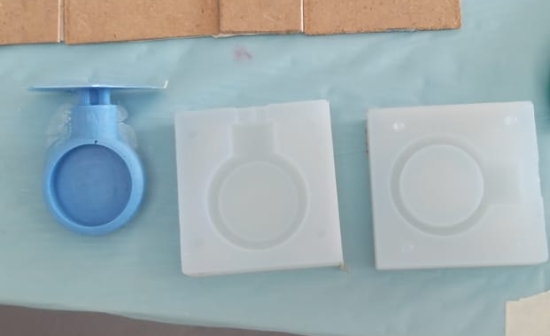
This picture shows the 2 pieces removed from mold.
Safety Procedures for Task 4 Resin
To start working on the resin I have to follow these safety procedures shown in the picture below.
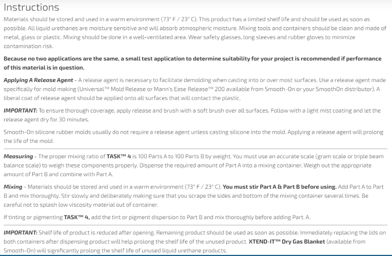
I got these safety instructions from Hashim and the link in shown here.
Making the Motor Mount Part (Task 4 Resin)
Now I am measuring the amount of water I can put in the mold so I can later add the resin. The amount of water I can put in the mold is 30 ml.

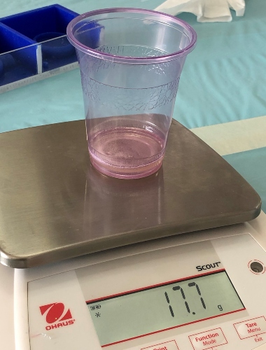
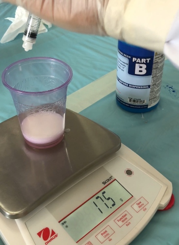
Since I need to put 15 ml of epoxy in the mold for one part of the resin. I need to take the amount 3 times for one part since my syringe is 5ml and the total of one part of resin is 15 ml and in weight is 17.7 grams. The total for both parts of resin which are Part A and Part B is 35.4 grams. The ratio of the resin mixture is 1:1 of each part.
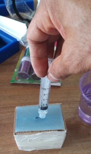
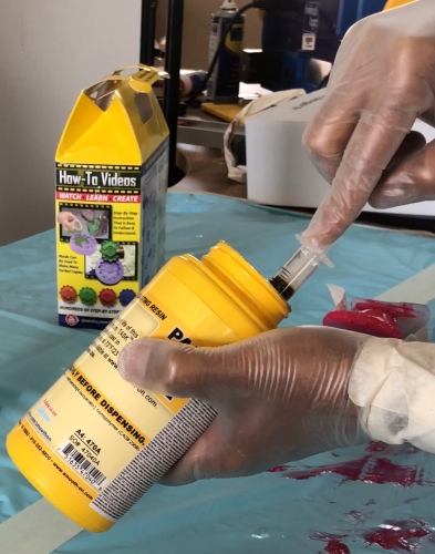
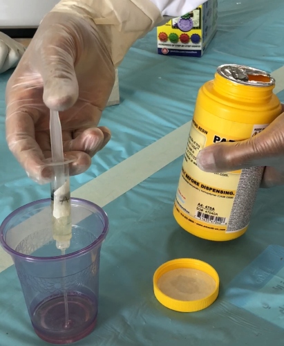
Now I am measuring the Resin Part A using a syringe. My syringe is 5 ml and I need to add 15 ml of Part A so I took 5 ml using the syringe 3 times to get the amount I want.
The weighted the resin using the balance scale by resetting the balance once I placed the previous amount of resin and now the amount for Part B is 17.7 grams.
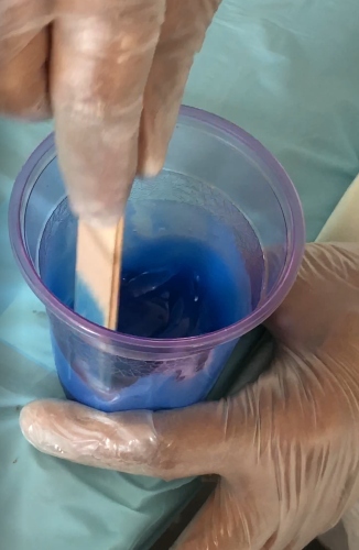
Now I mixed the two parts of resin together for 30 seconds and colored it the color blue. Then I put the mixture in another cup and mixed it for 30 seconds again using a timer.
Now I am putting the combined resin into the mounting motor mold.
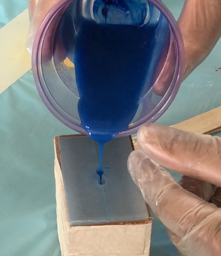
After we mixed the resin we added it in the mold.
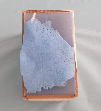
After 24 hours the material hardened and can be removed from the mold.
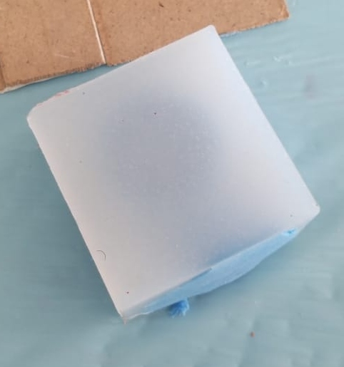
Here I removed the mold and you can see the motor mount.
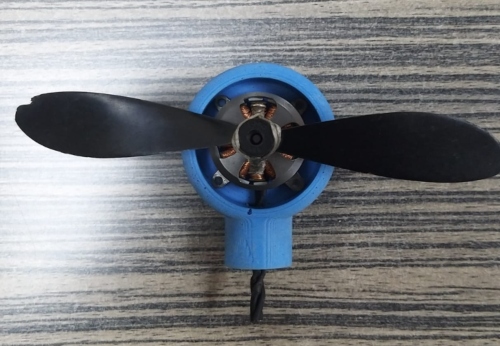
Final Product
Now the motor mount is ready to be used as a part of the drone. The part is little heavy but is nice and very strong.
Group Assignment: Molding and casting link.

This work is licensed under a Creative Commons Attribution 4.0 International License.