12. Output devices
Arduino Brushless Motor Control | ESC |
Group Assignment
Measure the power consumption of an output device.
Individual Assignment
Add an output device to a microcontroller board you’ve designed, and program it to do something
Introduction:
For this week I will be making two assignments using an Arduino board. Beacuse of the panemdemic I am using Arduino since I cannot get another board. My two assignmets being first a brushless motor and the second will be a stepper motor.
Brushless Motor
The components I used are:
1- Arduino Uno
2-RC ESC 3cell
3- Brash Motor KV1700
4- 3S LiPo Battery
5-10k Poten-Tiometer
6-wire
7- Breadboard
I connected all my materials together as shown in the pic .
(ESC Signal)
ESC wire yellow to D9
ESC wire black to GND
ESC wire red to 5V
(ESC Power )
ESC Power In 11.1 V
(10K Poten Tiometer)
Poten Tiometer wire yellow to analog A0
Poten Tiometer wire black to GND
Poten Tiometer wire red to 5V
(3S Lipo Battery 11.1v )
3S Lipo Battery 11.1v to ESC Motor
(Brushless MOTOR )
Brushless MOTOR TO ESC
Operating the Brushless Motor
To start making my Brushless motor I have to start assembling the components that I have with me. All of the components that I used are shown in the list above. I used a 3S Lipo Battery which has 3 cells and that is 11.1 V and that is enough to keep my brushless motor running perfectly. Since the brushless motor is very power hungry we used this 11.1 V battery to give it enough power it needs to work.
The cell battery has 3 wires which forms what is called a Battery Eliminator Circuit that I will explain each one of it’s wires and their function. The yellow wire is used for the signal from the board. The red wire is used for the VCC +5V, and the black wire is used for the ground.
The Potentionmeter is used to control the power of the motor by increasing and decreasing the RPM of the brushless motor. I learned about these steps from this link.
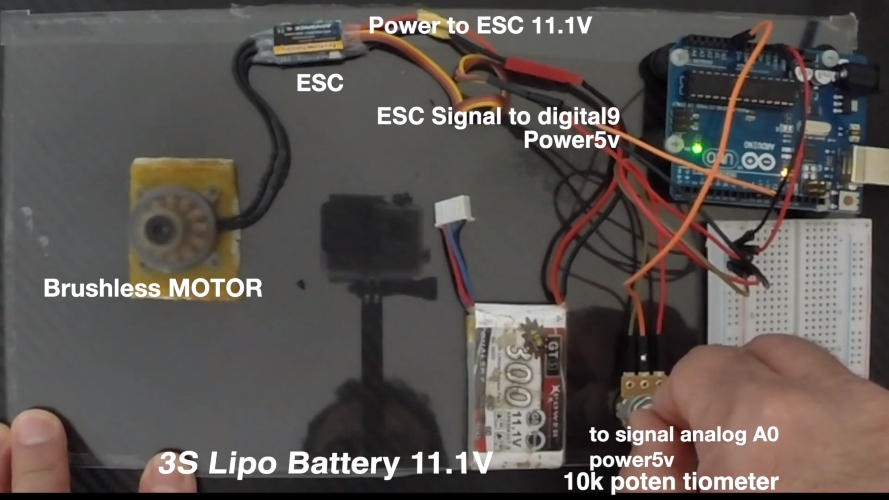
This picture shows the final assembled circuit I used for this assignment.
Code
/*

*/
#include <Servo.h>
Servo ESC;     // create servo object to control the ESC
int potValue;  // value from the analog pin
void setup() {
  // Attach the ESC on pin 9
  ESC.attach(9,1000,2000); // (pin, min pulse width, max pulse width in microseconds)
}
void loop() {
  potValue = analogRead(A0);   // reads the value of the potentiometer (value between 0 and 1023)
  potValue = map(potValue, 0, 1023, 0, 180);   // scale it to use it with the servo library (value between 0 and 180)
  ESC.write(potValue);    // Send the signal to the ESC
}
Stepper Motor
For the Stepper motor I will be listing all the components that I have used to make it below and I learned how to make this project from this website:
Arduino Board
Jumper
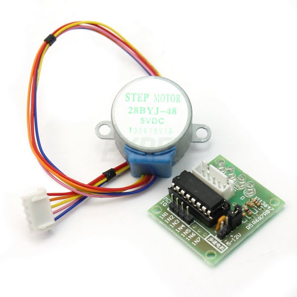
BYJ48 Stepper Motor 5v
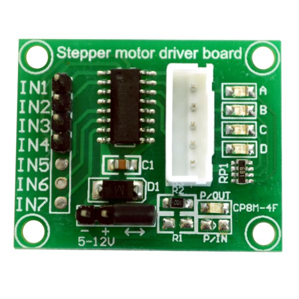
Stepper Motor Driver Board ULN2003
For the stepper motor I will also be using Arduino board to send signals to control the stepper motor. The stepper motor is used as an output to show the results of the code as the motor rotates clockwise and counter clockwise. Stepper Motor Driver Board is used to give commands from the Arduino board to the stepper motor. This is the drawing sketch of how I aligned my stepper motor and it’s components.
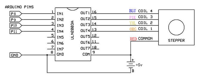
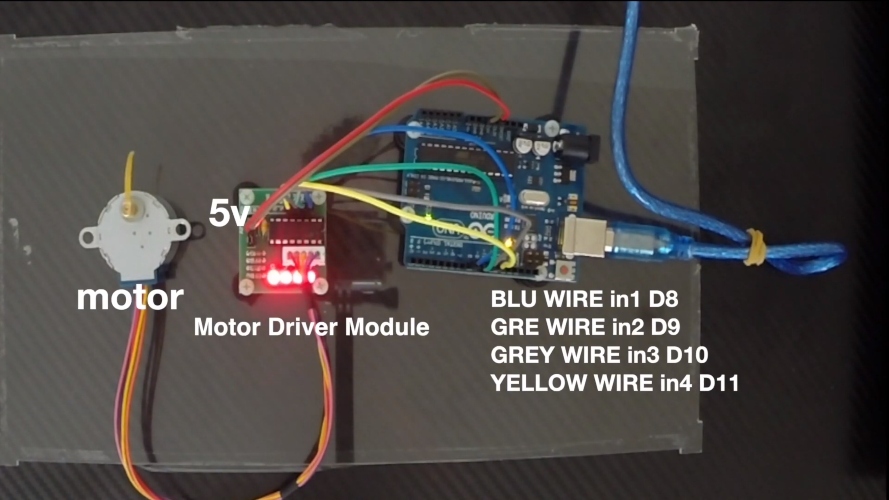
Now the picture below shows the Stepper board all connected to each other and the video below shows the motor working properly and how I operate it. The connections I made from the Motor Driver Board to the Arduino board are as follows:
I connected the Motor Driver Board Blue wire from in1 to D8 in Arduino Board.
I connected the Motor Driver Board Green wire from in2 to D9 in Arduino Board.
I connected the Motor Driver Board Grey wire from in3 to D10 in Arduino Board.
I connected the Motor Driver Board Yellow wire from in4 to D11 in Arduino Board.
Code for Stepper Motor
/*
   BYJ48 Stepper motor code
   Connect :
   IN1 >> D8
   IN2 >> D9
   IN3 >> D10
   IN4 >> D11
   VCC ... 5V Prefer to use external 5V Source
   Gnd
   written By :Mohannad Rawashdeh
https://www.instructables.com/member/Mohannad+Rawashdeh/
     28/9/2013
  */

#define IN1  8
#define IN2  9
#define IN3  10
#define IN4  11
int Steps = 0;
boolean Direction = true;// gre
unsigned long last_time;
unsigned long currentMillis ;
int steps_left=4095;
long time;
void setup()
{
Serial.begin(115200);
pinMode(IN1, OUTPUT);
pinMode(IN2, OUTPUT);
pinMode(IN3, OUTPUT);
pinMode(IN4, OUTPUT);
// delay(1000);

}
void loop()
{
  while(steps_left>0){
  currentMillis = micros();
  if(currentMillis-last_time>=1000){
  stepper(1);
  time=time+micros()-last_time;
  last_time=micros();
  steps_left--;
  }
  }
   Serial.println(time);
  Serial.println("Wait...!");
  delay(2000);
  Direction=!Direction;
  steps_left=4095;
}

void stepper(int xw){
  for (int x=0;x<xw;x++){
switch(Steps){
   case 0:
     digitalWrite(IN1, LOW);
     digitalWrite(IN2, LOW);
     digitalWrite(IN3, LOW);
     digitalWrite(IN4, HIGH);
   break;
   case 1:
     digitalWrite(IN1, LOW);
     digitalWrite(IN2, LOW);
     digitalWrite(IN3, HIGH);
     digitalWrite(IN4, HIGH);
   break;
   case 2:
     digitalWrite(IN1, LOW);
     digitalWrite(IN2, LOW);
     digitalWrite(IN3, HIGH);
     digitalWrite(IN4, LOW);
   break;
   case 3:
     digitalWrite(IN1, LOW);
     digitalWrite(IN2, HIGH);
     digitalWrite(IN3, HIGH);
     digitalWrite(IN4, LOW);
   break;
   case 4:
     digitalWrite(IN1, LOW);
     digitalWrite(IN2, HIGH);
     digitalWrite(IN3, LOW);
     digitalWrite(IN4, LOW);
   break;
   case 5:
     digitalWrite(IN1, HIGH);
     digitalWrite(IN2, HIGH);
     digitalWrite(IN3, LOW);
     digitalWrite(IN4, LOW);
   break;
     case 6:
     digitalWrite(IN1, HIGH);
     digitalWrite(IN2, LOW);
     digitalWrite(IN3, LOW);
     digitalWrite(IN4, LOW);
   break;
   case 7:
     digitalWrite(IN1, HIGH);
     digitalWrite(IN2, LOW);
     digitalWrite(IN3, LOW);
     digitalWrite(IN4, HIGH);
   break;
   default:
     digitalWrite(IN1, LOW);
     digitalWrite(IN2, LOW);
     digitalWrite(IN3, LOW);
     digitalWrite(IN4, LOW);
   break;
}
SetDirection();
}
}
void SetDirection(){
if(Direction==1){ Steps++;}
if(Direction==0){ Steps--; }
if(Steps>7){Steps=0;}
if(Steps<0){Steps=7; }
}
I used a stepper motor for my final project here in this link.
This video shows the two projects and how they can operate using the boards.

This work is licensed under a Creative Commons Attribution 4.0 International License.