7. Electronics design
Group Assignment
Use the test equipment in your lab to observe the operation of a microcontroller circuit board.
Document your work (in a group or individually)
My part in the group project was to see the difference between Conventional milling and Climbing milling.
Individual Assignment
Redraw an echo hello-world board.
Add (at least) a button and LED (with current-limiting resistor).
Check the design rules, make it, and test it.
Extra credit: simulate its operation.
Introduction
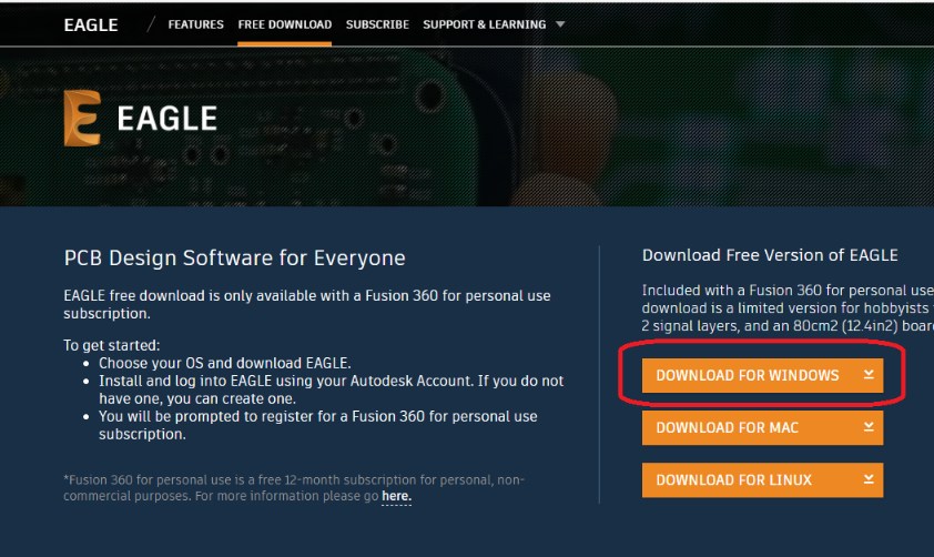
For this assignment I have to work on two programs that were told to us by Fab Lab for us to work on. The first program is called Eagle and I have to download this software from their official site that was given to us by Hashim during our lecture.
The link is shown here.
I have downloaded the Eagle app for Windows.
I used the fab academy reference. to create the Atiny44 circuit board.
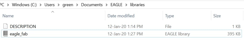
To start using the fab library, I had to s copy the file into the eagle lib directory.
I designed this circuit board using the Atiny44 model that was given to us.
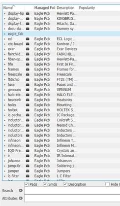
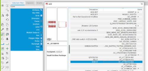
To start adding the components to my schematic, I clicked on the add part icon on the left tool bar, then I navigated to the eagle fab library and choose the component I needed ( for example ATtiny 44) then I clicked Ok, and placed the component on the window. I repeated the same procedure for the rest of the components.

Board components
1-Attiny44
2-2 R1206FAB Resistor
3-1 C1206FAB Capacitor
4-8 MHz Resonator
5-LEDFAB1206
6-CONN_03X2_AVRISPSMD
7-CONN_06_FTDI-SMD-HEADER
8-6MM_SWITCH
To select the resistor value for the LED I am using which is the 1206 SMD LED, I looked at the data sheet to check the current and voltage values.
Then I used the equation (source voltage - forward voltage)/(forward current) to determine the value of the resistance.
-
source voltage = 5 V.
-
Forward voltage = 2.5 V
-
Forward current = 0.02 A.
(5-2.5)/0.02 = 125 Ω. This is the least value of resistance I can use with my LED. In our lab, the least value is 499 so I used that instead.
Traces and Outline of Attiny44
I added the switch and LED light bulb onto the design of the board as required from me on the assignment. I also added a resistor on the light bulb to help it function properly. I have added the labels with the names for each component that I have on my board to connect them to each other.
I moved the components to the workspace first then I created the connections using the route airwire tool to connect between the components according to the connections in the schematic.
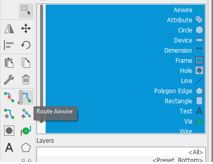
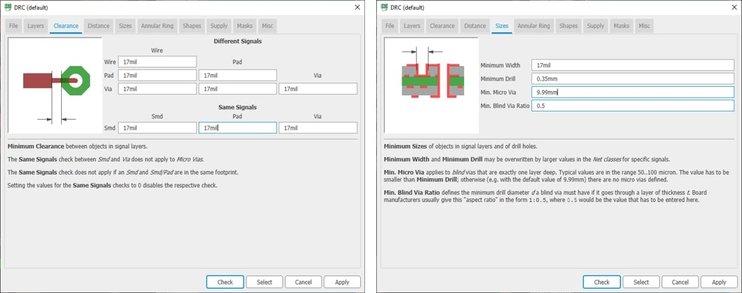
and then clicked on the DRC icon on the left tool bar. This tool is the design rule check, and it checks the design and routing based on the values fed in by the user.
In this window, I changed all the values under clearance to 17 mil and changed the minimum width under Size to 17 mil as well.
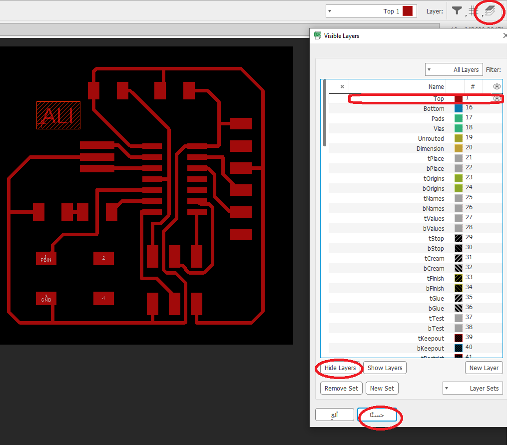
I opened ‘’Layer Settings’’ and pressed on Ctrl + A on all the layers and clicked on ‘’Hide Layers’’. After it I clicked on the ‘’Top’’ layer to make it visible on the image and then I clicked ok.
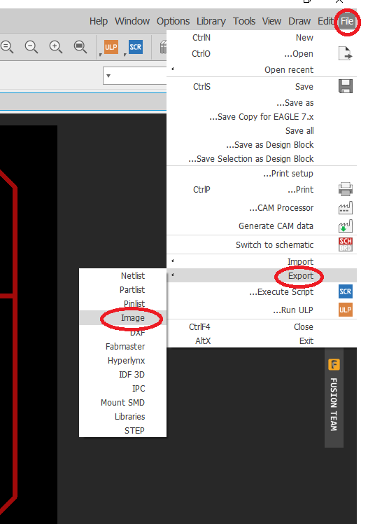
After I finished editing the picture I clicked on ‘’File’’ then ‘’Export’’ and I chose ‘’Image’’.
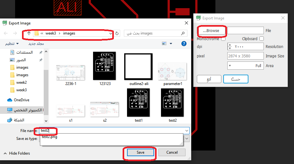
I selected ‘’Browse’’ and clicked on ‘’Week 3’’ then ‘’Images’’ and I named the picture ‘’test2’’.
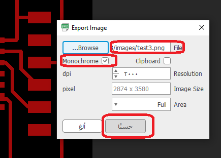
I exported the picture and clicked on the ‘’Monochrome’’ box and changed the resolution to 2000 dpi and after it I saved the image in ‘’Week 3’’.
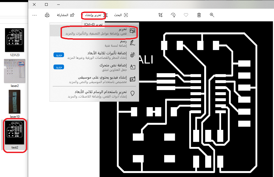
I right clicked on the image and clicked on ‘’Edit using Photos’’ and then I cropped the image and saved it as it is.
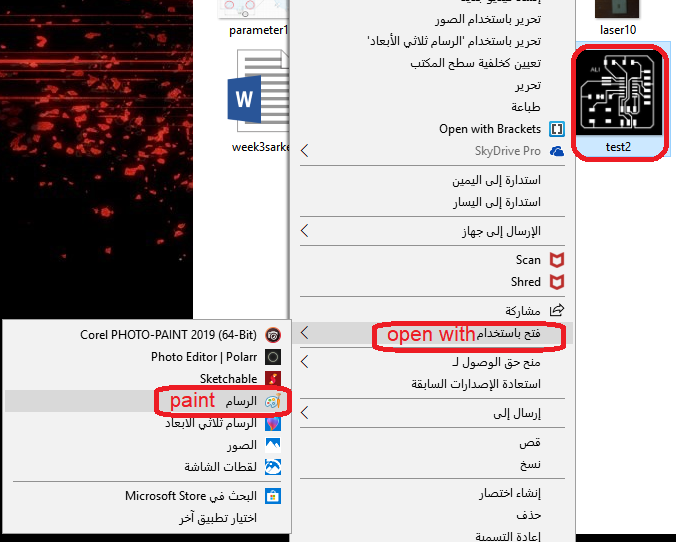
I right clicked the image and clicked on ‘’Open With’’ and then I chose ‘’Paint’’.
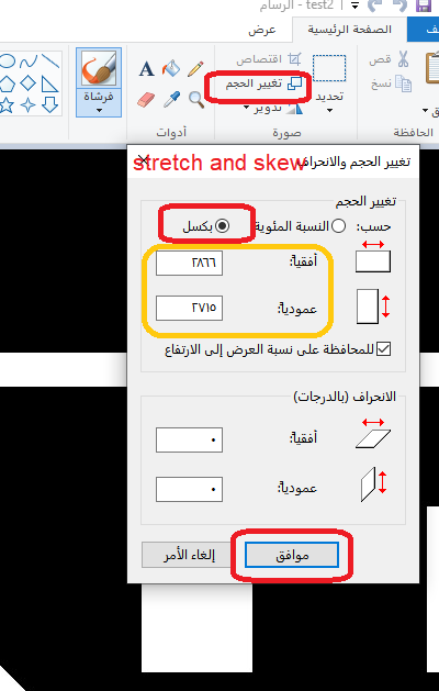
I opened ‘’Paint’’ and clicked on ‘’Change Shape’’ and opened ‘’Stretch and Skew’’. I changed the shape by clicking on ‘’Pixel’’ and then on ‘’OK’’.
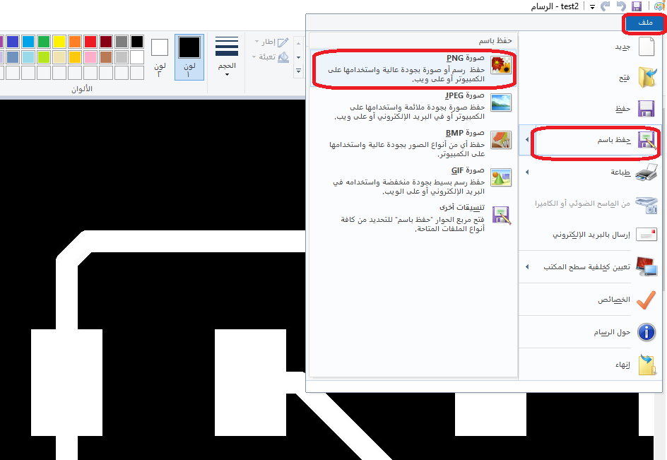
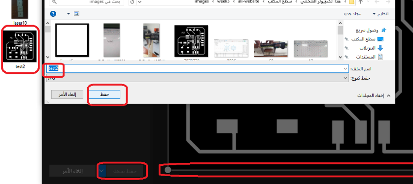
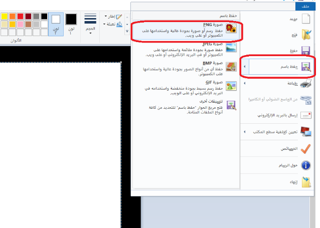
I clicked on ‘’File’’ and then on ‘’Save’’ as and I chose ‘’Image PNG’’.
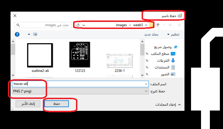
I clicked on ‘’Week 3’’ and then I named the image ‘’traces-ali’’ and saved it as ‘’PNG’’.
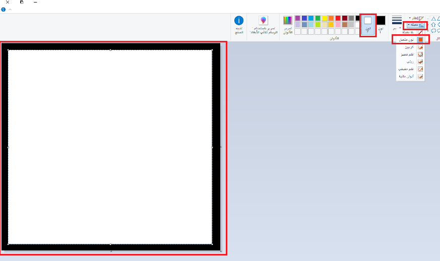
I opened the ‘’PNG’’ image on ‘’Paint’’ then I clicked on ‘’Fill’’ and chose the white color. Then I used the ‘’Rectangle’’ shape on the image to make a white box over it.
Milling and soldering process
The milling and soldering process was explained in Electronics production week
Testing my Board
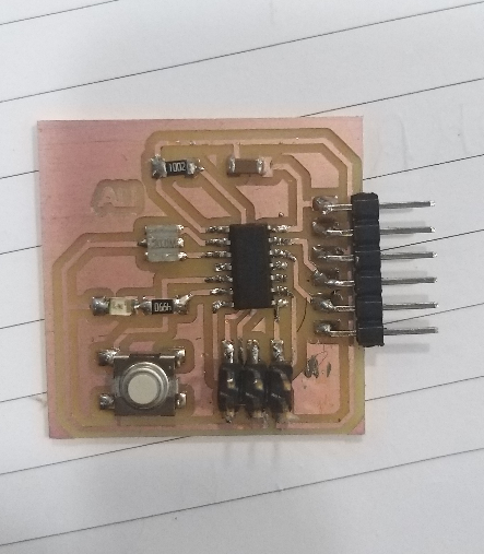
This is the final product of the board that I worked on for this assignment.
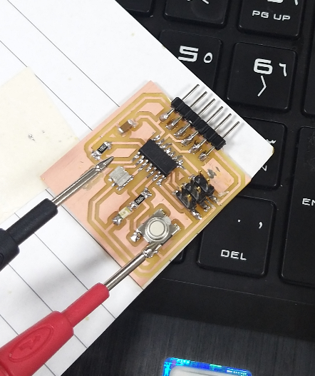
I have used the multi meter to check the circuit if it’s working or not. I have tried to check the circuit from the micro arm BB2 to resonator and it is linked to each other, and I have checked on all of the other pin on the board they are all working properly.
In this video I programmed my board and LED light worked.

This work is licensed under a Creative Commons Attribution 4.0 International License.