9. Embedded programming
assignment
Individual assignment:
Read a microcontroller data sheet
Program your board to do something, with as many different programming languages and programming environments as possible
Battery level
For this week I learned how to create my project Checking the battery using the Arduino from this website
The components I used are:
1- Arduino Uno
2- yellow LED
3- Green LED
4- Red LED
5- Ohm Resistors 220
6- 2.2k Ohm Resistors
7- Breadboard
8- Wires
9- Battery
10-Buzzer
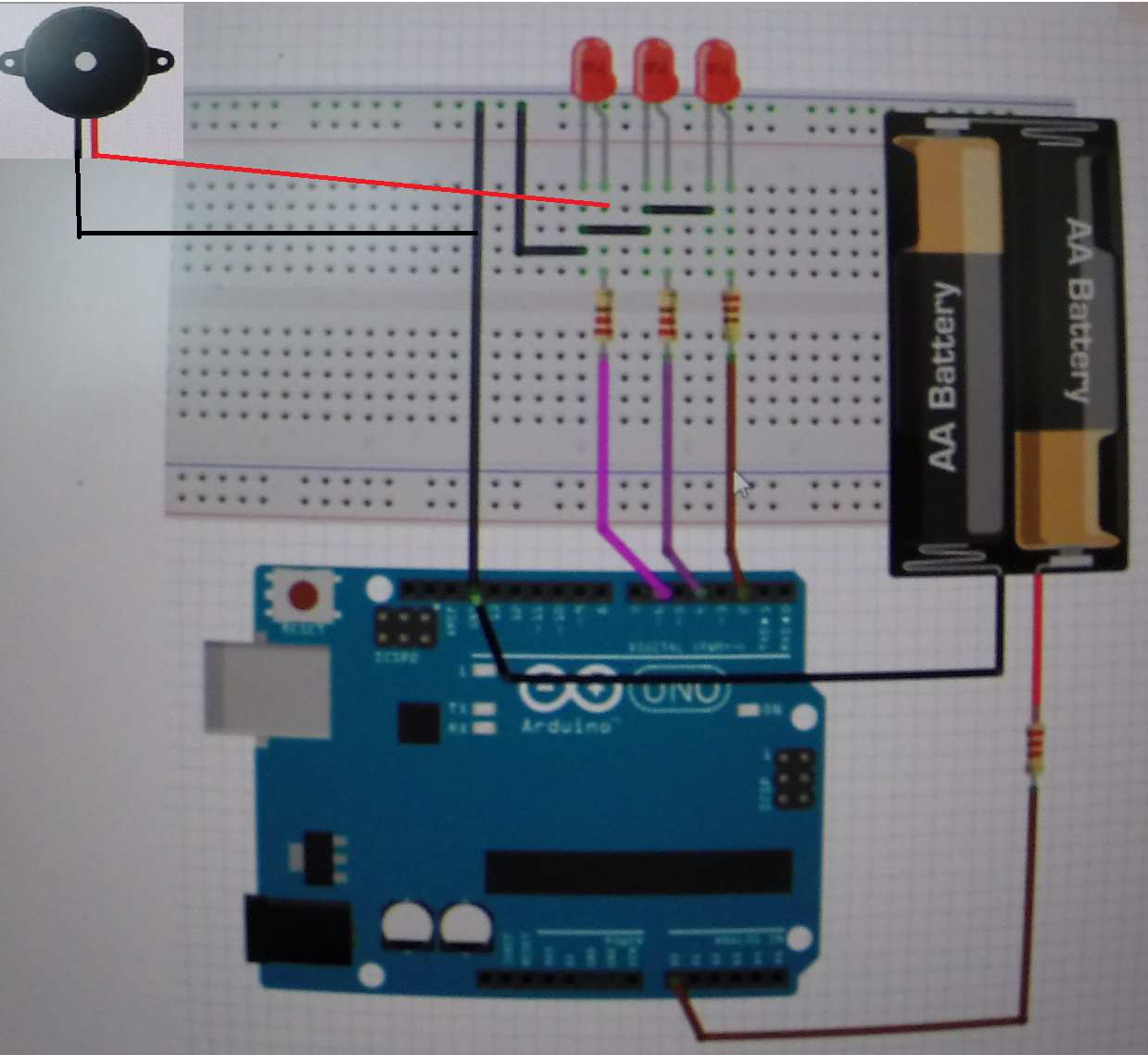
I connected all my materials together as shown in the pic below.
in digital 2 the green LED
in digital 4 the yellow LED
in digital 6 the red LED
in digital 6 the buzzer
in analog A0 battery V
code file
// new indicator
#define gled 2
// ok indicator
#define yled 4
// old indicator
#define rled 6

int analogVal = 0;
float voltage = 0;

void setup() {
  // put your setup code here, to run once:
  pinMode(gled, OUTPUT);
  pinMode(yled, OUTPUT);
  pinMode(rled, OUTPUT);
}

void loop() {
  // put your main code here, to run repeatedly:
  analogVal = analogRead(0);
  voltage = 0.0048*analogVal;
  if(voltage > 1.6)
  {
    digitalWrite(gled, HIGH);
    delay(2000);
        digitalWrite(gled, LOW);
        delay(1000);
      }
      else if(voltage < 1.6 && voltage > 1.4)
      {
        digitalWrite(yled, HIGH);
        delay(2000);
        digitalWrite(yled, LOW);
        delay(1000);
      }
      else if(voltage <= 1.4)
      {
        digitalWrite(rled, HIGH);
        delay(2000);
        digitalWrite(rled, LOW);
        delay(1000);
      }
    }
In this video shows the test
In this video I will explain the process of how the Arduino and the battery funtion with each other using the codes I inputted. I will also provide an explanation below the video.
Today we will see how we can check the electrical current on Arduino using a battery. The outputs of the board are D2, D4, and D6 while the output of the battery is A0 that we will measure. This is the sketch of the battery shown in the video and also above in the page where we have 3 resistors and 3 LED in Red, Yellow, and Green. The input is the battery while the output is the LED and each LED has a function. The Red LED means that the battery is weak, The Yellow LED means the battery is ok, and the Green LED means that the battery is very good. I used the codes that are shown above the video for input and output and I will demonstrate the Arduino board and how it works in the video.
Attiny44 Board
My instructor sent me this link here. so I can learn how to program the Attiny44 using Arduino program.
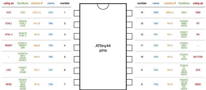
The first step we needed to take in this assignment is to read the datasheet provided here. After reading the datasheet we have a better understanding of the pins in the Attiny44 and their functions. In this picture the pin configuration is shown which made it easier for me to know the function of each pin.
Adding Attiny44 Library to Arduino
I contacted my classmates on where to get a library for my Aduino programming. So one of my classmate sent me a link so I can download the library and insert it in the Arduino code.

The video below explained to me how to add a library to the Arduino program.
Programming Attiny44
To start programming my Attiny44 boardI had the Arduino software on my computer from before so i only needed to download the Attiny44 package to program the board. After doing so I followed these steps to program my Attiny44 using FabISP as shown in the pictures below.
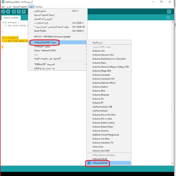
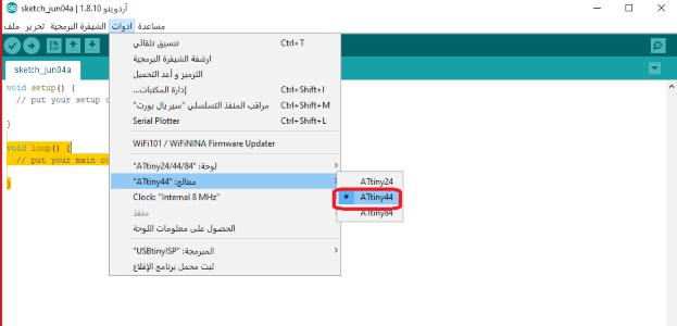
I started by adjusting the settings on my Arduino to match the settings of Attiny44 and the steps for it are in the pictures below.
Step1
Select “Tools” and then Attiny24/44/84
Step2
Select “Tools” and then select “USBtiny/ISP”

Step3
Select “Tools” and then “Attiny44”
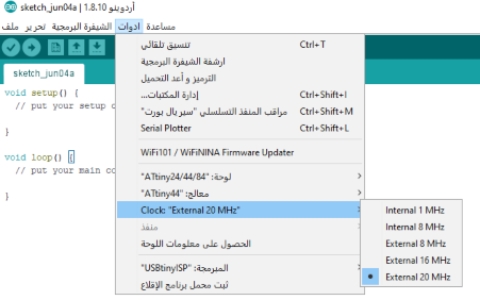
Step4
Select “Tools” and then “Clock: External 20MHz” and then select “External 20MHz”
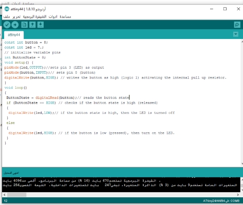
I inputted my codes into the Arduino, and the codes I used are shown below.
const int button = 8;
const int led = 7.;
// initialize variable pins
int ButtonState = 0;
void setup() {
pinMode(led,OUTPUT);//sets pin 3 (LED) as output
pinMode(button,INPUT);// sets pin 8 (button)
digitalWrite(button,HIGH); // writes the button as high (logic 1) activating the internal pull up resistor.
}
void loop()
{
 ButtonState = digitalRead(button);// reads the button state
 if (ButtonState == HIGH) // checks if the button state is high (released)
 {
  digitalWrite(led,LOW);// if the button state is high, then the LED is turned off
 }
 else
 {
  digitalWrite(led,HIGH); // if the button is low (pressed), then turn on the LED.
 }
}
End Result Video
This video shows my process of programming the Attiny44 using Arduino and the end results is that the LED light is working.
Programming Using Code Blocks and Freematics
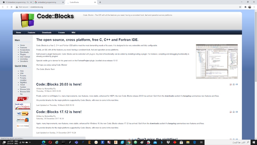
The other programming software I used is CodeBlocks which you can download here in this site. I already downloaded the program Freematicsfrom before and you can download it here from this website.
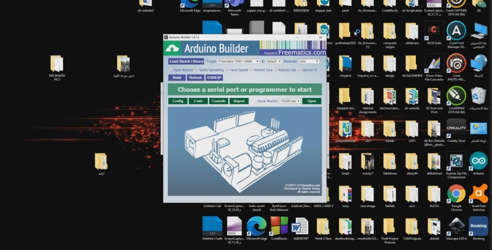
After I downloaded the software I opened it and I will start coding the board
I opened Freematicsafter downloading anf opening the application Code Blocks.
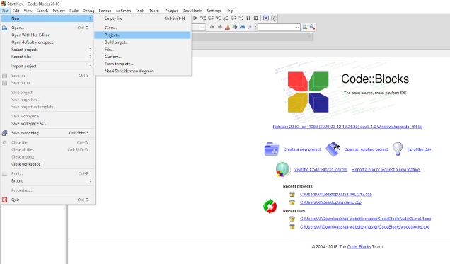
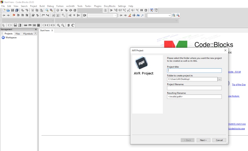
To create a new file I clicked on “File” and The “New” then “Project”.
After that we click on AVR project.
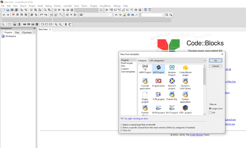
Now we name the Project Title to “testLED” and choose “Desktop” to save the location of the file.
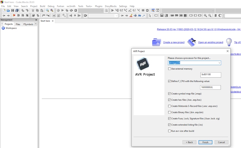
I then chose “atmega328” as the processor for this project then I click on “Finish”
Now I clicked on “Main.c” which is on the left of the program to open a window that I will insert the code on it. I made sure to type in “PB5” in line 14 to make sure that the output of the Arduino Board is on Pin 13 which is also called PB5.The code I will be using for this project is shown below.
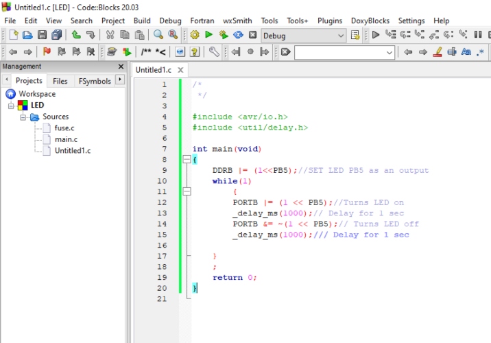
/*
 */

#include <avr/io.h>
#include <util/delay.h>

int main(void)
{
    DDRB |= (1<<PB5);//SET LED PB5 as an output
    while(1)
        {
        PORTB |= (1 << PB5);//Turns LED on
        _delay_ms(1000);// Delay for 1 sec
        PORTB &= ~(1 << PB5);// Turns LED off
        _delay_ms(1000);/// Delay for 1 sec

    }
    ;
    return 0;
}
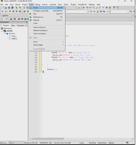
Now I have to click on “Build” then to “Build” as shown in the picture below.
Now the files have been made in the Desktop and are ready to be used. So I have to open Freematicsto start the next process.
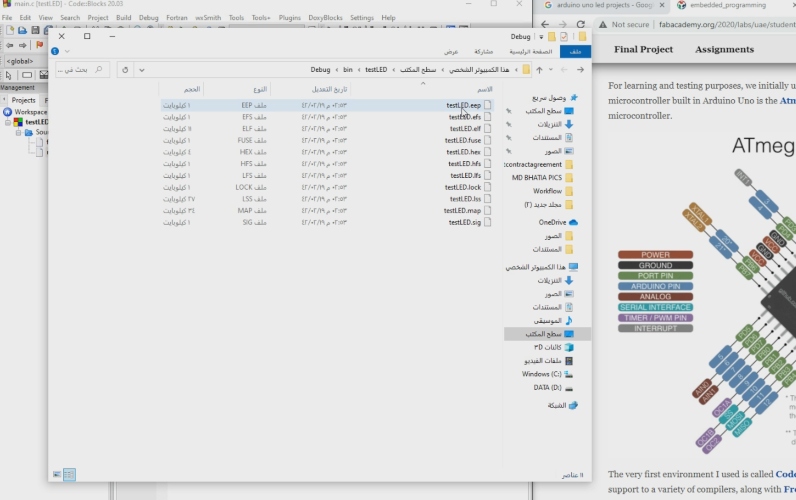
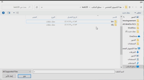
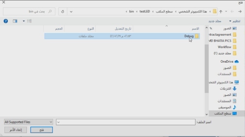
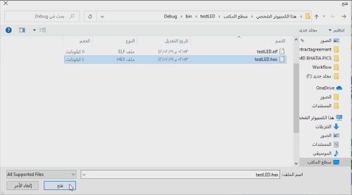
Now I opened Freematicsand clicked on Load Sketch Binary. It opens the folder and now we need to choose “testLED” and then click on “bin” and then “Debug” then I choose “testLED.hex” and the steps are shown below.
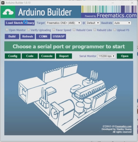
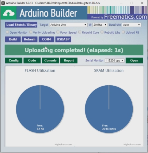
Now I opened Freematicsand clicked on Target to choose my board and I chose “Arduino Uno” and I clicked on “@” and chose 20MHz and in “Baudrate” I chose Auto. After I inputted these settings I clicked on “COM4” and the code is ready to be used on the Arduino board.
Group assignment: Embedded programming link.

This work is licensed under a Creative Commons Attribution 4.0 International License.