11. Input devices
assignment
Individual assignment:
measure something: add a sensor to a microcontroller board that you have designed and read it
Group assignment:
probe an input device’s analog levels and digital signals
Introduction
For this assignment I got the idea of making a device that can measure the distance of a person to help people be aware of social distancing. For this project I used an Arduino Uno board because of the lockdown I could not get another board.
The components I used for this project are:
1-Arduino Uno
2-Buzzer
3-Ultrasonic Sensor
4-LED Red
5-LED Green
Ultrasonic Sensor
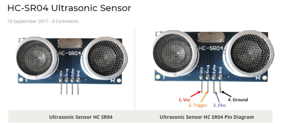
The Ultrasonic Sensor has four pins which are as follows:
VCC: The VCC pin powers the sensor, typically with +5V.
Trigger: Trigger pin is an Input pin. This pin has to be kept high for 10us to initialize measurement by sending US wave.
Echo: Echo pin is an Output pin. This pin goes high for a period of time which will be equal to the time taken for the US wave to return back to the sensor.
Ground: This pin is connected to the Ground of the system.
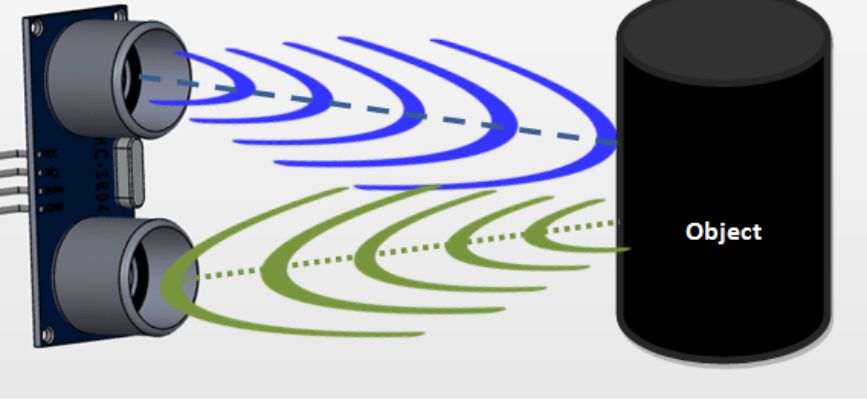
Sensor
The Ultrasonic transmitter sends a signal that continues to move until it hits an object and then bounces back to the Ultrasonic receiver as shown in the picture below. I got all the information and pictures I needed to explain the sensor here.
Assembling the Board
For the digital part of the board I connected the Vcc and Ground with a 5V from the Arduino port. For the Trigger I assigned it to digital 12 and Echo to diigital 13
The buzzer I assigned it to digital 8. LED Red digital 6 and LED Green to digital 9.
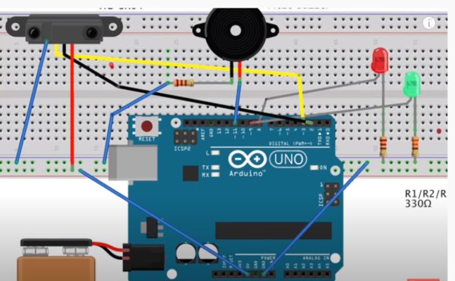
And I used the solder to join 4 wires into one connector and then I assigned those into the ground port. This way I do not have to use a breadboard to connect my components on it.
The design shown above is a demonstration of how I connected my wires to the board but without the breadboard because in the final designs photo the board is not showing properly.
I got this design and information shown above from the internet.
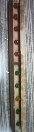
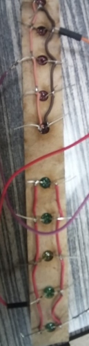
I connected the LED together using two wires and this is the wood LED holder that I will use to connect the LED light bulbs to the wires on the board.
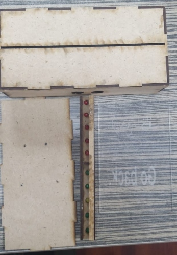
This is the final product I made the wooden box and cover that I will use to place my board inside and I also made the acrylic piece the is used to show the message “Go Back”.
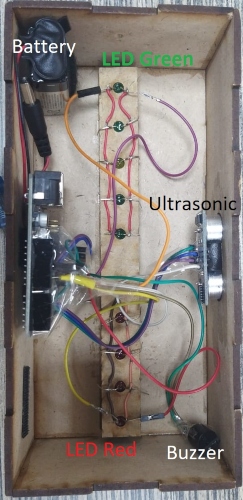
This final assembled component in the box and each part is labelled inside.
Coding
#define trigPin 12
#define echoPin 13
int Buzzer = 8; // Connect buzzer pin to 8
int ledPin= 6;  //Connect LEd pin to 6
int duration, distance; //to measure the distance and time taken
int ledPinred= 9;

void setup() {
        Serial.begin (9600);
        //Define the output and input objects(devices)
        pinMode(trigPin, OUTPUT);
        pinMode(echoPin, INPUT);
        pinMode(Buzzer, OUTPUT);
        pinMode(ledPin, OUTPUT);
        pinMode(ledPinred, OUTPUT);
}

void loop() {

    digitalWrite(trigPin, HIGH);
    delayMicroseconds(10);
    digitalWrite(trigPin, LOW);
    duration = pulseIn(echoPin, HIGH);
    distance = (duration/2) / 29.1;
    //when distance is greater than or equal to 200 OR less than or equal to 0,the buzzer and LED are off
  if (distance >= 70 || distance <= 0)
        {
        Serial.println("no object detected");
        digitalWrite(Buzzer,LOW);
        digitalWrite(ledPin,HIGH);
        digitalWrite(ledPinred,LOW);
        }
  else {
        Serial.println("object detected \n");
        Serial.print("distance= ");
        Serial.print(distance);        //prints the distance if it is between the range 0 to 200
       digitalWrite(Buzzer,HIGH);
        digitalWrite(ledPin,LOW);
        digitalWrite(ledPinred,HIGH);
  }


}
This video shows how the device is working by maintaining a safe distance.
limit switch
In my final project, I have used a limit switch as an input device. I added the switch for safety reasons, so when the camera goes down into the case, the laser cut piece hits the limit switch and it triggers a signal to switch the system off. thus preventing the camera from hitting the bottom of the case reducing the chance of any damages.
The following is the code I used for the limit switch connected to my final project board.
// NeoPixel test program showing use of the WHITE channel for RGBW
// pixels only (won’t look correct on regular RGB NeoPixel strips).
#include <Adafruit_NeoPixel.h>
#ifdef __AVR__
 #include <avr/power.h> // Required for 16 MHz Adafruit Trinket
#endif
#define LED_PIN     6 // Which pin on the Arduino is connected to the NeoPixels?
#define LED_COUNT  10 // How many NeoPixels are attached to the Arduino?
#define BRIGHTNESS 50 // NeoPixel brightness, 0 (min) to 255 (max)
Adafruit_NeoPixel strip(LED_COUNT, LED_PIN, NEO_GRBW + NEO_KHZ800);


/*Example sketch to control a stepper motor with A4988 stepper motor driver and Arduino without a library. More info: https://www.makerguides.com */

// Define stepper motor connections and steps per revolution:
#define dirPin 3
#define stepPin 4
#define stepsPerRevolution 200

int limit_switch= 1;

void setup() {


  clock_prescale_set(clock_div_1);
  strip.begin();           // INITIALIZE NeoPixel strip object (REQUIRED)
  strip.show();            // Turn OFF all pixels ASAP
  strip.setBrightness(50); // Set BRIGHTNESS to about 1/5 (max = 255)
    // Declare pins as output:
  pinMode(stepPin, OUTPUT);
  pinMode(dirPin, OUTPUT);

    pinMode(limit_switch, INPUT);
}
void loop() {

// if limit switch is not pressed turn the system on

  if (limit_switch == LOW){
  // Fill along the length of the strip in various colors...
     colorWipe(strip.Color(255,   0,   0)     , 50); // Red
    delay(2000);
    colorWipe(strip.Color(  0, 255,   0)     , 50); // Green
    delay(2000);


    // Set the spinning direction clockwise:
  digitalWrite(dirPin, HIGH);

  // Spin the stepper motor 1 revolution slowly:
  for (int i = 0; i < stepsPerRevolution; i++) {
    // These four lines result in 1 step:
    digitalWrite(stepPin, HIGH);
    delayMicroseconds(2000);
    digitalWrite(stepPin, LOW);
    delayMicroseconds(2000);
  }

  delay(1000);

  // Set the spinning direction counterclockwise:
  digitalWrite(dirPin, LOW);

  // Spin the stepper motor 1 revolution quickly:
  for (int i = 0; i < stepsPerRevolution; i++) {
    // These four lines result in 1 step:
    digitalWrite(stepPin, HIGH);
    delayMicroseconds(1000);
    digitalWrite(stepPin, LOW);
    delayMicroseconds(1000);
  }

  delay(1000);

}

// if limit switch is pressed turn off the system for emergency
  if (limit_switch == HIGH){


  colorWipe(strip.Color(0,   0,   0)     , 50); // Red


   for (int i = 0; i < stepsPerRevolution; i++) {
    // These four lines result in 1 step:
    digitalWrite(stepPin, LOW);
    delayMicroseconds(2000);
    digitalWrite(stepPin, LOW);
    delayMicroseconds(2000);
  }

}}


void colorWipe(uint32_t color, int wait) {
  for(int i=0; i<strip.numPixels(); i++) { // For each pixel in strip...
    strip.setPixelColor(i, color);         //  Set pixel’s color (in RAM)
    strip.show();                          //  Update strip to match
    delay(wait);                           //  Pause for a moment
  }
}
    strip.show(); // Update strip with new contents
    // There’s no delay here, it just runs full-tilt until the timer and
    // counter combination below runs out.
    firstPixelHue += 40; // Advance just a little along the color wheel
    if((millis() - lastTime) > whiteSpeed) { // Time to update head/tail?
      if(++head >= strip.numPixels()) {      // Advance head, wrap around
        head = 0;
        if(++loopNum >= loops) return;
      }
      if(++tail >= strip.numPixels()) {      // Advance tail, wrap around
        tail = 0;
      }
      lastTime = millis();                   // Save time of last movement
    }

This work is licensed under a Creative Commons Attribution 4.0 International License.