4. Computer controlled cutting
In Computer controlled cutting week, Hashem explained to us the different types of laser machines by presentation and we started working on different kinds of laser cut machines. Each one of them has a different propose and use.
Some of the laser cut machines we worked on are as follow:
-
Engraving
-
2D Cut
-
Pressfit Kits
Introduction:
We started learning how to cut by using laser, the speed of the cut, and the power we use in cutting the objects. They taught us on how we can manage the machine and how to operate it on different kinds of material and the shapes we can make on the settings.
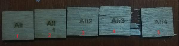
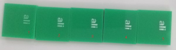
Engraving started with me using the laser machine on a small square shaped piece of MDF that has a thickness of 3 mm. I engraved my name on five pieces of MDF and numbering each one starting with one and ending with five. Each one has a different laser power and speed in cutting the pieces of MDF.
We can use the laser machine on many different kinds of material and in my assignment I used small pieces of MDF to show the power and speed of the laser as it is required in the assignment.
My first try using the laser cut machine
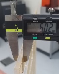
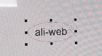
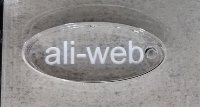
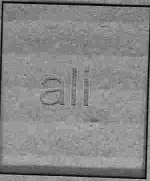
After my instructor explained to us the laser cut machine, I worked on my first test which is creating an acrylic piece. I chose the acrylic piece and its thickness which is 6 millimetre and started cutting it in an oval shape. After that I engraved my writing ‘’ali-web’’ on the piece.
Learning about kerf
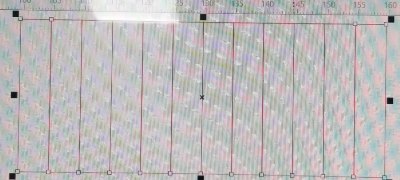
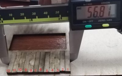
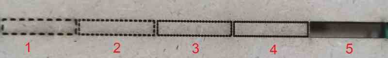
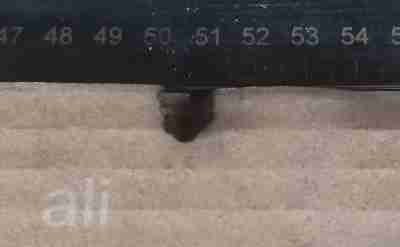
I tried on the Universal Laser System machine onto a piece of MDF 3 mm in thickness and cut the MDF into twelve equal pieces. The kerf of the MDF is found by taking 60 mm 56.81 then divided by 12 pieces and the kerf is equal to 0.266 mm.
Machine procedure
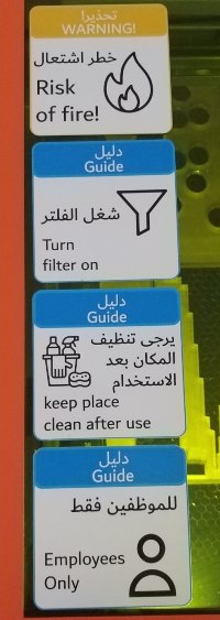
While working on the laser machine I read the safety rules that are shown below and took the steps needed to make sure I am working in a safe place for me and my classmates.
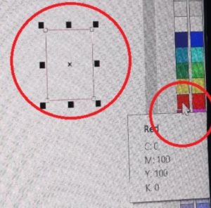
I opened the software Coreldraw and created a rectangle shape for testing. I right clicked on the Red colour and it the shape to red.
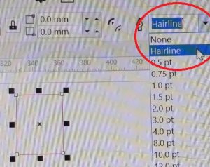
After assigning everything in the cut settings I choose the hairline setting as shown below.
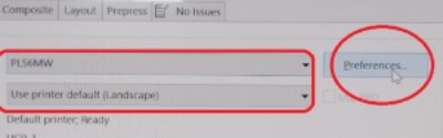
I pressed on Ctrl + P to check the laser machine name and then click ‘’Preferences’’.
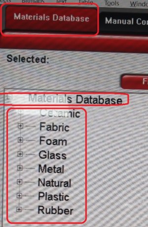
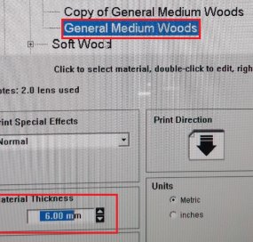
I clicked on Material Database and then I chose the material ‘’Natural’’ then ‘’Wood’’ then ‘’Medium Wood’’ and then ‘’General Medium Wood’’. After this I chose the Material Thickness which is 6mm.
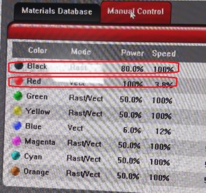
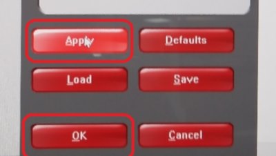
I clicked on ‘’Manual Control’’ and chose the right settings for ‘’Cut’’ and ‘’Engrave’’ after it I have to click on ‘’Set’’ if I have changed some settings to use, but if I haven’t changed the settings for the laser I directly click on ‘’Apply’’ and ‘’Ok’’.
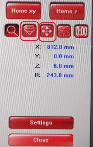
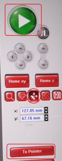
I then clicked on the ‘’Laser Position’’ button to adjust the position on the laser onto the material and moved it then I clicked on the ‘’Picture Position’’ button to know the starting point for my image so the laser can cut or engrave. Then we click on Play button and the laser machine can start its process onto the material.
Testing materials
In the picture below you can see the difference in the graving of the text on the wood and acrylic material from the power and speed of the laser. Each piece has its setting when engraved the text on as explained below:
General medium woods 6.mm.
1- The cut power is (%100) and the speed is (%1.3) PPI (300).
2- The cut power is (%80) and the speed is (%1) PPI (300).
3- The cut power is (%70) and the speed is (%.5) PPI (250).
4- The cut power is (%50) and the speed is (%1.3) PPI (200).
5- The cut power is (%40) and the speed is (%1.3) PPI (300).
6- The cut power is (%100) and the speed is (%40) PPI (500).
7- The cut power is (%100) and the speed is (%30) PPI (500).
8- The cut power is (%80) and the speed is (%.40) PPI (300).
9- The cut power is (%50) and the speed is (%20) PPI (500).
10- The cut power is (%40) and the speed is (%10) PPI (500).
The best setting for laser cutting is number (1) speed of the laser is (%100) and the power is (%1.3).
Acrylic 3mm.
1- The speed of the laser is (%80) and the power is (%100)
2- The speed of the laser is (%70) and the power is (%100).
3- The speed of the laser is (60%) and the power is (90%).
4- The speed of the laser is (55%) and the power is (90%).
5- The speed of the laser is (55%) and the power is (100%).
The best setting for cutting acrylic 3mm is speed of the laser is (%80) and the power is (%100).
Group assignments.
For the group assignment i want to testing the PPI . Our work as a group can be found on this page .
Testing PPI
I tried the setting for PPI in the laser machine () on a piece of MDF that has a thickness of 3mm and started with
1- The power of the laser is (%50) and the speed is (%1.9) PPI (%10)
2- The power of the laser is (%50) and the speed is (%1.9) PPI (%20)
3- The power of the laser is (%50) and the speed is (%1.9) PPI (%30)
4- The power of the laser is (%50) and the speed is (%1.9) PPI (%40)
5- The power of the laser is (%50) and the speed is (%1.9) PPI (%50)
cardbord
In this picture I burned the cardboard because settings that I needed to change the speed and power of the laser. The settings were in the Material Database and I chose the Cardboard and chose the thickness was 6mm but I didn’t change the setting from the Manual Control and burned the material. I asked my classmates about the setting for the cardboard and then I took the information and inputted it in my settings and the result is shown below.
The setting for the correct for cardboard is:
Engraving setting: Power (20%) and the speed (100) and the PPI (500)
Cutting setting: Power (80%) and the speed (7.0%) and the PPI (300)
Pressfit project
I used Fusion 360 app to make the shape for press fit pieces by drawing a square shape and making the slot height for it. I had a problem so I texted my classmates on the Slack app to ask for help. One of them replied and gave me the solution by making 4 slot heights at a time. It worked for me and I finished the shape.
I used the laser cut machine to make a press fit that would fit onto each other by clipping them together. I made 9 circle pieces and 8 square pieces from a MDF. After I found the kerf I took the number 3mm minus it with the kerf (0.267mm) and the result is 2.734 mm. This way the MDF pieces will press fit into each other.
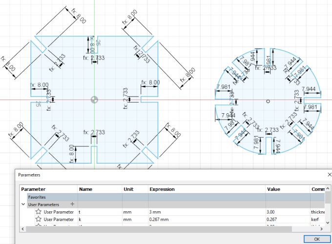
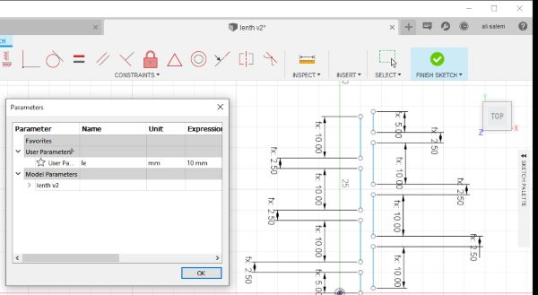
a parametric design is where fixed values are set to the features of the design, so that modifications on the design can be made by only changing these values.
I used the ‘’Parameters’’ for this sketch and the lengths are shown below:
Le / 4 = 2.5 mm
Le / 2 = 5 mm
Le = 10 mm
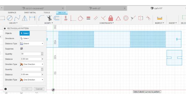
I used the ‘’Rectangle Pattern’’ to make this model and added the quantity is 30.
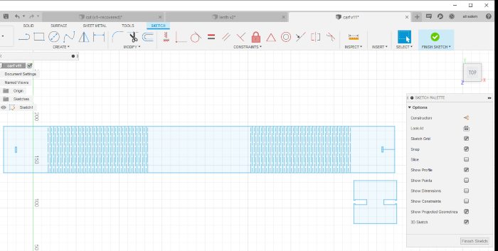
This is the final sketch I made of the model.
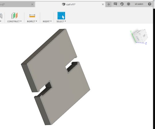
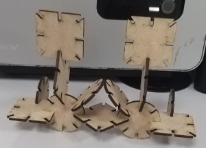
I chose the ‘’Snap Fit’’ model to use for this model.
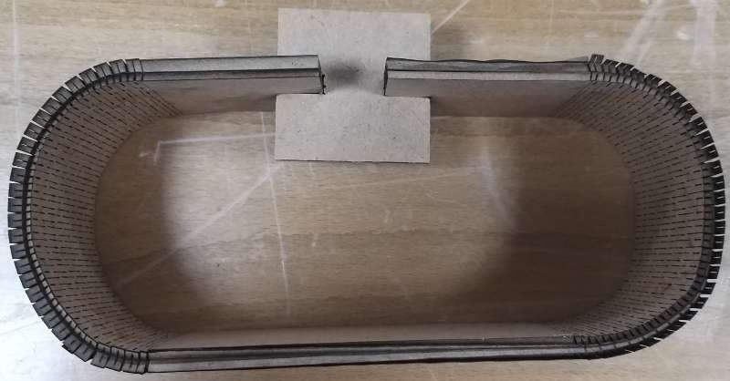
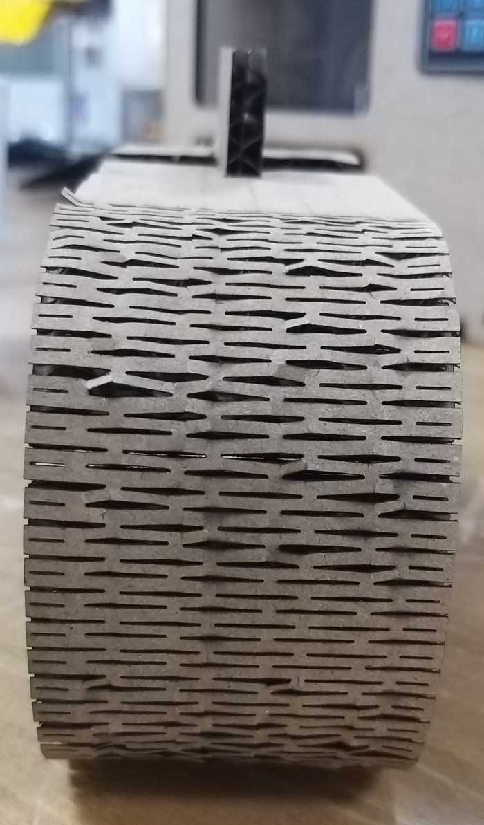
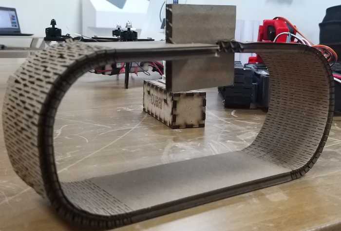
I used the machine and made this cardboard flexure model using these settings:
• Cutting setting: Power (80%) and the speed (7.0%) and the PPI (300)
After I used the machine, the final product is shown below.
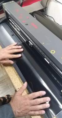
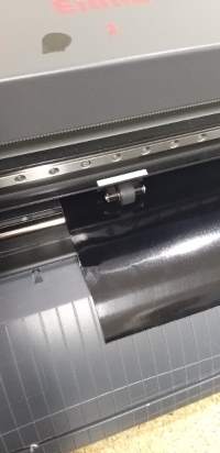
Using Roland CAMM-1 GS-24
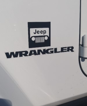
I started working on my sticker and I chose the official Jeep logo for my assignment. There are many programs that we can use to make stickers but I chose Corel Draw as my program since I know how to use it. To start making my sticker I need to start adjusting the vinyl cutter. The vinyl cutter I am using is called Roland CAMM-1 GS-24. I placed the vinyl roll onto the vinyl cutter and made sure the roll is over the sensors to vinyl cutter. I placed the roll straight onto the lines shown on the vinyl cutter but the piece of the roll was short in width so I couldn’t chose my setting to print the sticker. I threw away the piece of vinyl and took a larger piece and switched on the machine and it is ready for the command.
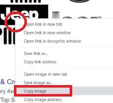
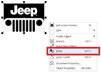
I opened Google Chrome and searched for the Jeep logo and opened images. I right clicked the image from the internet then I copied and pasted it in Corel Draw. The link of the image is shown here
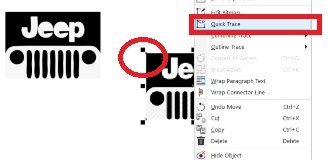
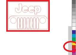
I right clicked the image and selected ‘’Quick trace’’. I have deleted the original picture and then I selected the quick trace and right clicked the red colour and it showed the trace in red that means it is ready to cut and I kept the black part of the image without any colour.
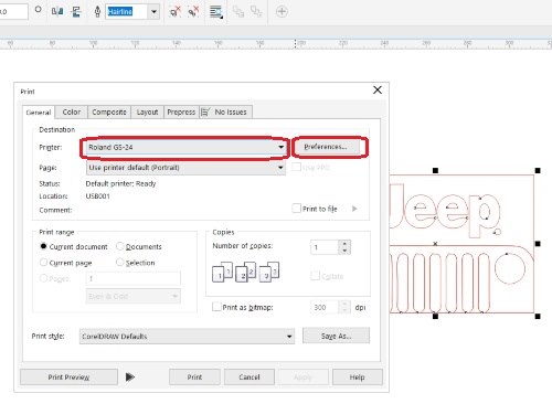
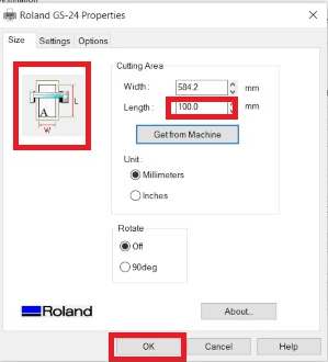
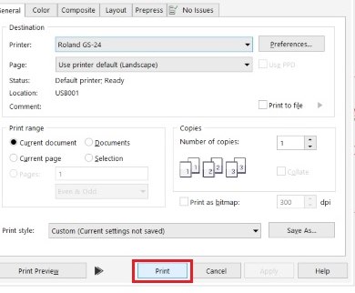
I pressed on ‘’Ctrl + P’’ and the printer window opened and I chose the right printer and clicked on ‘’Preferences’’. I adjusted the settings of my sticker and the real size of the image is 66 mm and I chose 100 mm in length. For the width I clicked on ‘’Get From Machine’’ to automatically set my width and then I clicked on ‘’Ok’’.
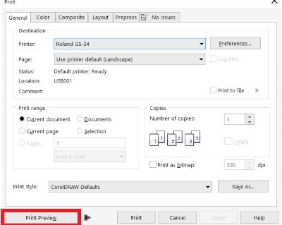
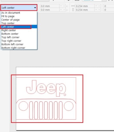
I clicked on Print Preview and a screen showed up on where I want to print the image on the roll. I chose ‘’Left Center’’ as shown below. Then I clicked on ‘’Print’’ and it started to cut the sticker.
I took away the sticker piece that we didn’t want and we added the visible sticker that will stick onto the original Jeep logo sticker and now it is ready to be used.

This work is licensed under a Creative Commons Attribution 4.0 International License.