-
00. FA20 Hyunho
-
01. Principles and Practices, Project management
-
02. Computer-Aided design
-
03. Computer controlled cutting
-
04. Electronics production
-
05. 3D Scanning and printing
-
06. Electronics design
-
07. Computer controlled machining
-
08. Embedded programming
-
09. Input devices
-
10. Applications and implications
-
11. Output devices
-
12. Interface and application programming
-
13. Invention, intellectual property, and income
-
14. Networking and communications
-
15. Molding and casting
-
16. Wildcard week
-
17. Mechanical design, Machine design
-
18. Project development
-
19. Final Project
Week3
Computer Controlled Cutting
Group Assignment Link
Assignment
Identify and explain processes involved in using the vinyl cutter
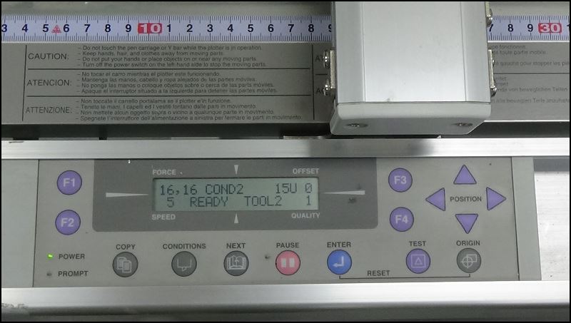
The equipment I used for plastic cutting is PRO fc2250
Use position button to adjust origin
Press position button and NEXT button together to move faster
You can use the key f1 and f2 to convert characters into engraved or cropping modes
Press the TEST button to adjust the power before the operation
Our vinylcutter uses a software called Graphtec Studio
Graphtec Studio Reference Link
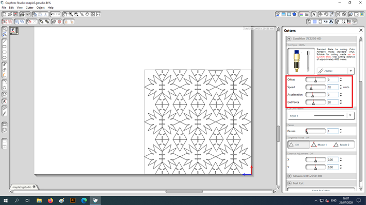
It's important to get a power value that changes the power value and cuts only the top of the sticker
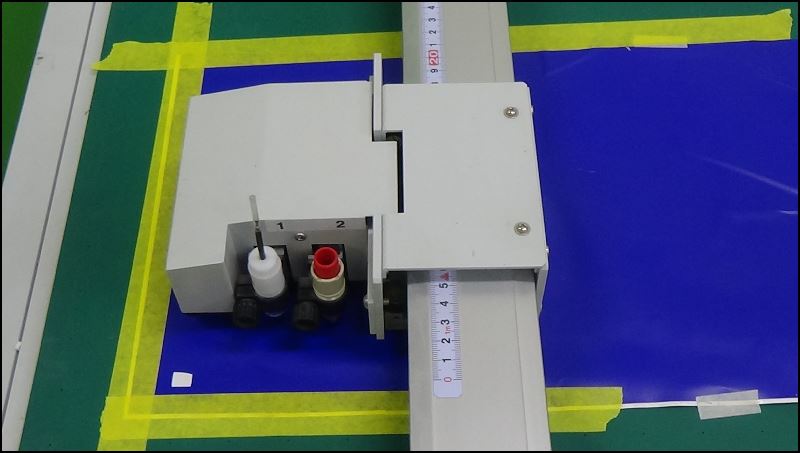
The most important thing was to have a flat sticker paper to work on
I did a test on recycled sticker
I pressed the end with a masking tape and flattened it
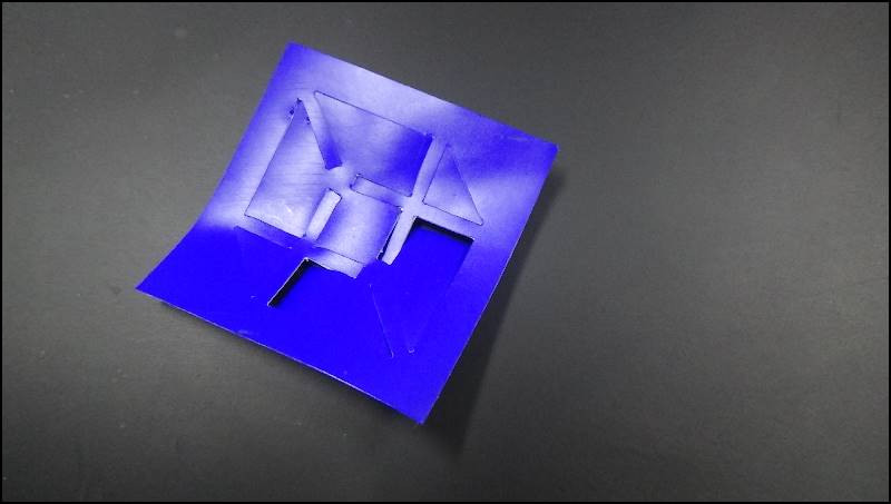
I tested it, and it was too powerful
I cut the paper below by mistake
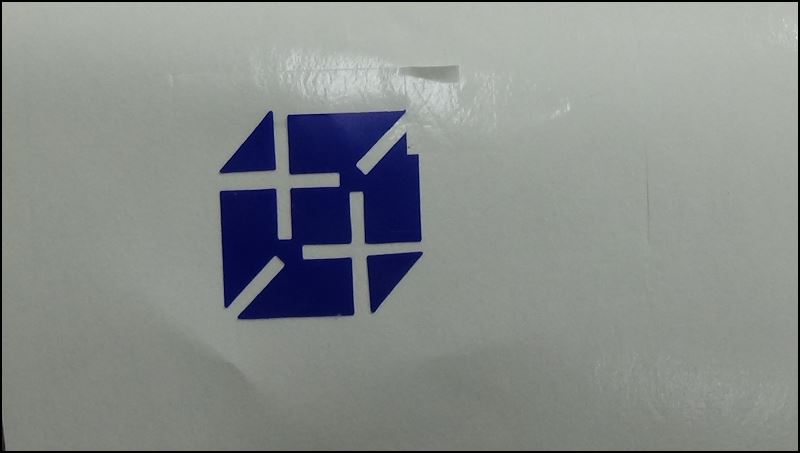
This is Innovation Fab Lab logo! (director hyebin designed it)
We're almost there!
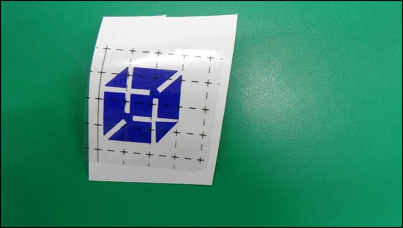
Secure the sticker to its shape using transparent grid tape with weak adhesion
Actually, this is different from the sticker on the top
I gave a better sticker to a middle school student who came to the Fab Lab
It was the most exciting moment in the Fab Academy class
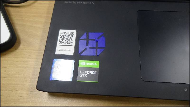
Thank you, Geforce
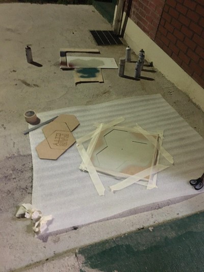
In addition, it was used to paint the fab city logo by cutting it with a laser cutter
This is the logo for the Fab City Clock Project
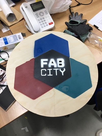
I counted the spray through the wooden board
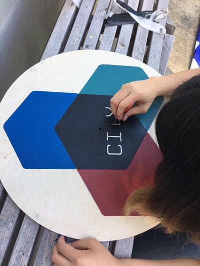
I made a sticker with a plastic cutter and sprayed it one by one
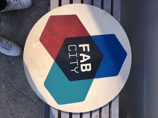
a clean result
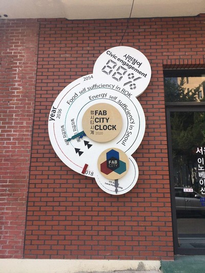
Together our team -
It's a fab city clock
Fab city clock was a project by the team at Seoul Innovation Fab Lab
Concept and artwork: 구혜빈
Web design: 김현호
Mechanical, electrical, interaction design: 호번 크레이그
Fabrication: 박석민, 호번 크레이그
Graphics: 박석민
Fab city logo: 구혜빈, 김현호
Assembly, Finish: 박석민, 호번 크레이그
Installation: Inno Park building management team (He disappeared without giving his name)
Made with support from Seoul Innovation Park for the 2020 Inno Festival
Please participate in this survey. Citizens' Participation in our Fab City Clock is going up!
Creating a Parametric Kit
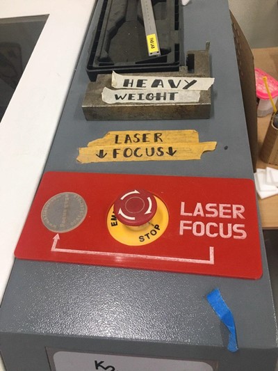
The model name of the laser cutter device I used is JG-10060
Workspace 700 X 1000 (actually 5% narrower than that)
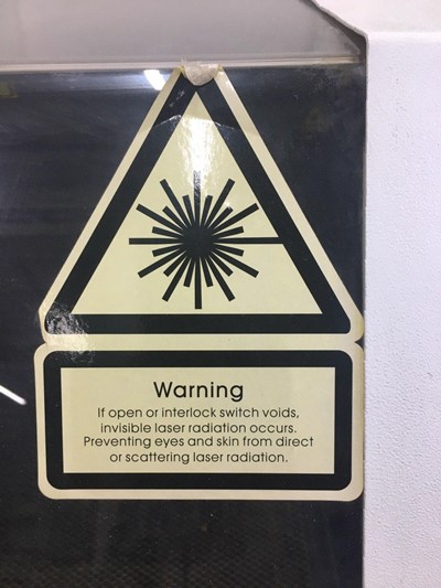
A laser cutter can start a fire in the lab
Watch the operation from a safe distance
Wear safety glasses and masks
Don't forget to check available materials and adjust z-axis according to material thickness
In case of an emergency, press the warning button and summon the manager
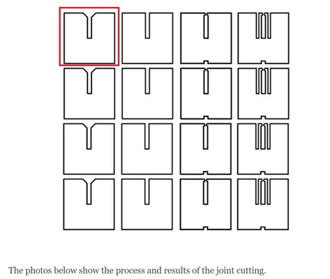
When the laser cuts through material it burns away a small amount of that material - this is called the laser cutting kerf.
The amount of kerf is dependent on the material type and thickness,
along with a couple other variables (including the lens on that particular laser cutter, air pressure, etc)
Knowing the correct Kerf helps you design a clearance
We found that the laser kerf was 0.2mm through group work
Our cardboard is 2t
So I cut a hole with a width of 1.6
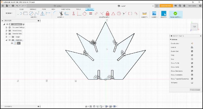
It's maple leaf
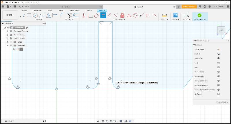
I gave 1mm fillet to make the joint easier.
I used the design in the top left corner of the group project
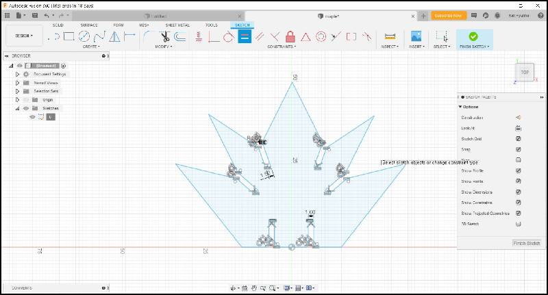
I used a mirror tool to draw half of it
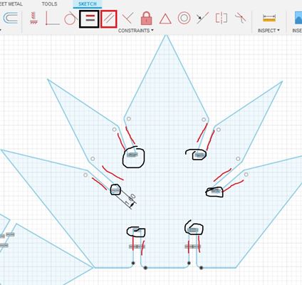
I designed a parametric design using parallel and e equal functions(black > equal, red > parallel)
Modipi has a way of setting parameter values and putting variables in it, but I've tried different methods

It's a design with a tolerance of 1.6mm
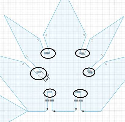
If you modify one tolerance, you can see that all tolerance values have been changed to 2mm
Transform designs into smaller ones using parametric designs,
then use laser cutters to test print the original design with large cnc such as shopbots
to quickly correct designs and reduce time to make mistakes
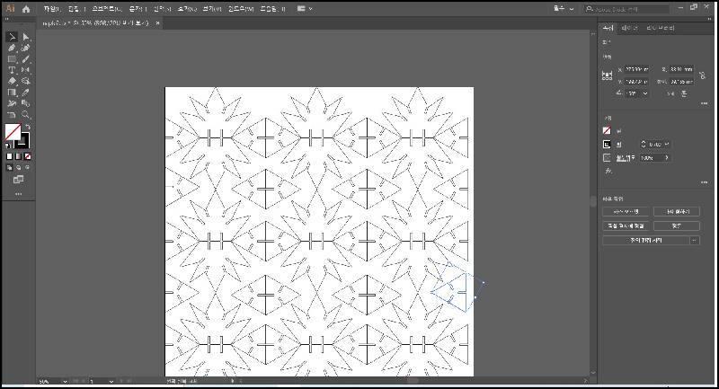
I converted it to illustration and modified it
Export to dxf
Now I'm going to cut it off with a k-2 laser cutter
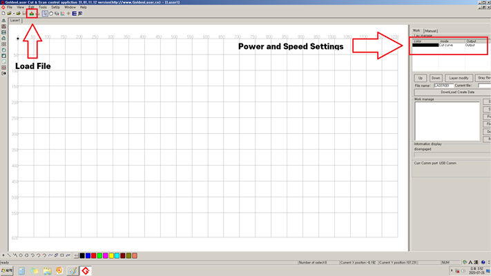
Our K-2 uses software called Golden Laser
First load the dxf file
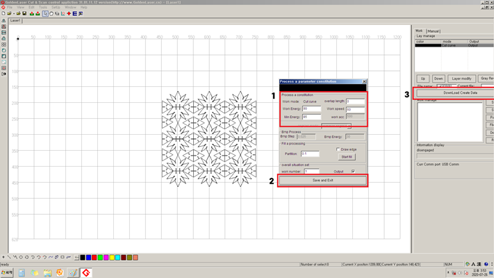
the results from the group work.
power 90 speed 60
The work was fixed with masking tape
It is important to level the material
The Z axis must not change depending on the position
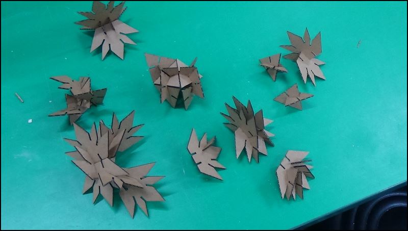
This is my parametric kit
Cutting : power 90/speed60
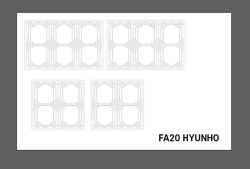
I designed the acrylic wall for the final project with an illustrator,
cut and imprinted with a laser cutter
Cutting : power 100/speed10
Engraving : power 15 / speed 150
The completed acrylic wall can be found through this link!
File
Maple Parametric.f3d file
Sticker.dxf file
hanokwall.dxf