-
00. FA20 Hyunho
-
01. Principles and Practices, Project management
-
02. Computer-Aided design
-
03. Computer controlled cutting
-
04. Electronics production
-
05. 3D Scanning and printing
-
06. Electronics design
-
07. Computer controlled machining
-
08. Embedded programming
-
09. Input devices
-
10. Applications and implications
-
11. Output devices
-
12. Interface and application programming
-
13. Invention, intellectual property, and income
-
14. Networking and communications
-
15. Molding and casting
-
16. Wildcard week
-
17. Mechanical design, Machine design
-
18. Project development
-
19. Final Project
Week9
Input Devices
Group Assignment Link
Assignment
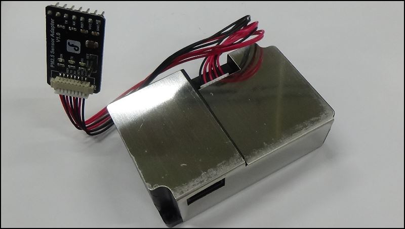
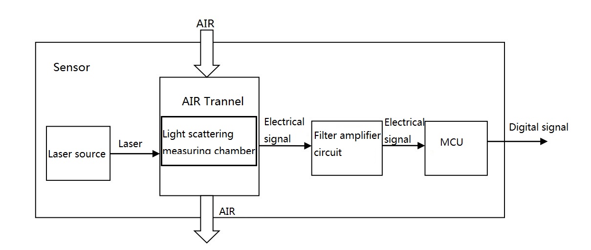
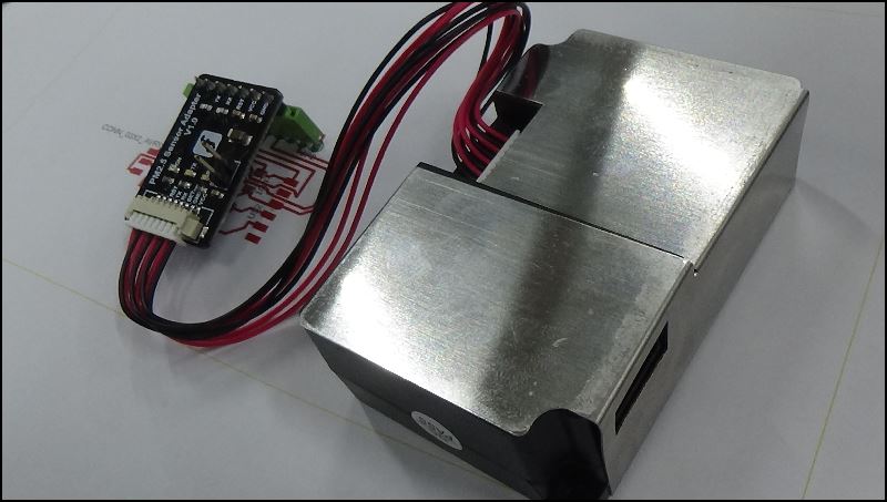
The input sensor I am going to use for my final project is a micro dust measurement sensor
Dust sensor Information Link
Specification
Power supply quality requirements
dust measuring sensor algorithm
I will measure micro dust and turn on the LED and humidifier sensor
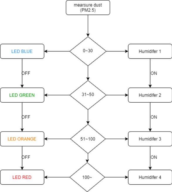
It's an algorithm for my final project
I drew it on this site
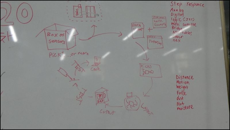
Craig's Weekend Workflow
I'm not used to electronic components yet, so I decided to go one step at a time
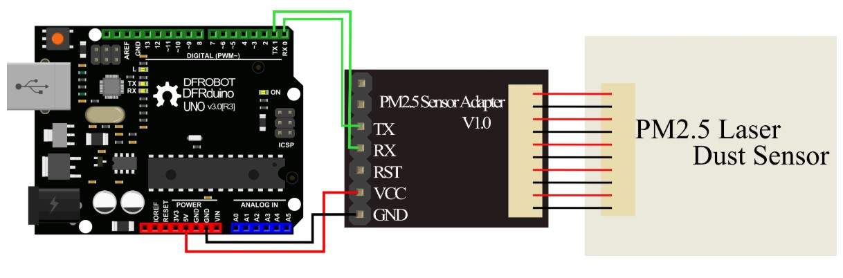
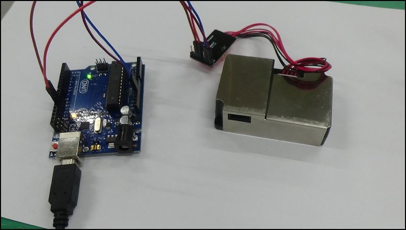
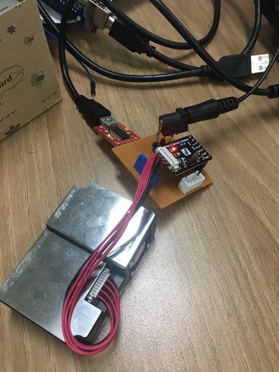
First, I tested it with the Aduino Uno board
The results were successful
When I brushed my apron off in front of it, the figure went up
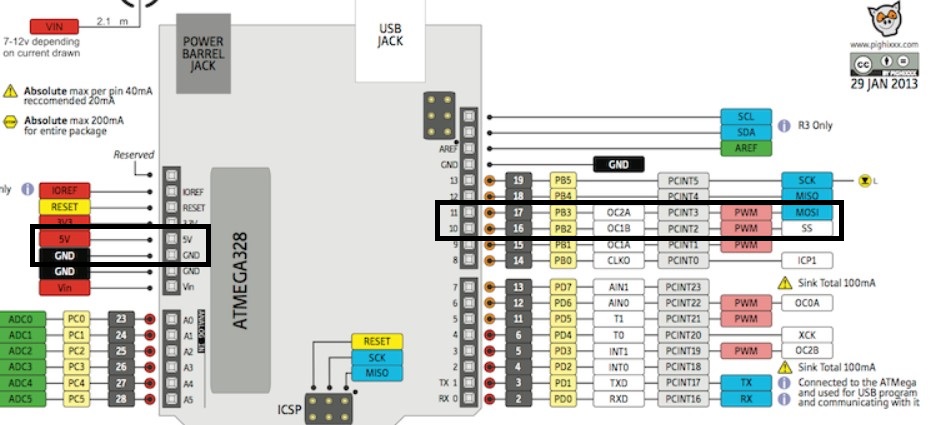
RX10, TX11
Finished drawing red lines
I learned something easier by pressing and drawing an Alt
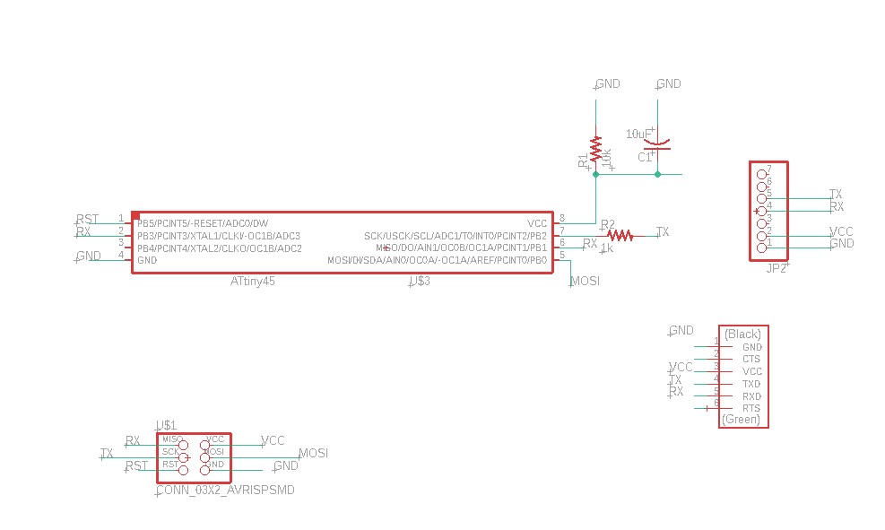
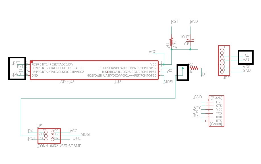
I did not know that tx and rx had to be pulled out of the new pin
So I modified it
And I downloaded the pinheader library Here
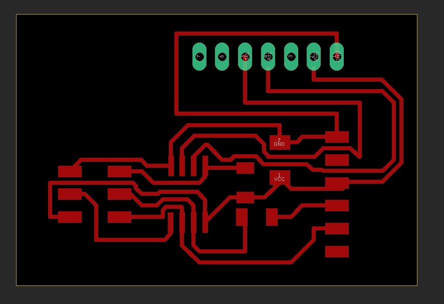
Finished drawing red lines
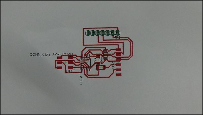
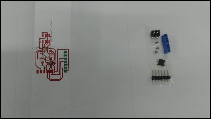
Print to Original Size
I plugged in the sensor pin and checked the size
Export gbr file using Cam processer
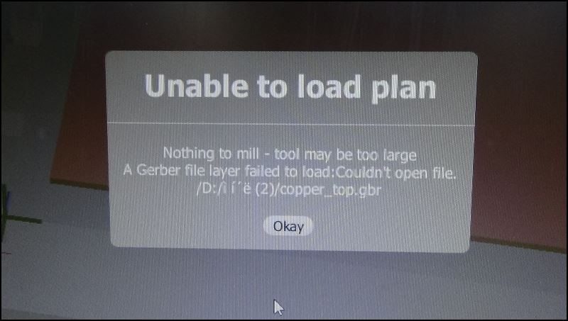
Bantam did not recognize the file
Because the folder name contains special characters
Rename it, and then activated the bantam again

And I broke the end mill
There are iron supports on the left and bottom of the bantam
So i need to modify the bantam software placements and display some design files
And I manually positioned the hole when I was drilling
I don't know how to hold it automatically in an eagle cad >>>I've explained better solutions to week6
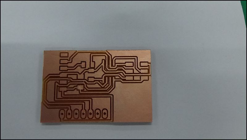
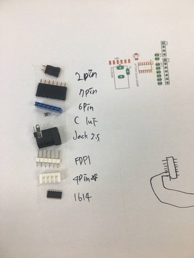
Collect components while the bantam is rotating
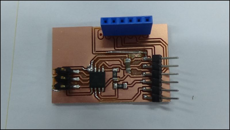
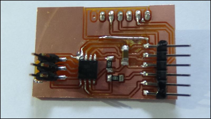
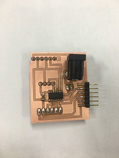
Completed soldering
The temperature was too high and the line was too thin, so I fixed it a lot
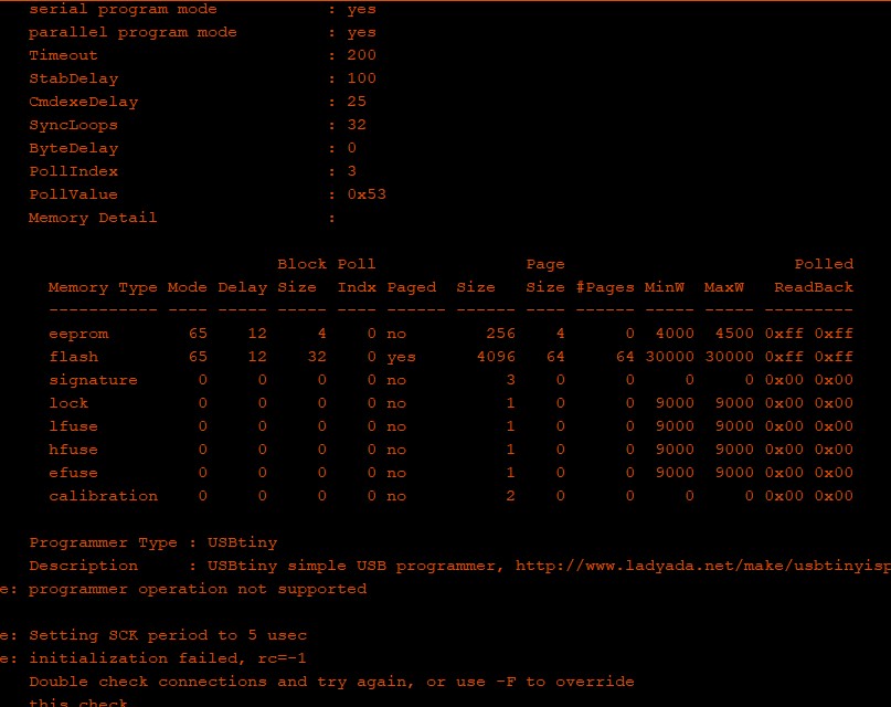
one of many error messages
I've been trying, and I know there's a problem with the board
I knew there was a fault on the board
I decided not to use isp and use UPDI to rebuild the board using programmable attiny 1614
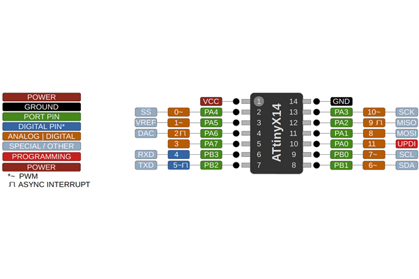
Attiny 1614 pinout
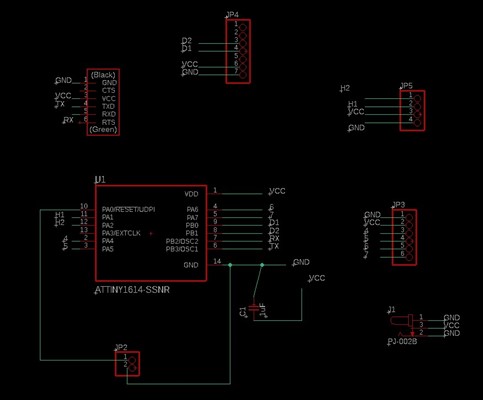
sch of my file board
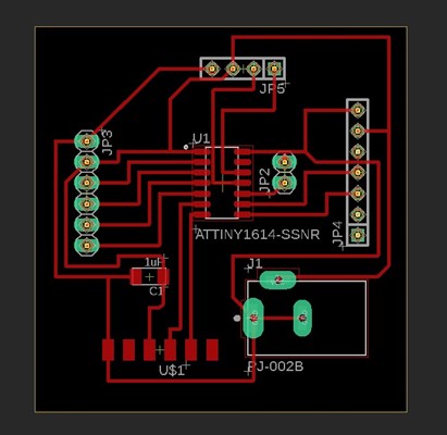
brd of my file board
This is the master board for the final project
pin11 is UPDI
pin4, 5 > FTDI
pin7, 6 > Dust sensor
pin8, 9 > Humidifier
pin 0,1,2,3 is left for for LED
The code below is an example code on the link above that modified only the pin number that matches my board
#include <Arduino.h>
#include <SoftwareSerial.h>
#define LENG 31   //0x42 + 31 bytes equal to 32 bytes
unsigned char buf[LENG];

int PM01Value=0;          //define PM1.0 value of the air detector module
int PM2_5Value=0;         //define PM2.5 value of the air detector module
int PM10Value=0;         //define PM10 value of the air detector module

SoftwareSerial PMSerial(6, 7); // RX, TX

void setup()
{
  PMSerial.begin(9600);
  PMSerial.setTimeout(1500);
  Serial.begin(9600);
}

void loop()
{
  if(PMSerial.find(0x42)){
    PMSerial.readBytes(buf,LENG);

    if(buf[0] == 0x4d){
      if(checkValue(buf,LENG)){
        PM01Value=transmitPM01(buf); //count PM1.0 value of the air detector module
        PM2_5Value=transmitPM2_5(buf);//count PM2.5 value of the air detector module
        PM10Value=transmitPM10(buf); //count PM10 value of the air detector module
      }
    }
  }

  static unsigned long OledTimer=millis();
    if (millis() - OledTimer >=1000)
    {
      OledTimer=millis();

      Serial.print("PM1.0: ");
      Serial.print(PM01Value);
      Serial.println("  ug/m3");

      Serial.print("PM2.5: ");
      Serial.print(PM2_5Value);
      Serial.println("  ug/m3");

      Serial.print("PM1 0: ");
      Serial.print(PM10Value);
      Serial.println("  ug/m3");
      Serial.println();
    }

}
char checkValue(unsigned char *thebuf, char leng)
{
  char receiveflag=0;
  int receiveSum=0;

  for(int i=0; i<(leng-2); i++){
  receiveSum=receiveSum+thebuf[i];
  }
  receiveSum=receiveSum + 0x42;

  if(receiveSum == ((thebuf[leng-2]<<8)+thebuf[leng-1]))  //check the serial data
  {
    receiveSum = 0;
    receiveflag = 1;
  }
  return receiveflag;
}

int transmitPM01(unsigned char *thebuf)
{
  int PM01Val;
  PM01Val=((thebuf[3]<<8) + thebuf[4]); //count PM1.0 value of the air detector module
  return PM01Val;
}

//transmit PM Value to PC
int transmitPM2_5(unsigned char *thebuf)
{
  int PM2_5Val;
  PM2_5Val=((thebuf[5]<<8) + thebuf[6]);//count PM2.5 value of the air detector module
  return PM2_5Val;
  }

//transmit PM Value to PC
int transmitPM10(unsigned char *thebuf)
{
  int PM10Val;
  PM10Val=((thebuf[7]<<8) + thebuf[8]); //count PM10 value of the air detector module
  return PM10Val;
}
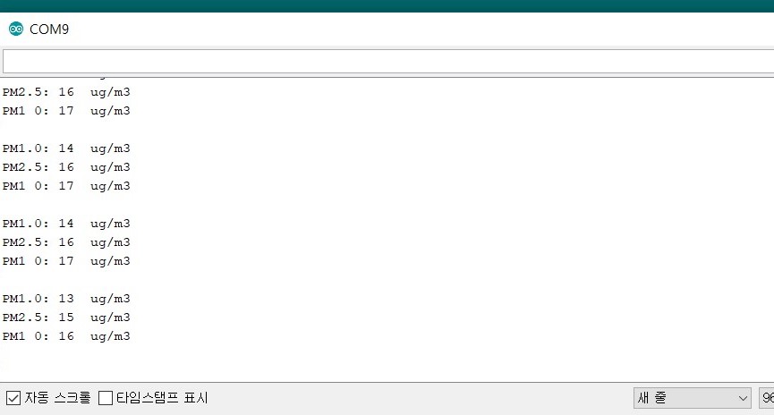
This Week Hero Video!
A video of measuring and showing fine dust with a serial monitor
File
master board.sch
master board.bdr
Code.ino