17. machine and mechanical design
machine and mechanical design
This intense assignment is sub divided into 2 parts. A brief account of the group work - where I focused on the electronic milling and testing of the stepper shield for our belt riven lazer-woodcut machine in 2020. And followed up by a 2021 “second cycle” version, with a new interface and an upgrade of the mechanism into a turning table for a rotating camera.
Machine Design assignment
group assignment - actuate and automate your machine - document the group project and your individual contribution
A machine needs to have a mechanism + actuation + automation - as a qualification for this assignment.
Mechanical Design assignment
group assignment - design a machine that includes mechanism+actuation+automation - build the mechanical parts and operate it manually - document the group project and your individual contribution
Here is the video overview of our final “machine” from 2020 with moving gears - it covers the work done individually by the 4 of us.
Aalto FabLab 2020 from Machine Building on Vimeo.
Hardware & Software
Links to some example schematics for DIY stepper motor drivers:
The TMC2208 is the StepStick we chose to use - an integrated motor driver solution for 3D-Printing, Cameras, Scanners and other automated equipment applications.The device has a step and direction interface and can be configured with digital pins.
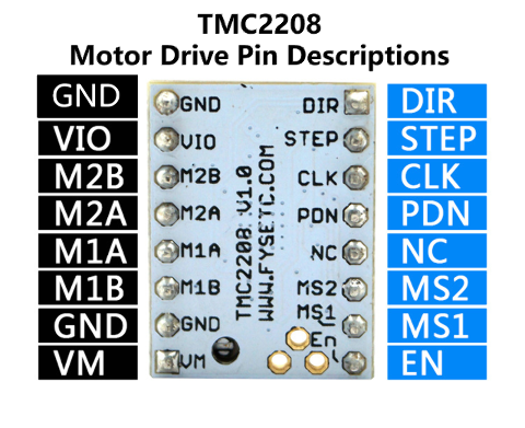
The motor current can be set on the StepStick itself, by measuring the voltage on the Vref pin (0…2.5V) and adjusting the voltage with the potentiometer.
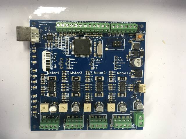
The way we are going to connect the TMC2208 stepstick to the motor, is by building a 3 layered DIY interface.
The TMC2208 sits on top of a DIY step shield, which in turn is the interface that connects the stepshield to the Arduino pins for the required direction and step pulses. The step shield also houses the other components for transforming the voltage requirements as per our calibration of the TMC2208 according to the required current (this is in turn dependent on the stepper motor we have chosen to use).
Hardware & Software setup
Where does one procure the stepper motor and machine parts? One can of course get them seperately off the shelf, however we had an upcycled option!
There were dismantled three 3d printers (Ultimakers) from which our team could salvage a number of parts needed to experiment with machine building. Our fab manager introduced us to some of the basic concepts around motors, of which he seemed to have extensive experience with - he was helpful in also making sense of the pool of parts that were laying around, that looked like a crash site.
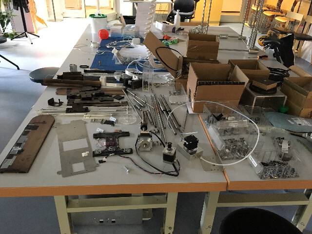
We isolated the Stepper motors from the crash site – these provide the basic motion for any of the machines - and then added accessories needed such as the belt mechanism and hundreds of bolts and screws.
Checking the RepRap wiki page, a list of parts from the 3D printer could be identified.
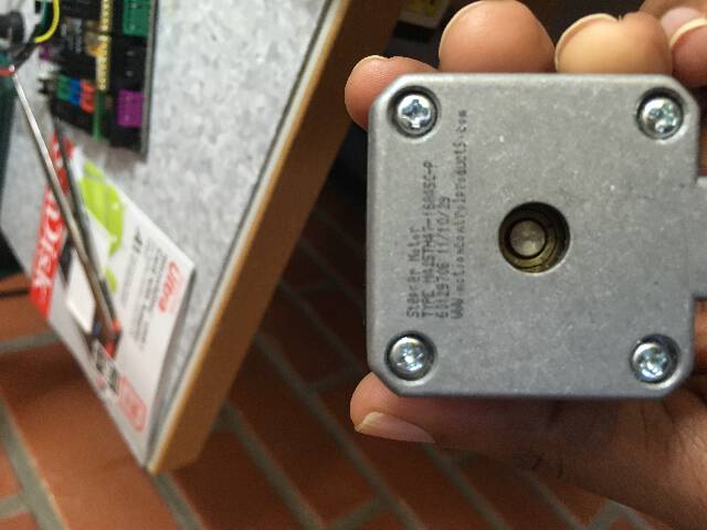
One could identify the motor by checking the model serial code printed on the side of the motor. This helps us in accessing the datasheet. An interesting thing i had noted but failed to take into account during testing is a strange rule that Steppers usually run at a higher voltage than the specs specify to get more torque. - (However overcurrent will burn the motor and the stepper drivers limit that.)
The stepper motor in question was identified as NEMA 17
Before proceeding further, I checked some online pages on the basic working mechanics behind a Stepper Motor.
The next steps were to install the software/firmare to setup Arduino.
GRBL setup
So what is a GRBL?
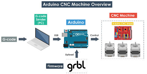
“GRBL is an open source software or firmware which enables motion control for CNC machines. We can easily install the GRBL firmware to an Arduino and so we instantly get a low cost, high performance CNC controller. The GRBL uses G-code as input, and outputs motion control via the Arduino.” - Dejan’s gerbl setup site
 - source
“The function of the GRBL firmware is to translate the G-code into motor movement - via the Arduino.”“
#
From the main github Grbl site -
“Grbl is a no-compromise, high performance, low cost alternative to parallel-port-based motion control for CNC milling. This version of Grbl runs on an Arduino with a 328p processor (Uno, Duemilanove, Nano, Micro, etc)
The controller is written in highly optimized C, utilizing every clever feature of the AVR-chips to achieve precise timing and asynchronous operation. It is able to maintain up to 30kHz of stable, jitter free control pulses.”
Hence the GRBL library makes the Arduino to work as a machine motion controller. One can send G-code to Arduino - which in turn drives the motor shield attached to it.
So, now we need to install the GRBL file into the Arduino IDE. As with all cases Arduino related, they come in “libraries”.
We need a GRBL firmware compatible Atmega 328 based Arduino board - meaning that we can use either Arduino UNO or Nano.
As a first step, we install GRBL on Arduino from github - in order to be able to install or upload the GRBL to the Arduino we need the Arduino IDE, which I already had on my computer.
However, after the installation - I tried to push the Gerbl upload file to the arduino. It did not compile and had an error that the grbl.h directory is missing.
The Arduino’s standard electrical outputs are limited, and that’s where shields come in. This way, the functionality of an Arduino can be extended . Some other examples of such shield extensions include Ethernet shields, Prototyping shields and microSD shields.
So it was decided to try and see if the open design model would work out for us. The interface for the stepper shield had a number of previously unseen parameters.
The open design stepper design file is a pretty good model as such because one can download the .rml files directly without having to adjust it using the painful MODS interface.
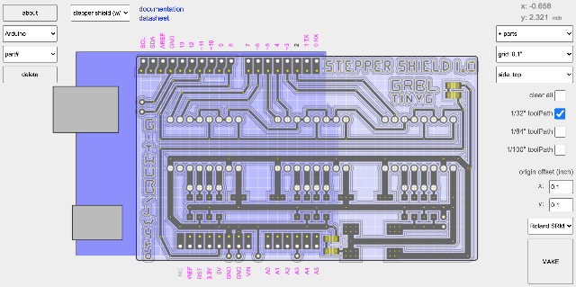
The 1/32” toolPath (0,8 mm) and 1/64” toolpath (0,4 mm) defined the tracing and cutting sections. In the choice dropdown menu, the Stepper Shield with rivets was chosen as the template.
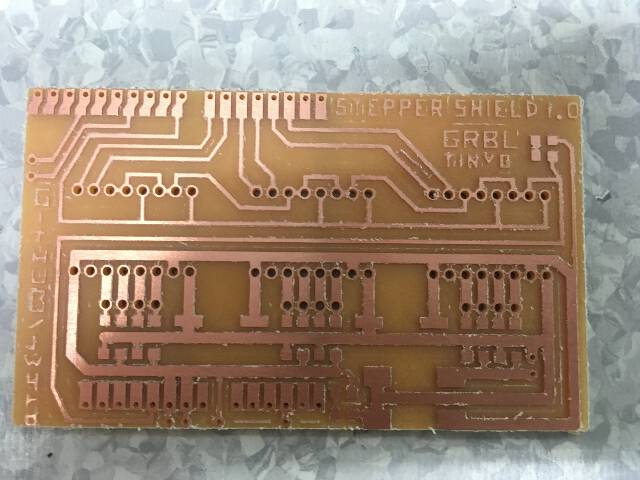
The first three attempts to print on double sided copper board using the Roland SRM-20 were dismal. The mill bits broke way too easily with the “test cut” design. The board would cut for a bit initially and after that it would lift itself away from the board even if the mill handle etc were pre adjusted to proper distances.
Three 0.4 mm bits when running the milling at varying and slower speeds - ultimately the reason was to do with the speed - however mainly it was due to the Z going 0.1 mm to deep into the board.
The issue was resolved once a distance of 0.1 mm clearance was stored into the SRM-20 as “origin” to get needed clearance. Still the speed at a high feed-rate were breaking further couple more bits - especially the 0.8 mm ones. This was resolved by turning down the milling speed between 30-40% and not going above (it broke at 50% speed) - because there was multiple traces in the design, at a low speed - the milling & drilling of the stepper shield took over six hours - so the stepper shield and a backup board took around 2 days to finish.
You can see it’s literally broken and stuck into the FR1, the MILL BIT, it is going too deep i guess..RI raised it to 0.3 mm, maybe try to set the z 0.1mm higher. So we did it so that, 1. you set the z on the surface 2. you raise 0.1mm up 3. click the set Z origin button 4. run the job this should subtract 0.1mm from the original depth 5. and reduce the feedrate before you start 6. set to 20 or even 10..
in addition to 0.1 mm Z adjustment to avoid the broken bits, some additional steps were noted: 1. set the spindle speed to HIGH 2. set the feedrate to 10-20% 3. set the Z origin on the surface 4. x and y origins obviously 5. try cutting then
However at 10-20% feedrate it was excruciatingly slow (about 3,5 hours were spent on milling this single board!).
During the milling, one matter of concern was whether the open design had a flaw in the stepper shield section where it is supposed to adapt to Arduino board with male pins.
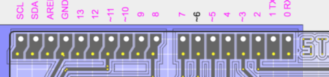
As one can see between the pin adaptor pin sub sections, there are no traces visible and it was assumed this “flaw” would make the sub sections un-separated. Our fablab master posted the issue on the jw4rd stepper github page.
However, in the milled board, the separations were totally present, one has to just stick to the 1/32” tool paths.
https://github.com/jw4rd/stepper/issues/1
Now next step was to continue with the 1 mm rivets. The rivets would hold the stepper circuit legs, as well as the jumpers.
Here there was a new issue that the holes seemed to accommodate rivets somewhere between 0.6 to 0.8 mm. One option was to use a dremmel drill to make it a bit bigger to 1.5 mm.
It seemed the reason was because the holes should be 1.5 mm. Which is puzzling because the code comes straight from the GERBL file. However, I felt by keeping the rivets in the cold storage overnight, they might just shrink a bit and then slip inside.
That technique of freezing(contracting them overnight)seemed to work ! Even though it could very well be a Placebo effect?? Essentially, with the right tools (rivet hammers) and correct positioning, ie perpendicular to the board, it was possible to rivet them in.
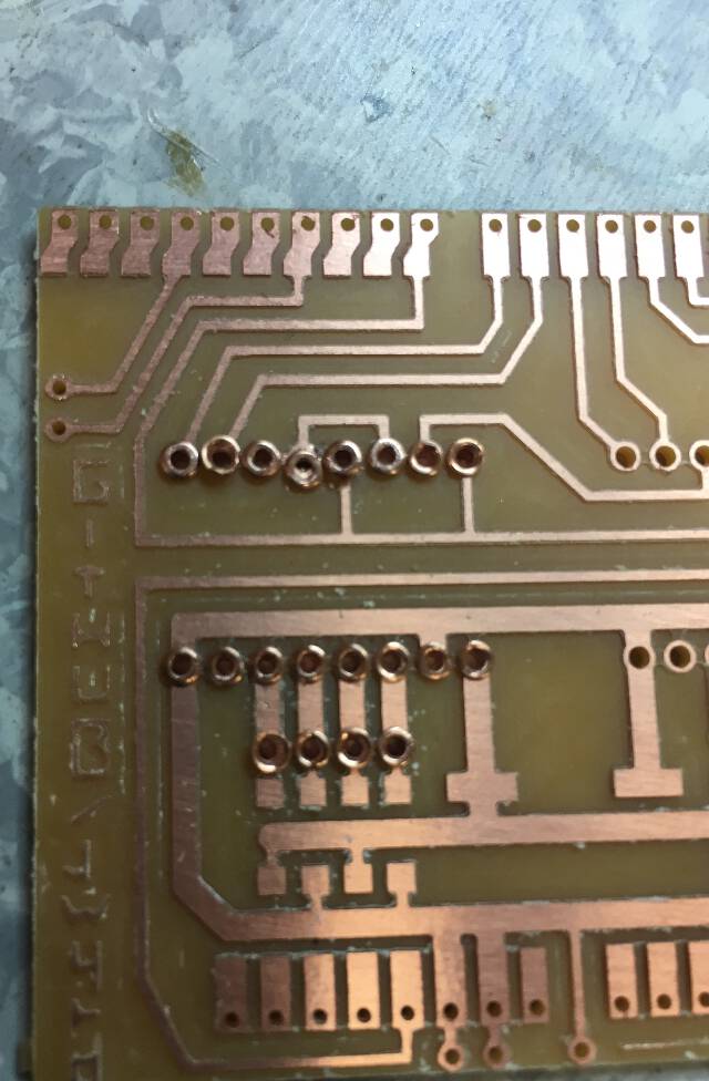
As one can notice here in above pic, the top array of rivets are the initial attempt to pound 1mm rivets into 1mm holes. The ones below are after I froze them the next day and they fit near perfectly (could also be a better technique in pushing them through).
When pushing the rivets it was important to insert them so that they are hammered in with 2 hammers. A lighter one with smaller strokes to get it in the gap, and then switch to a bigger hammer with bolder strokes to get them through. Having the rivets at 90 degrees to the board was essential as any bending would make it touch the other rivets.
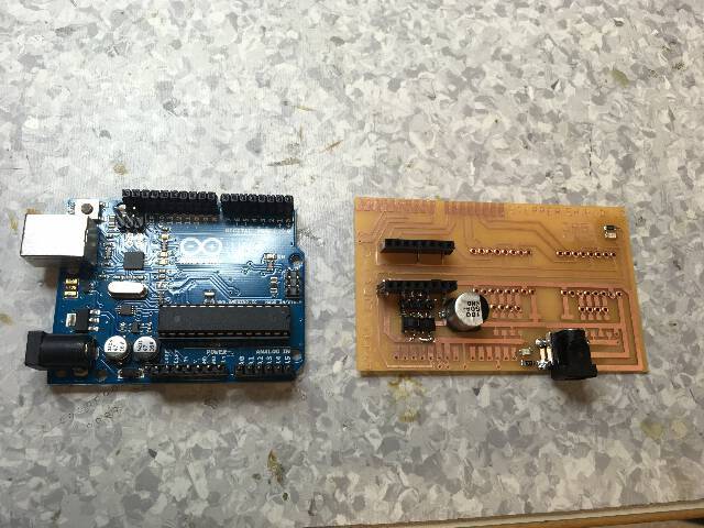
Following this, the female headers were next inserted on top of the board rivets for the StepStick & Arduino piggybacking.
========
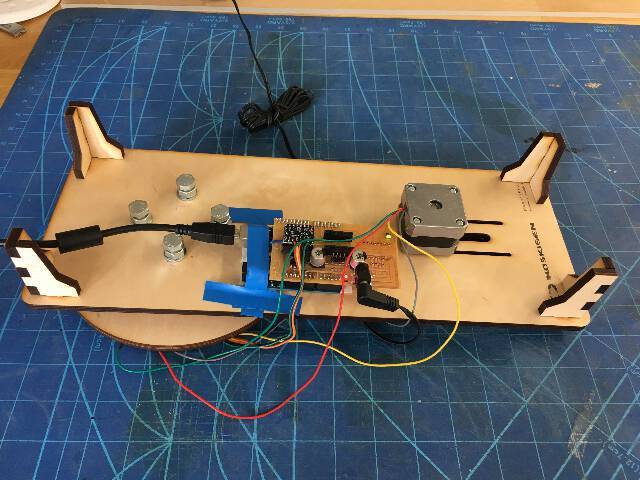
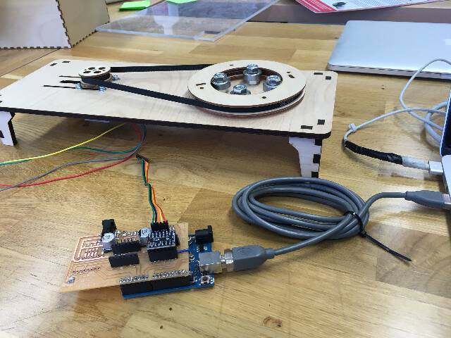
Mechanics of the Machine
The other members of the group prepared the mechanical parts of the machine in the meantime.
The wooden gears were lazer cut from wood, with a reasonable ratio for the belt movement.
Once the mechanical part was ready, it was time to test the stepper shielf-arduino-stepstick triplpe decker with a sample universal GCode sender.
steps:
The steps to building the interconnection between the web app and the motor were documented by Wen-Ting in her gitlab repository: https://gitlab.com/cv47522/nodejs-j5-arduino-stepper
Some of the key steps behind the software and interface design of our version 1.0 machine were:
- It operates on Advanced Firmata library rather than the GRBL Arduino library.
This library required is Advanced Firmata library within Arduino which has been used by Wen-Ting on our team to make her Node JS application - and it is needed to run the Arduino Uno with the Stepper shield.
- It needs Node JS to operate.Naturally, did not have Node JS - so in order to run the application, I need to download it as well via terminal. https://nodejs.org/en/
3.It then needs to run the following commands on Terminal:
[**]git clone https://github.com/cv47522/nodejs-j5-arduino-stepper.git
cd path/to/repository
ranjit-MacBook-Pro:Arduino ranjit$ cd /Users/ranjit/Arduino/nodejs-j5-arduino-stepper-master ranjit-MacBook-Pro:nodejs-j5-arduino-stepper-master ranjit$ npm i node install.js (install javascript) node webServer.js # start the server
-
The web application then was running on local server host id- http://localhost:3000/
-
From here one could access the UX, to control the RPM(Speed) & direction of this motor. The UX shows the status of the spin direction (CW clockwise and CCW counterclockwise)
2021 upgrade of the belt driven turntable machine 
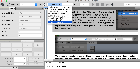
Re-Testing with GRBL, Arduino Universal GCODE sender and Motor connection
Installation of GRBL on Arduino and Universal G-CODE sender software were successful. Next step was to connect the machine, with the stepstick arduino interface and computer via USB.
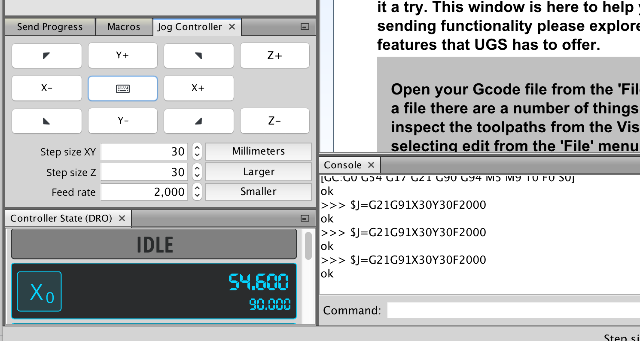
The basic test was to try to move the X axis of the motor with the G-code sender.
However, there was a strange challenge in getting the motor to work with the Universal GCODE. It did not seem to move at all.
The reason was that the pin 5 on the grbl firmware is connected to stepper shield pin 7 which handles the x direction and the pin 2 on the grbl firmware is connected to stepper shield pin 7 which handles the X step bit! So we need to modify these pins to the correct Arduino pin locations.
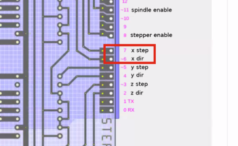
Fixing this takes a bit complicated route, where you need to flip it now on the software side - where these pins are assigned within the GRBL firmware!
ORIGINAL:
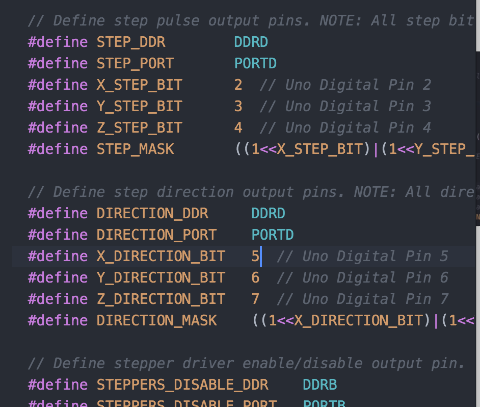
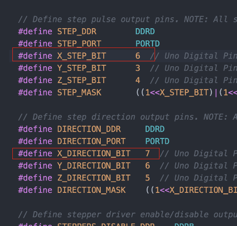
MODIFIED:
Another small error was that the tty.usbmodem1421 needed to be selected on the Universal GCODE Software instead of cu.usbmodem1421 - after refreshing.
AND NOW IT WORKS!
Fab Academy 2020 Aalto fablab from Fab Academy on Vimeo.
The evolution of last year’s machine this year was in the form of a rotating turntable - however made from LAZER CUT vinyl and using a stepper motor with a different rating - this part was designed in Fusion 360 and handled by Solomon Kiflom.
Documentation of Solomon’s Fusion 360,vinyl cutting and CNC milling can be found here!.
Also a new user interface was designed by Kitija Kuduma for controlling the stepper motors using web interface with HTML + CSS + JS. Python Server with Flask was used with jQuery AJAX to communicate using the G-Code.
Using the user interface, one could control four values at the same time - direction (clockwise vs counter clockwise), turns, speed and angle.¨
Documentation of Kitija’s software part can be found here!.
And Here is the video overview of our final “machine” from 2021!
Fab Academy 2021 Aalto fablab from Fab Academy on Vimeo.
Useful links
From online video https://github.com/fellesverkstedet/fabricatable-machines
https://github.com/gnea/grbl GRBL FILES https://jw4rd.github.io/shieldMill/ THE APP https://github.com/jw4rd/shieldMill THE DESCRIPTION
https://github.com/jw4rd/stepper STEPPER MOTOR SHIELD DESIGN
========
reference links: tiny g and the motors