Final Project brief
My Final Project is influenced by the work on sound art and media art by the movements such as E.A.T. (Experiments in Art & Technology) as well as the artistic journey in sound from artists such as Steve Reich, David Tudor, John Cage and the work in acoustic ecology by artists such as David Dunn.
David Tudor’s handmade electronic modules for the E.A.T.
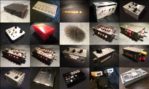
SOURCE: Reminded by the Instruments: David Tudor’s music
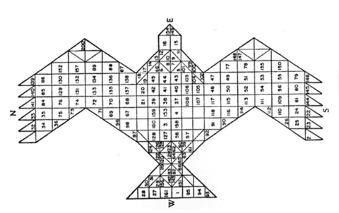
Illustration from Frits Staal, “Greek and Vedic geometry” Journal of Indian Philosophy 27.1 (1999): 105-127.
The above image is of an Agnicayana ritual practised in my hometown - considered by anthropologists as the world’s oldest living ritual (circa 800 BCe) - it is a fire altar in the form of an east facing falcon, constructed by aligning thousands of bricks of precise shape and size to create the profile of a falcon.
is a living culture a memory artefact yet?
India is a land of incredible heritage that is in danger of losing resolution and transmission due to rapidly changing socio-cultural contexts of their existence - especially being in a non digitized format. This project is thus a way of giving “living form” to heritage and ancient archival content in India, apart from just rote digitization of artefacts for a memory institution - instead of shelving them into museums “of the past”
I’ve been involved with exploring archive content for electronic & digital artwork - during that phase I visited my hometown, Kerala - where I discovered electronic mantra box had replaced traditional chants in households and temples. One can hear it in the background of this high priest’s room if you listen carefully, in the background
I immediately Picked 3 of these boxes from a temple shop and brought them to Helsinki - some of the artists loved the box and one of the bigger rock guitar Players here (Andy McCoy) borrowed it from Me and sampled it into two tracks in his long awaited latest release. Andy’s latest album 21st century rocks w/ my sampled mantra box
Electronic devices such as these are visible in temples and ritual chambers inside Indian homes and other public/private spaces with its looped chants from the box create an ambience of serenity and spiritual atmosphere. Each mantra appeals to a certain divine attribute or deity.
Next trip I went to visit a Thantri (high priest, supremely adept in tantric & mantric rituals) in Kerala, related to our family tradition. He said I can capture genuine invocations from certain priests in Tirupathi temple - that are transmitted without any distortion since thousands of years - and that would be needed to be digitized.
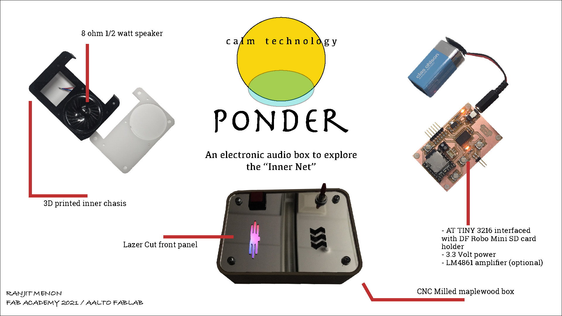
So for my Final Project - I would like to design and prototype an interactive electronic audio box, that is based on the street products in India - but taking it to a higher fidelity in terms of quality - and following at least some of the Industry protocols in assessing this quality.
but is it just another audio box I am after? some more Philosophy behind the Final Project intention - An intersection of Cybernetics, DIY makerspace and Audio Design
The other influential area for my final project is the analogous overlap between the characteristics of Cybernetic systems and Acoustic phenomena. The concepts of variety, self regulation and feedback are intrinsic to both areas.
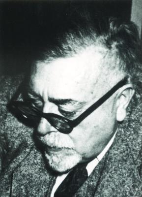
The cybernetic line of scientific thinking is driven by a string of eccentric and wonderful characters - Norbert Wiener, Stafford Beer, Gordon Pask, Gregory bateson, and so forth - of which Norbert Wiener is considered the pioneer of the cybernetic field.
The field of cybernetics is also a higher order Transdisciplinary field that deals with the art & science of dynamic systems - and encompasses technical, scientific, philosophical, creative, and critical approaches on top of the phenomenological ones.
The success of Amar Bose’s Bose audio corporation has a cybernetic lineage as well - his thesis on non-linear systems was supervised by none other than Norbert Wiener himself at the MIT.
For instance, Bose’s massively successful home audio system uses cybernetic principles - and creates an “illusion” of a huge sound by projecting & calibrating certain frequencies toward the walls close to the area the speakers are placed. Essentially, Bose invented a larger than life speaker not for the studio but for a typically reflective home environment - by understanding the non linear relationship between sound and its environment.
While I do not and cannot intend to make a high fidelity device during this time - my intention is to make an audio device that achieves a certain non-linearity and cybernetic charm if the basics work.
My inspiration is to merge the aesthetic sensibility of “teenage engineering” with what could be a mix between Alexa & an Open archive radio - where these boxes can share some yet unidentified attributes. I also happened to meet the head of Ars Electronica - who shared the interesting concept of designing an “Anti-Alexa” product - against this whole surveillance oriented, western epistemological materialistic “internet of things” - as an iconoclastic example of a counter product.
Of course without saying, the main substrate that holds this together is the totally non-linear and unpredictable yet turbocharged maker movement that is in full motion from an unknown garage in Lapland to a conscious genre in some New York loft.
Interestingly in this Neil Gershenfeld (FabLab inventor & guru of the Fab Academy) article from 2005, the prediction is that people would get empowered enough in the future to personalize their own objects - as opposed to being rejected at the market shelf. This somehow holds true to an extent in 2020 where fablabs have penetrated remotest areas around the globe. The object I have chosen to re-design is hoping to fulfil at least in part that stream of thought, as well.
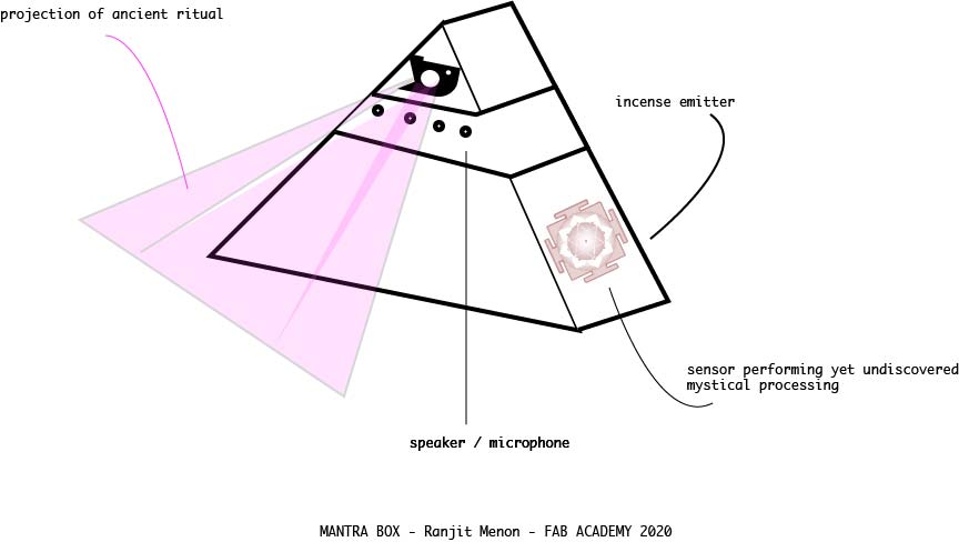
Final Project sketch - Spiritual/Calm Tech : the mantra chanting box
What are Mantras?
According to generic global interpretations, mantras are associated with “melodic phrases with spiritual interpretations such as a human longing for truth, reality, light, immortality, peace, love, knowledge, and action” (Jan Gonda (1963). The Indian Mantra. 16. Oriens. pp. 244–297)
In its original form, Mantras are energy vibrations manifest through sound - as mathematically precise sound constructs depicting metaphysical realities, they are repeated for a religious, magical or spiritual effect. The most basic mantra is ‘Aum’ also known as ‘Pranava Mantra’ for the manifestation of one supreme reality in sound form. Aum acts as a suffix or root to all other mantras - and repeated for a certain number of times - most commonly 108 times (also the number of beads on most meditation necklaces).
Most mantras are composed in Sanskrit language with slight regional variations.
Couple of examples of divine mantras
One of the most universal of all Hindu mantras, invoking the universal Brahman as the principle of knowledge and the illumination of the primordial Sun.
| sanskrit mantra |
|---|
| ॐ भूर्भुवस्व: तत्सवितुर्वरेण्यम् भर्गो देवस्य धीमहि धियो यो न: प्रचोदयात् |
| english script |
|---|
| Oṁ Bhūrbhuvaswaha Tatsaviturvarenyam bhargo devasya dhīmahi dhiyo yo naḥa prachodayāt |
| translation |
|---|
| Let us meditate on that excellent glory of the divine Light (Vivifier, Sun). May it illumine our divine intellect |
One of the most universal of all Hindu mantras, invoking the universal Brahman as the principle of knowledge and the illumination of the primordial Sun.
| sanskrit mantra |
|---|
| ॐ नमः शिवाय |
| english script |
|---|
| Om Namaḥ Śivāya |
| translation |
|---|
| salutations to Shiva / Universal Consciousness |
Mantras adopt various externalized forms too - for instance the Tibetan Prayer wheel has a mantra written in Tibetan language. This is depicted on the outside of the wheel, which is spun around - instead of oral recitation.

Tibetan Pray Wheel - source: wiki
How do technology and spiritual artefacts meet?
India and for parts of Asia that have derived a large part of its festive culture, there is a festival every other day. The use of simple technology hacks bring out creative, intricate and highly visual adornments that light up massive idols, temples, streets, houses and so on. Completely out of the import segment, this interesting blend of technology with spiritual depictions is a strong feature of the Indian local market.
For instance, LEDs and light shows are a huge part of major festivities, such as the flashing temple decorations for a South Indian deity (Ayappa):
Similarly, in the street electronic markets of India - spiritual chants and mantras have been depicted with lo-fi and makeshift audio technology.
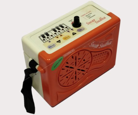
The electronic mantra box
Electronic Mantra boxes are essentially boxes with an assortment of mantras to various deities - that are played back in a long loop. Each mantra can last from 5-20 seconds - and the chants are typically played during auspicious times of the day.
It may not be as popular, expensive and flashy as the ipod - however if you look close enough behind the cash counter of a restaurant, in a small side corner of a temple or the “ritual room” of a Hindu household - you might just find this little chant box.
A typical chanting box has from three to twelve or more mantras (featured as 12 in one or 20 in one!) - that can be cycled through and played on repeat as many times as one likes. Basically each mantra is triggered as loop, and the cycling happens through a single switch.
The chanting box is closely related to another product in the Indian electronic audio market - the shruti box, usually used to provide the drone tone for classical music renditions. As such the design and manufacture of electronic instruments in India are rare and replace the analogue counterpart only if there is a clear use-case and affordability.
An electronic Shruti box for classical music from Radel electronics
There are quite a few companies manufacturing and designing interactive boxes for the local and perhaps, export market. One of them is Radel electronics, an older player in the electronic shruti and tanpura device category.
Mantra chanting boxes on the other hand, are a hyper-local phenomena. This makes their production, sourcing & design strategies deeply interesting.
google image examples of Indian mantra chanting boxes

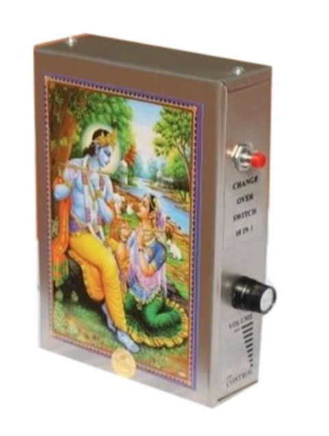
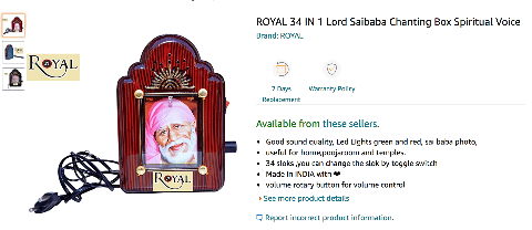 screenshot from amazon.com
The chanting boxes are typically Through Hole components, made of cheap parts in a metal casing. An example of a chanting box simple operation can be seen in the video below:
A functioning 12-in-one mantra box
mantrabox_compressed from Ranjit Menon on Vimeo.
I will be designing a more interactive and aesthetically appealing version of the current Mantra chant boxes - that will allow the user to toggle through mantras stored in an SD card - and also allowing the user to record and playback his or her own looped mantras as well.
The first thing that comes to mind with existing box designs are potential short circuits, fire hazards and blown fuses. (For eg. I was introducing the FabLab assistant to this mantra box and the power was connected to the mains while the metal housing screws was loosened a bit. The power chord blew up due to a short right next to him and he was stunned for a good ten minutes.)
So the first feature of such devices will address issues such as : - Lack of Safety
![]()
I had brought back 2 other boxes which stopped working within a month. Hence the second issue: - Short product life cycle
Studies show that “The low cost of labor to offset the high capital outlay required for automation” The reason for the shabbiness of the current product is an overall symptom of low productivity, talent & skill shortage, inefficient supply chains and low levels of supplier competence.
- Design for Affordability and Energy Efficiency By making the prototype for an affordable, yet quality household product - I am hopefully able to understand the subtle aspects of localized design needs in terms of cost, energy, resources and community context that need to be understood and included in the Key Design Features.
Additional holistic features I would like to consider are: - Generative Design with room for evolution I begin to also think along these lines: “If the device already has electronics embedded in form of memory etc., why not use it to trigger other kinds of information as well? “
- Calm Tech From the feedback generated by colleagues, the mantra box created a sense of exotic awe among artists in the west, while being a strangely utilitarian object in India. The box and its overall look and feel, should amplify both these feelings in the universal user.
The key things I would design would be in the following layers:
- The electronics - An elegant single or double sided SMD based PCB that would allow the form factor to be adapted according to context (Eg. wallplug based mantra charger, a keychain version, a piece of jewelry or a prayer ritual electronic box). The electronic components would basically be covering the SMD components as needed, ie *resistors, capacitors, LEDs. timers, amplifiers, headers, transformers as per the design.
- Electricals - A transformer that would convert 230 V AC to 3-12 V DC with maximum safety features. The design choice extends to DC power connector choices, and I should conduct further research on.
- Energy components - Battery operated, USB Charging option as well as possiblity for Solar Powered charding vs AC/DC power supply.
- Ethical Transparency - The device should be repairable and possibly upcycled - with clear information on its hazards, disposability, and a small electronics booklet detailing the parts for replaceability : while discouraging the use of counterfeit models.
- Narrative - The artefact should prominently feature a graphic narrative on the outside and interesting patterns on the PCB level that would give a metaphysical & spiritual look and feel to the device - the inside of a box for instance could have the PCBs arranged as an Indian Diety with several hands or a subtle Avatar glow around the device. A fantastic example is the Berlin Wall Distortion pedal made by a Finnish artist friend, that embodies such an approach quite well.
- Audio Components - Audio Components such as the Speakers and Mics should be well calibrated to operate efficiently and reliably under reasonably extreme conditions of usage, including environmental aspects such as dust, heat and humidity.
- Interface - If an app is needed to control the artefact, then prototype at least the basic features of being able to stop, record and playback a sound loop.
- Prototyping- breadboards, jumper wires, software for testing.
What materials and components will be used?
1. The electronics SMD components
| Component | Approx. unit cost |
|---|---|
| AVR128DB32-I/PT IC ATTINY3216-SFR IC | €0,88 - €1,70 |
| 6”x8” Single - 6”x8” Double sided board | €1,50 - €2,50 |
| LM3480IM3-3.3/NOPB voltage regulation (optional) | €0.90 |
| POT 10K OHM 1/20W PLASTIC LINEAR | 1.11 € |
| 0.1 uF capacitor * 2 | €0.16 |
| 2.2 uF capacitor | €0.16 |
| 0.47 uF capacitor | €0.16 |
| 100 uF capacitor | €0.16 |
| 0.1 uF capacitor * 2 | €0.16 |
| 1000 uF capacitor | €0.16 |
| 49.9K resistor | €0.05 |
| 10K resistor | €0.05 |
| LED RGB 4PLCC SMD | €0.35 |
| Batteries (AAA) | €0.34 |
| Coin cell battery 3V | €0.95 |
| # |
2. The electrical components
| Component | Approx. unit cost |
|---|---|
| AC/DC WALL MOUNT ADAPTER 5V 5W | €4 |
| USB to UART USB 2.0 UART Interface 16-SSOP | €1.75 |
| AC DC Connector Jack 0.70mm surface mount | €1.09 |
| SWITCH TOGGLE SPDT 0.4VA 20V | €0.90 |
3. Audio Components
| Component | Approx. unit cost |
|---|---|
| 8 Ohms General Purpose Speaker 500mW 600Hz ~ 4kHz Top Round | €2,13 |
| MICROPHONE CONDENSER ANALOG OMNI | €2,61 |
| Amplifier IC 1-Channel (Mono) Class D 8-MSOP-PowerPad | €1.09 |
| FRS 5 - 8 OHM fullrange speaker (optional) | €7,69 |
8. Prototyping components
| Component | Approx. unit cost |
|---|---|
| SPEAKER 8OHM 250MW TOP PORT 81DB | €4 |
| Breadboard + Jumpers + Wireloops | €15 - €20 |
| 10 kOhms 0.25W Trimmer | €0,96 |
| addtnl resources | links |
|---|---|
| Dropbox | [plugins/dropbox/README.md][PlDb] |
| GitHub | [plugins/github/README.md][PlGh] |
| Google Drive | [plugins/googledrive/README.md][PlGd] |
| EU India open science collaboration | [ https://euraxess.ec.europa.eu/worldwide/india/europes-global-approach-cooperation-research-innovation-india-valuable-partner] |
| Basic LM386 amp schem w bass boost | [https://www.circuitbasics.com/build-a-great-sounding-audio-amplifier-with-bass-boost-from-the-lm386/][breadboard compatible] |
| hi-quality John Broskie AMP boards | [http://tubecad.com/]+[https://glass-ware.stores.yahoo.net/newhardware.html] |
What parts and systems will be made
- The casing
- The amplifier and microphone boards
- Electronic PCB housing the main ATTiny 3216 microcontroller and Memory unit
- Housing for Speakers
Electronic Schematics
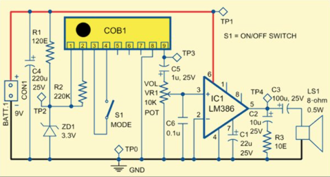
During some basic research online, I came across some of some “open electronics” schematics of these players.
So essentially, it is a simple amplifier circuit with a speaker - with a Read-Only memory (ROM) chip.
“The ROM chip is a complementary metal-oxide semiconductor (CMOS), large-scale integrated (LSI) chip.) Known as chip-on-board (COB), these boards are available in different sizes, under a blob of epoxy, with chips programmed with single or multiple mantras/artis such as gayatri mantra, ganapati mantra, krishna mantra, om namah shivaye, shri ram jai ram and satnaam wahe guru.” - https://www.electronicsforu.com/
There was a bit more detailed explanation on the choice of components and inner workings in this chanting circuit.
Most Indian mantra boxes come in a package of mantras (starts from 1 chant and go right upto 40 +, usually 7-12 in one is average ) in one package. After exploring some of the online pages in the chanting box category, it seems that most of them had a basic circuit as far as the amplifier, speaker, switching circuit goes. The mystery is in the IC chip using to store the mantra in the ROM (Read Only Memory)!
The IC is typically hidden “under a blob of epoxy” as this is probably the most sensitive part of the circuit - and needs to be prevented to the vagaries of India - from humidity, heat, serpents, falls, short circuits and so many other serendipitous “anything-can-happenings.
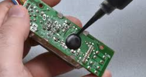
The IC chip “under a blob of epoxy”
The blob of epoxy can be seen in Chinese greeting cards and such toy-like products too, where a small loopy sound file needs to be stored and triggered.
COB or Chip-on-Board under an epoxy layer seems like a standard in these kinds of products. I did a bit of online research to know more about COB and came across this page on how COBs are made in China.
According to electronics stack exchange:
“IP protection example: until a few years ago FPGAs always needed an external serial memory to load their configuration from. This configuration could be an almost complete product design, and therefore expensive. Yet, simply by tapping the communication between FPGA and configuration memory everybody could copy the design. This can be avoided by COB-ing FPGA + memory together under a single epoxy blob.”
“The blob is an epoxy resin to protect the IC with the bonding mechanically; the bonding wires are very thin (as thin as 10𝜇m for gold wire) and therefore extremely fragile. Another form of protection it offers is reverse engineering protection. This is not fool-proof (the resin can be removed), but it’s a lot harder to reverse-engineer than simply desolder an IC.”
In the case of my mantra box, I have no intention to get paranoid about the IC chip, and would like to keep the electronic design as “open source” as the thousands of years old mantras I am using within them.
Aspects of the Design
Preliminary rough Box sketch
Casing Design
- Explore enclosure features such as Snapfit and a bracket for securing all the components.
- Secure the PCB to a 3d printed casing, securing it with placeholders for screws.
- Possible back cover snapfits, and features a spot/exposure for a bigger speaker.
- If there is an add-on memory such as micro sd card slot, then plan a nice cutout section for the element.
- Possible toggle switch to power the device on and off
- can use a lipo battery that charges via usb - unless it is solar powered or AA batteries
- The faceplate can be designed to accommodate a custom keypad
The above interesting approaches to casing design comes from Adafruit - who have been giving ideas and open design for casings around which their off-the-shelf components could be fixed. eg:
other “guerilla style” ideas include:
Design for Mass Manufacture
The PCB design and the casing would be the major design challenges that are to be addressed for the FAB Academy prototype. However, the bigger realities around mass manufacturing is also a case in point to be considered.
According to The Hitchhiker’s guide to PCB design, Design for Excellence (DFx) is one attribute of measurement for ensuring a PCB is designed for scaling up in mass production.
They include Design for Test (DFT), Design for Cost (DFC), Design for Manufacture (DFM), Design for Assembly (DFA), Design for Repair, Reuse, and Recyclability (DFR3) and many other “DF’s” that can be organized into a Design for Excellence (DFx) concept - in my case, with a special focus on DFM, DFA, and DFT.
In this way, the design can somewhat try to shadow industrial best practices to understand (not necessarily mimic) mass manufacturing processes.
The mantra box project hopefully will extend to other fields - ultimately Mantras themselves are considered as sonic forms given to various energy fields i.e. Sonification of our ecological and “invisible” environment - especially energy data.
The basic checklist for the interactive audio box includes
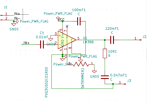
- A basic amplifier either the LM386 and/or the LM4861
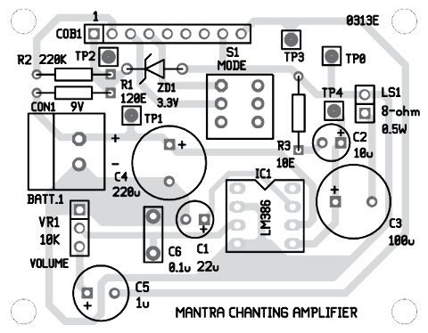
The generic Indian mantra box schematic is shown below.
- A microcontroller - ATtiny1614-SSFR for the moment
- an 8 ohm speaker
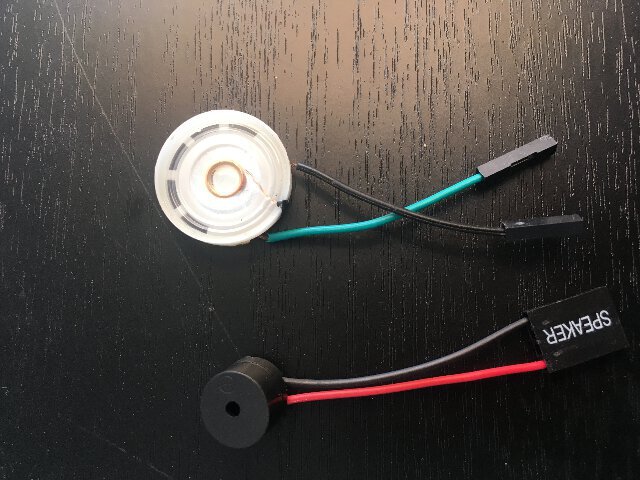
Above is an example of a prototype speaker for testing purposes.
-
a microphone capable of good dynamic range across indoors/outdoors, reflections and distances, preferably a P48 circuit
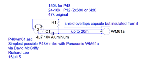
-
A CNC milled wooden shell for the electronics case
- Appropriate audio capabilities
- Energy sources - solar/battery/adapter
- a robust read and write memory capsule - SD card or something flash based
For the audio speaker and microphone benchmarks, a number of them were explored during a digital fabrication project for the EU called Furnish.
Prototyping of a basic audio amplifier circuit
The basic prototype was to start with an electronic sketch of creating a board with a basic amplifier circuit. The idea was to have the amplifier and the Memory unit on separate boards - joined with a UPDI connector with a basic TX and RX.
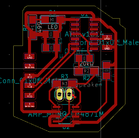
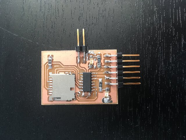
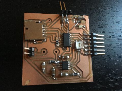
Prototyping of the basic LM4861 audio amplifier circuit to communicate with microprocessor as well as SD card holder on a single board.
simple amplifier 1614 board without memory unit
However, I managed to create a sketch of all the components onto the same board - so that the SD memory module and the amplifier/speaker circuit were on the same single sided board.
SD memory holder and amplifier on same board

The microprocessor chosen was the AtTiny 1614 - which had a 2mb storage.
The SD card - while it managed to work on one of the many boards I had milled, it had some strange grounding or magnetic problems. It was not consistent.
At this point, we might have found a replacement for the problematic SD card module.
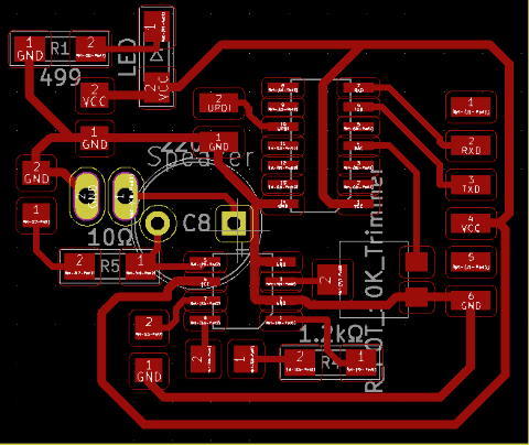
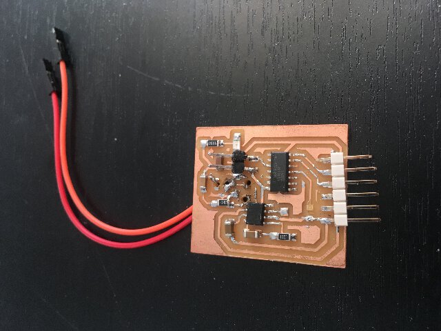
Here is a prototype single sided board that is already milled and houses the SD card holder, amplifier, AtTiny 1614, audio outputs (missing microphone input).
Since my SD card board has been giving issues and in case Audio signal noise continues to be a challenge - then as a backup, DFRobot’s DFPlayer Mini MP3 Player (a small and low price MP3 module with an simplified output directly to the speaker) will be considered. The module can be used as a stand alone module with attached battery, speaker and push buttons or used in combination with an Arduino UNO or any other with RX/TX capabilities.
The All-in-One board works inconsistently. So currently as of May 2021, , I am developing this into a modular system, separating the audio, At Tiny IC, SD card board (most likely the DFROBOmini) and speakers - this is needing mainly to preserve integirty of the audio signals.
General benchmarking
manufacturing:
SYSTEM DIAGRAM
Industrial / Mass manufacturing
In China, for instance to manufacture Digital MultiMeters - there is not one company with entire tool chain - however several sets of companies that manufacture the display, batteries, Control ICs and assembly etc.
An automated wire bonding machine that connects bare silicon to a PCB as part of the chip on board (COB) process. from Nathan Seidle's video on vimeo on Vimeo.
Rather than soldering the wires, thermosonic bonding process uses a combination of heat, pressure and ultrasonic vibrations to bond the wires. According to the blog, this is similar to how liquid solder paste holds SMD components solidly in place before they enter the reflow oven (well we do have these..!)
ideas and spinoffs
how about a black led based keychain that is anchored onto a wooden speaker box ?
how about making the box transparent ?
how about making RAIN+NATURE SOUNDS as a lovely backdrop (laid back mode) and the mantra chants in (lean forward mode)– ?
how about making a LED metronome ?
form = a 4 directional replica of brahmastanam temple ?
ending the spiritual and utilitarian in one box.
==========
DFROBOT: 29 MAY 2021
- MADE AND TESTED DFROBOT WITH EXAMPLE CODE for switching, volume, toggling and output speakers with minimal clicking - only works at 3.3 V.
- Testing LM386 THT breakdboard acc to johnaudio
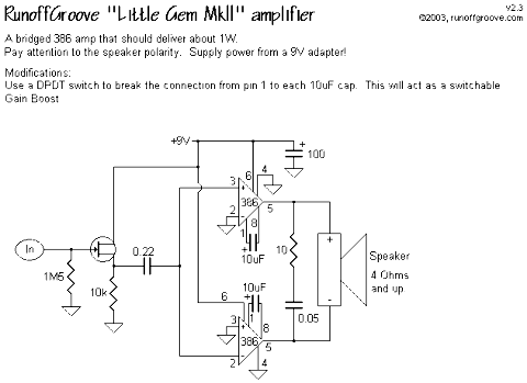
- Testing LITTLE GEM gain plus volume knob with SMD LM386mx-1/NOPB which is a CLASS AB MONO 325W 8SOIC 4.
LITTLE GEM
GAIN is set internally to 20 - res + cap at 1 and 8 increases gain from 20 to 200.
==========
JOHN AUDIO TECH: 29 MAY 2021
LM386 AUDIO AMPLIFIER & PROPER GROUND LAYOUT
- most of distortion and buzzing complaints are because of poor circuit layout.
- PCB layouts in particular need to follow some electrical and ground rules.
- good chip for building small amps, has limitations
- total harmonic distortion across power and fequency band must be under 0.1 watts for good hifi - this chip across most of it is well under 0.1 per cent, but doesnt make it across the frequency, and does better at 9V but also at 6V one gets pretty decent response - w piano or flute maybe you can detect lower levels of distortion, hence depends on music. 5.this amp should not ideally be used with 4 ohm loads.
FOR LM386 behaviours.
- Power Supply decoupling capacitor right close to the LM386 PINS!
- MANHATTAN STYLE of circuit construction not good for audio?
- power supply and signal ground flow should be kept seperate. (refer to little gem THT signal path)
show image of signal ground from the “little gem” THT board circuit line. 11.secret! “pin 4 of IC” and right at that point without any wires going forward - split the grounds of into separate ZONES. The decoupling capacitor comes in from the power source at its own inflection point at the no.4 pin. Power ground then flows to the output. MOST IMPORTANTLY THE INPUT comes off seperately at its own grounding zone, w bypass capacitor. If you look at internal circuit, the bypass capacitor and negative feedback is connected to inout signal ground. Hence, MOST IMPORTANTLY the input ground signals on left side are seperate from the power ground signals on right side.
So you dont have any of the power ground signals conducting into the input ground.
Otherwise the input clashes at the pin 4 of the chip and raises voltage at that point, and that causes distortion. Doing this will help avoid fuzziness and distortion & allow one to use it to full capability.
“pin 4 w decoupling cap, and ground for power supply onto own durection”
LM386 IS PRETTY SENSITIVE TO CRAPPY GROUNDING. HE has power supply connected to 9 V. can get 04 - 0.7 watts out of this thing if everything is connected well to 9V (w a resistor at input or so). Hearing has a logarithmic relationship so every watt rise will cause a huge increase in loudness.
9V battery gives 4-5 hours of good listening w LM386.
Amp’s internal imedance is high. 1-8 1k plus 10 mF cap is just right for headphone, music etc.
10K makes 600 MA on LED hence less drain at battery.
- make a mount for the back of the speaker with switch, LED etc.
- multi purpose, there is an insert for line in
- Little 3.5 inch speaker is not capable of efficient sound reproduction, especially the bass. Larger speakers are must for that.
- In order to move up from LM386 you need a 12 volt solution - 9V batteries have low watt-hour capactiy and will run down quickly with 5-10 watt per channel amps. Class D is great for battery use, however not idea for home DIY because of tiny surface mount chips and careful board layout needed.
- compare some layouts from here: https://www.circuitbasics.com/build-a-great-sounding-audio-amplifier-with-bass-boost-from-the-lm386/ -
THE OUTPUT SPEAKER GROUND, IF ITS CONNECTED TO SIGNAL GROUND, WILL CAUSE OUTPUT FLOWING IN SAME GROUND, AND LITTLE BIT OF RESISTANCE IN CONDUCTOR WILL RAISE VOLTAGE AT THE AMP POINT AND CAUSE DISTORTION. HENCE THE SEPERATION HELPS FOR 386 (and probably in amp audio design in general).
CAPACITOR ISSUES
links: https://www.quora.com/What-are-the-best-capacitors-for-audio https://www.diyaudio.com/forums/chip-amps/307405-ceramic-capacitor-audio-input.html https://electronic-products-design.com/geek-area/electronics/audio/audio-circuit-pcb-design-tips https://electronics.stackexchange.com/questions/69919/ceramic-vs-film-capacitor-which-one-is-preferred-in-audio-circuits#:~:text=In%20general%2C%20ceramic%20capacitors%20are,the%20voltage%20across%20them%20accordingly. https://www.doeeet.com/content/eee-components/audio-grade-capacitors-technology-and-applications/#:~:text=Polypropylene%20capacitors%20have%20low%20dissipation,are%20in%20the%20signal%20path. https://passive-components.eu/capacitor-selection-for-coupling-and-decoupling-applications/ https://www.ti.com/lit/an/slyt796/slyt796.pdf?ts=1622524752817 https://sound-au.com/articles/capacitors.htm
fret not, THE LM4861 IS HERE!
links: https://www.arrl.org/files/file/Technology/tis/info/pdf/9606041.pdf
Test amplifiers:
- Little GEM with LM386mx
I combined Little Gem with best practices on how to design & layout the board, including designing the power ground and signal ground.
had an extremely weak output - but was noise free.
- LM4861
After extensive research as above, I found out that SMD capacitors aren’t well suited for audio amplifiers. Also there are specific types of capacitors for different functions, especially in a classic IC like LM386.
So I chose LM4861, which was also in the Fab Academy inventory. It was noiseless at the end but gave exact issue of extremely low levels.
- LM386 with GAIN = 50
From here on i wanted to increase the gain.
Went back to LM386 schematic from last year and gave the datasheet schematic below a shot.
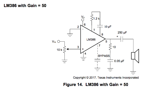
It was extremely noisy. why!?
Some cardinal truth shineth forth from some mucking around on google and allaboutcircuits.com:
All audio power amplifiers have extreme sensitivity to power supply decoupling and ground path hygiene.
if circuit has really high gain (yes) it is very important the outputs dont have absolutely anything to do with the inputs, eg. no long trace runs (guilty).
So had to order the following components from Mauser to keep the integrity of audio amplifiers internal religion:
0.27 mf * 3 - polyester (mylar) film caps 47 pF - ceramic capacitor 10 mF * 2 16 Volts - electrolytic capacitor 470 mF 16V - electrolytic capacitor 0.1 mF * 3 - Polyester (mylar) film capacitor
Might consider 8PIN SOIC to DIP ADAPTER.
back to LM386mx June 2 2021
testing the old all-in-one schematic and why or why not it doesn’t work.
Trying now schematic with LM386 with GAIN = 50.
back to LM386mx June 3 2021 tests
The gain was great but horribly noisey with no music almost. So now we return to the drawing board and figure out the last option with LM 4861 THIS TIME with a high gain circuit.
- tested the 386 board
- ordered capacitors for THT circuits
- currently studying grounding patterns again. If the high gain LM 4861 doesnt give optimal results then the grounding matter will reinvestigated and then be left for later - and i will focus on the other aspects of my project. Dont have the optimal values though. 4.
4 june 2021 replace the caps and solder the LM4861 hi gain boards and DECOUPLING
1.Smart highschool pupils in Romania used to build magnetically-induced earphones using the LM386, a big coil around the neck as inducer, and a tiny magnet inside the ear as the “vibration part”. The LM386 amp hooked to a smart phone was able to induce the sound into the ear using that tiny magnet. Result? Cheat the exams through a phone conversation with somebody else who transmit the correct answers/results for tests. There was no visible wire going into the ear and the sound was pretty damn good. LM386 is cheap and the resulting system is sometimes sold for around 50….100 bucks. And there are a lot of persons who wish for such a device to pass exams without even coming to school. When exams session come, such persons make a lot of money. - lm386 tales
DECOUPLING of LM368 tips:https://www.electro-tech-online.com/threads/best-input-capacitor-values-to-lm386-to-cut-all-interference.154446/
4 june 2021 success!!
The board with LM4861 finally worked - there was no noise and the amplification gain was loud without being harsh and consistent across a range of 8 ohm speakers!
It seems the signal ground and supply grounds that I left unconnected following LM386 amp and general audio best practise - on this circuit with a direct connection, it seemed to work quite well.
The LM4861 does not need an output COUPLING /DC offset filter capacitor as the LM4861 - and for the input I used a THT 3.3 mF capacitor, which I had also used to make a microphone for the Konch chair project.
After this new grounding issues that got solved I tried to understand a bit more indepth about grounding through this brief article.
Star Grounding might be a safe way to connect these currently “seperated” grounds. It means we designate a special terminal as “star ground” - and all other “grounds” will be referred to this one point. In this way every single place that is connected to ground in the entire box would also connect to the star ground point.
However first things first - and the new board will need to replace the dangly and makeshift electrical components that were used for testing in order to head toward the finish line with this part of the project.
The accessories used TO REPLACE the UPDI connectors are thus:
- 2 Position Wire to Board Terminal Block Horizontal with Board 0.138” (3.5mm) Through Hole
- Connector Header Surface Mount 2 position 0.079” (2.00mm) that connects to Input Audio via the JST-PH Cable
- Power Barrel Connector Jack 0.70mm ID (0.028”), 2.35mm OD (0.093”) EIAJ-1 Surface Mount, Right Angle for the 5V power connected via a CONN PWR PLUG 0.7X2.35MM SOLDER jackLED
adjusting loudness
Key design parameters for audio power amplifiers are frequency response, gain, noise, and distortion. These are interdependent; increasing gain often leads to undesirable increases in noise and distortion. For this reason there might be good reason to add a volume knob at the output of the amp rather than controlling gain at the input.
5 june 2021 success!!
Remade the exact same board schematic as above, and instead of shorting input signal and Power ground artifically, as above (which worked in making a crystal clear amp), instead I included it in the schematic - using proper components this time. However, could not hear almost anything during testing.
I soldered a new board and tried again, eliminating the components, switching the speakers and inputs - again nothing!
What a dissapointment from what I thought was finally a near perfect amp.
I decided at this point to move on completely to other aspects of the project.
5 june 2021 starting with making experiments in PCB mounting for my final board - and to use Fusion 360 to make a design for a box.
6 and 7 june
I wanted the ATtiny to have enough I/Os for the use of LED’s as well as use as many of the 16 pins that were on the DFRobomini SD reader, if possible.
At the time I had access to only 5.5 * 7 cm one sided copper boards (I tried to avoid double sided to avoid grounding issues with the audio).
I use CopperCam and 0.1 mm bit to trace my first board which I am still in the process of testing.
Today I am moving forward with Fusion 360 as well.
8 june 2021
Kitija programmer works, mine didn’t in successfully pinging, flashing and programming. HOwever no response from the AtTiny. - chose at tiny minus the Optibooot option. - The issue might v well be the common RX AND TX connection lines between DFrobo and the Attiny.
-
LED lighting up
light up an LED to follow audio voltage level, by using a somple prop ADC - whcih takes the value from the DFROBOmini ADC and translates that to a range of values on a counter to output a PWM or pseudo PWM signal to the LED.
11 june 2021
Making LED mic-audio reactive experiment with code from https://forum.arduino.cc/t/sound-sensitive-microphone-to-led/228142/11
https://clementzheng.info/Joinery
https://www.adafruit.com/product/1131