9. Embedded programming
The assignment for this week was to read a Micro-controller data sheet and program the Hello board to do something, with as many different programming languages and programming environments as possible.
The Microcontroller ATtiny412
The ATtiny412 used for the Hello Board, is a microcontroller using the 8-bit AVR® processor with hardware multiplier, running at up to 20MHz and 4KB Flash, 256B SRAM and 128 bytes of EEPROM in a 8-pin package.
The new ATtiny chips are a new matrix of devices - and they have varying features.
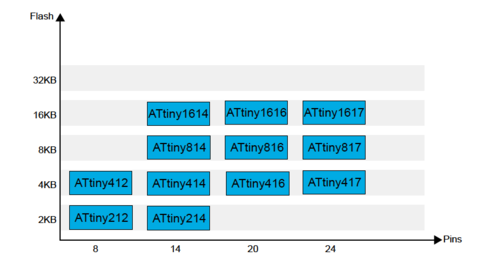
The features are encoded in the name itself.
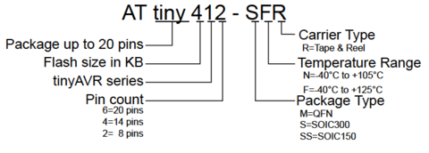
However their real capabilities and differences are only understood by thoroughly going through the datasheet - which is huge. I downloaded the datasheet from Digikey - and went through some of the basics of the ATTINY 412.
After cross referencing others material, I found nice comparison between an oft confused term - microcontrollers vs microprocessors microcontroller vs microprocessor There can be many comparisons between a PC and a microcontroller - except in the area of multitasking which a computer memory is capable of. However a microcontroller is focused on single task - but also has “many thousands (or millions!) of logic gate circuits and memory.
As it says in the former link, on big question is “Why would it make sense to use a microcontroller to perform a logic function that a small fraction of its constituent gates could accomplish directly? In other words, why would anyone bother to program a microcontroller to perform a digital function when they could build the logic network they needed out of fewer gate circuits?”
Apparently, the answer is quite complex but averaged out as “Ease of configuration and Flexibility”. eg. A single button press can be used to display the time of the day, the no. of times its pressed, light an led, or read the duration.
Likewise, an Arduino is designed for quick prototyping as well as generous amounts of inputs, Outputs and Flash Memory - to see what works and what doesn’t. However the size and dependence on an external computer certainly does not make it a super downscaled “embedded device” to be used in practical contexts such as a mobile phone. It also allows you to take a prototype hobby project “all the way”.
Studying the ATtiny412 datasheet
Going over this SparkFun tutorialwas helpful as it advised on how to approach reading a datasheet. One has to admit that this is an overwhelming exercise as its very difficult to get context of the the technical details and vocabulary - difficult to imagine the context of their use from the descriptions and diagrams alone. It did help me to go through some of the other colleague’s thoughts on this digital bible to get some focus areas.
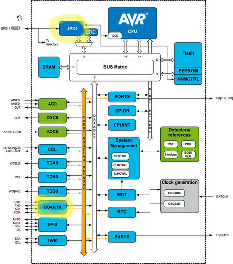
The four basic blocks of a microcontroller can be broken down as a CPU, Memory, System Clock and Peripherals.
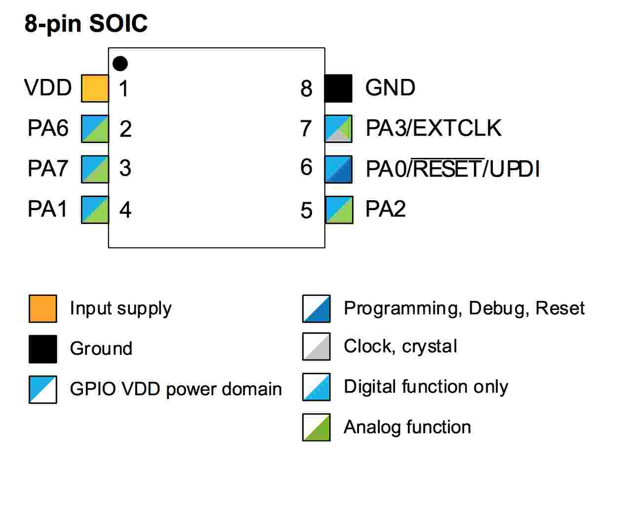 ATtiny412 PINS that divide 4 basic blocks
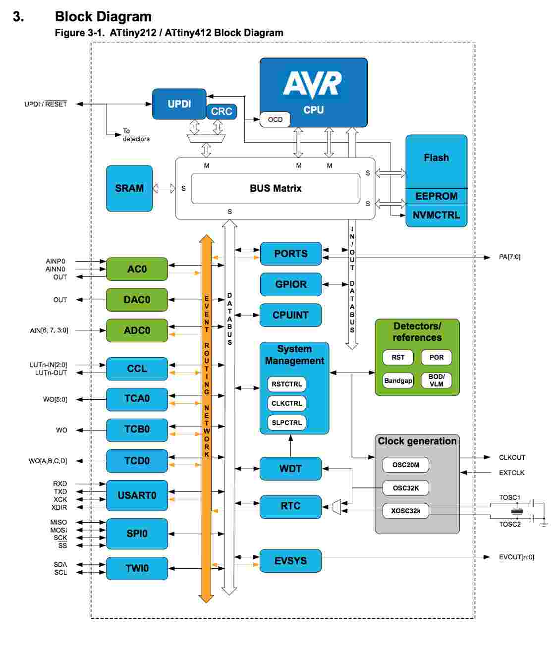 ATtiny212/412 block diagram
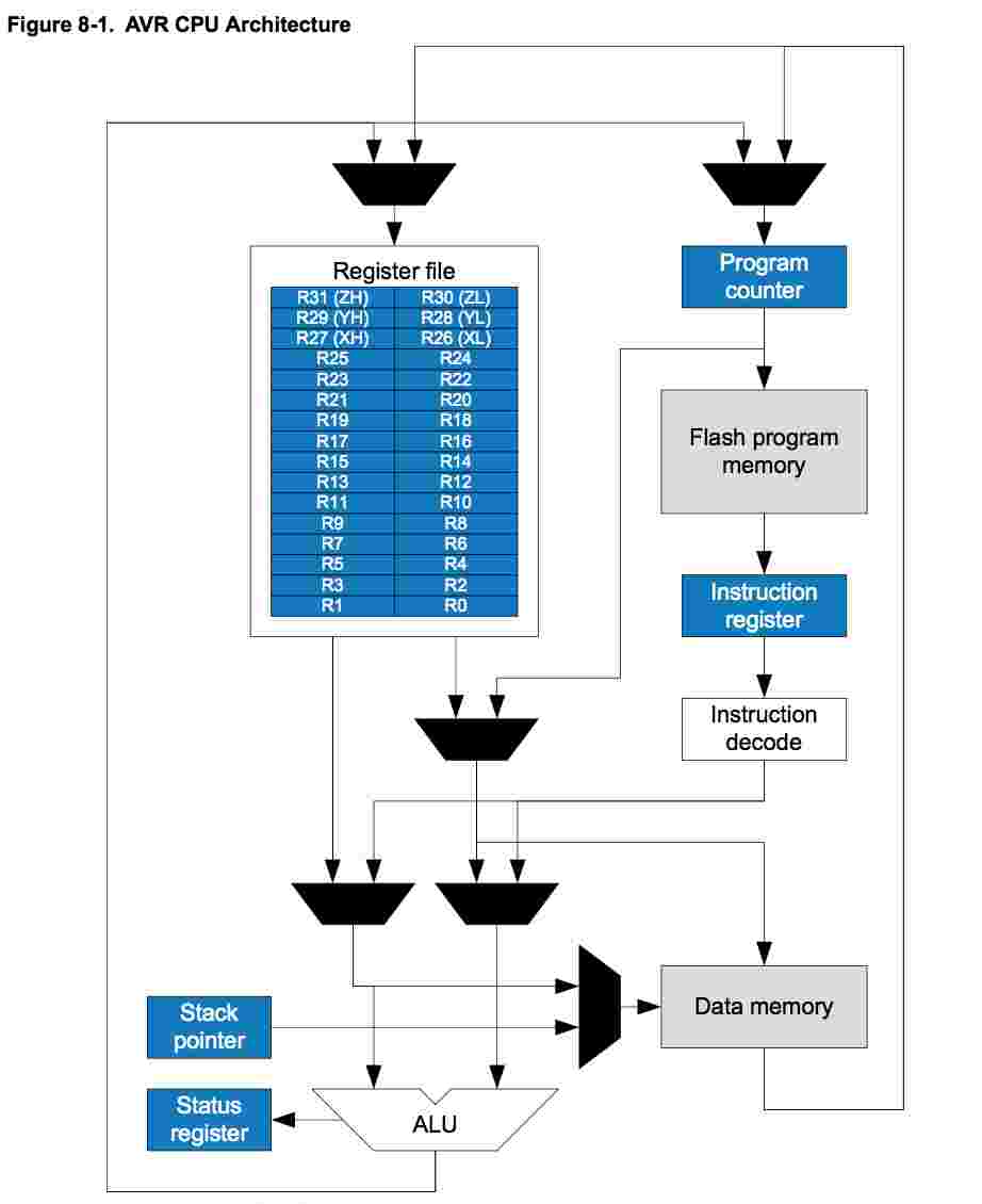 ATtiny412 CPU & memory flow
 microcontroller behaviour range with various sensors
There were also other online resources giving a more contextual overview for complete beginners.
I referred to this Medium Blog, an ATTINY overview blog and an article that talks about the AtTiny’s unique USART (S for synchronous)USART as opposed to UART (Universal Asynchronous Receiver Transmitter) in a process known as bit banging.
The core features that differentiate it in general are:
A 2/4KB Flash memory, with 128/256bytes of SRAM and 64/128bytes of EEPROM in a 8- pin package
Ideally the programming and instructions for the task are sent through the right pin to the right place at right time - It is to understand this instruction vocabulary that we make use of “[data sheets]”. For instance, LED_AVR PIN3_bm was identified as the port for asynchronous signalling of the LED.
Hello Board
There is more than one way to program the ATTiny 412. One option is to use the Arduino hardware & breadboard (eg. the Arduino Nano) as a jtag2updi programmer on a breadboard. The other one that I used is to use the Arduino IDE software - and copy the programme to the Hello Board through a host board.
The ATTiny 412 Hello Board, with a UDPI programmer, a USB-FTDI host board with 5 V power, and long USB cable were initially provided by the lab for pickup because of the virus pandemic. As a result, once I was able to mill my own HelloBoard, I was able to have 2 boards to check my code! A backup that is great just in case you suspect if the issue is with your board, code or just your hazy head.
 Attiny412 hello blink board with led
Setting up UPDI Programming Toolkit with Arduino, megaTinyCore and pyupdi


As seen on the image above, the HelloBoard loaned from the Lab seem to be detected by the terminal window. While the board seemed to work initially, the hello board has been flashing red which I initially thought might indicate some issue with the circuit load (After consulting with the FabLab master, the Red flashing light was just a red LED and not signifying anything wrong with the signal.)

The UPDI programmer chip acts as a communicator between the AtTiny Hello Board and the computer’s Arduino IDE. (IDE = Integrated Development Environment)
In this setup the Hello Board with the ATTINY 412 chip is interfaced with the USB host via an FTDI slot -> this goes into one end of the USB.
The host board with the UPDI slot, is connected to the ATTINY412 via a connector pin is connected “at other end” of the computer through a 5V USB cable.

Arduino IDE setup
ARDUINO installation ran into slight problems when the build folder somehow failed to show contents, that are needed to program the hello board. This was solved after much anguish - it so happens that earlier when I was practising Terminal commands for github, I accidentally had deleted my entire Documents folder with the -rm command! The backup on iCloud saved me, and I have used the Documents folder directly from the iCloud since then. As a result, the Build folder installs itself in the Documents folder during installation, however during execution it is unable to find the path to build the files locally. Not many have their files up in the clouds, so it’s not likely to affect most - but a good point to remember. I manually created a Build folder in home directory, and all was good.
Once this was fixed, source for SpenceKonde’s Arduino core installation for the new megaAVR ATtiny series chips was copied.
This was added to the additional board manager URLs 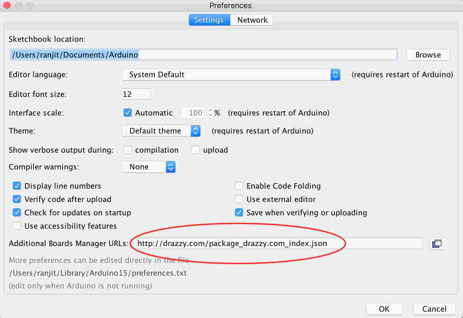
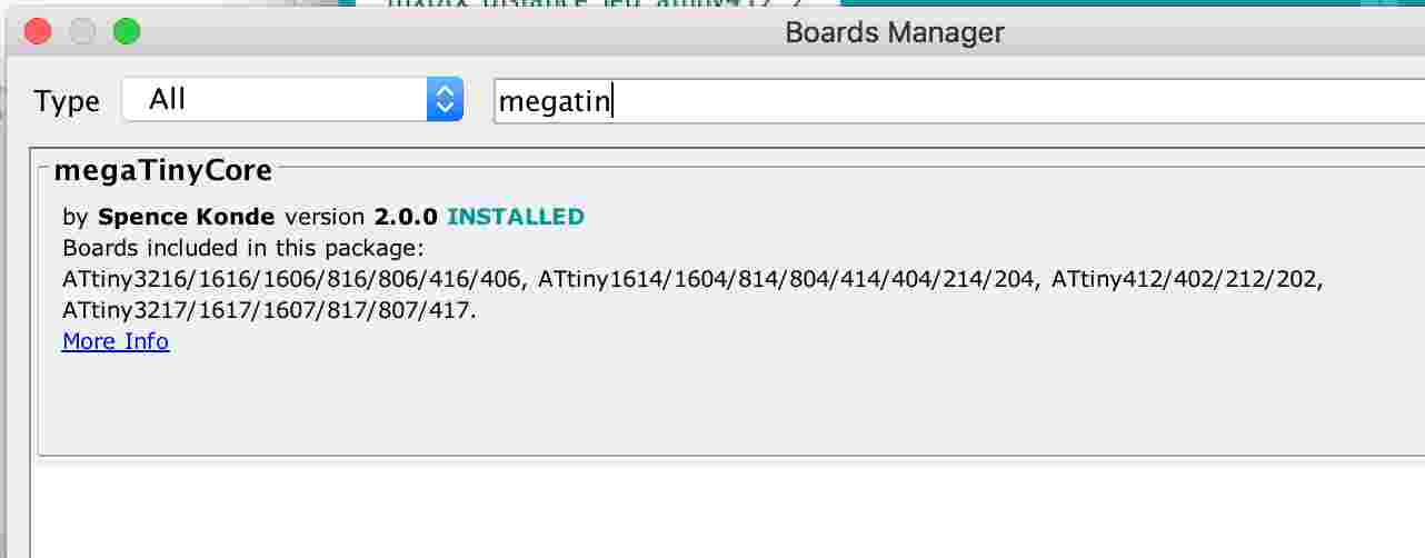
To be able to compile the code, first install the megaTinyCore library using the Libraries manager into the Arduino IDE and select the ATtiny412 board.
Within the preferences text, one need to include the path of the new Build folder where our .hex files reside after export from ARDUINO. (Arduino needs to be shutdown while this is saved).

So, one needs to compile the code with the Arduino IDE and then send it to our board with pyupdi.
Pyupdi was executed via terminal after PYUPDI download with the command cd home_directory/pyupdi ./pyupdi.py
Meanwhile, the Arduino programme was executed with a simple LED delay code - once it was saved, a “.hex” gets stored in the build folder.
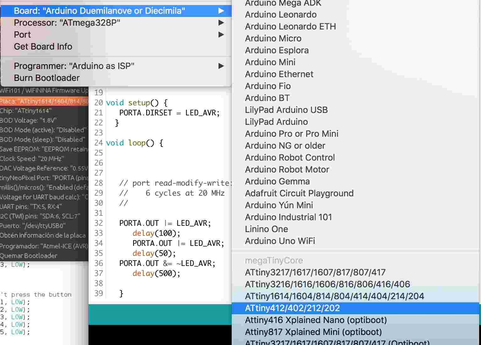
Before exporting the file for build, ensure the right settings and board are selected:
Then run pyupdi with the name of the board you’re working on tiny412, the port where you want to send the code and the code itself eg. ‘Blink.ino.hex.’
The blink programme on the Hello Board was tested with an uploaded version with minor changes in the blink programme LED delay.
#include <avr/io.h>
//This header file includes the apropriate IO definitions for the ATtiny412 microcontroller device

#define LED_AVR PIN3_bm
//

void setup() {
   PORTA.DIRSET = LED_AVR;
  }

void loop() {


   // port read-modify-write: 304 ns/bit
   //    6 cycles at 20 MHz
   //

   PORTA.OUT |= LED_AVR;
      delay(100);
      PORTA.OUT |= LED_AVR;
      delay(200);
   PORTA.OUT &= ~LED_AVR;
      delay(500);

   }
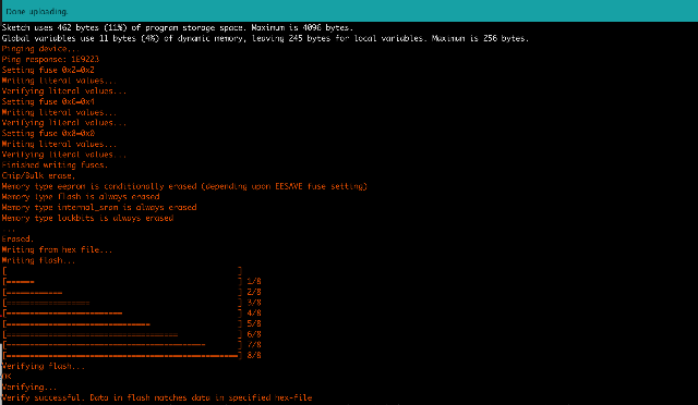
This is the file that needs to be programmed from the host board to the FTDI based ATTINY412 and a USB-FTDI convertor. Once your program is correctly compiled, open a terminal to send the .hex file to your device.The host board and the FTDI-USB interface are found through the command ls /dev/tty.*
to know the name of your port.
It should look like >> 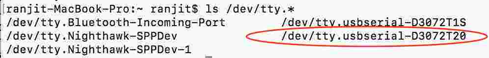
Once the ID of the programming board is identified as marked in red above, the command for programming on terminal was:
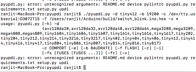
*./pyupdi.py -d tiny412 -b 19200 -c /dev/tty.usbserial-D3072T1S -f /Users/ranjit/Arduino/build/412blinkt.ino.hex -v *
Once the chip is programmed, the LED successfully blinks as per the Arduino programme!
Hello Board led blink from Ranjit Menon on Vimeo.
Arduino BLink Test with basic switch
A March 2021 update based on the upgraded version of the MegaTinyCore by Spence Kone on GitHub.
After this exercise I try then to test with the Arduino blinking along with the triggering of the switch.
At first I tried to run it from the terminal window using the older pyupdi library abd the .hex file.
The programming, while detecting both boards, ran into some errors.
On the Arduino IDE however, I was able to successfully run it directly with the new upgraded MegaTinyCore and Arduino - it sent the compiled code directly to the ATtiny 412 Hello Board.
the blink to a switch code
include 
define LED_AVR PIN3_bm
define LED_AVR PIN7_bm
include 
include 
uint8_t counter;
void loop() {
//check to see if PA7 is pulled low if(~PORTA.IN & PIN7_bm){ //wait until PA7 returns high while(~PORTA.IN & PIN7_bm){ _delay_ms(5); counter++; if(counter >= 5){ //set PA6 to LOW //PORTA.OUT |= PIN3_bm; _delay_ms(100); //set PA6 to HIGH PORTA.OUT &= ~PIN3_bm; } } } }
Upon uploading to the board, the LED was supposed to be blinking on and off with every switch trigger - however, it ended up switching off completely. This is something I am trying to figure out.