week 6. 3D Scanning and printing
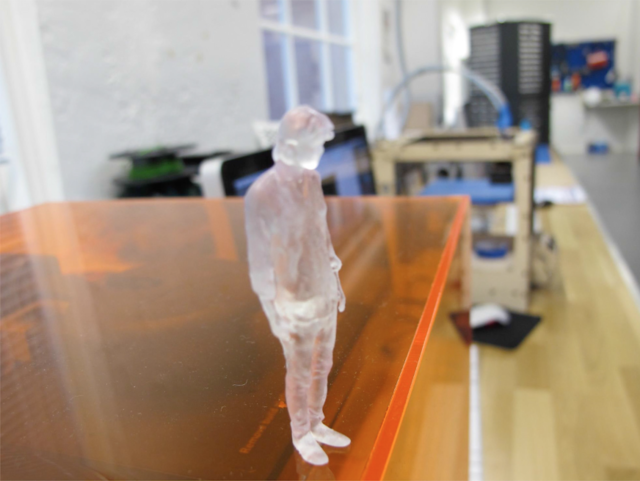
Scan & SLA print of myself with an ipad in 2015
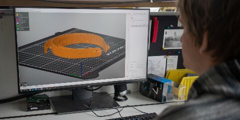
Slicer-Programm, Photo: Ars Electronica / Robert Bauernhansl
“I’ve heard that you’re currently finishing face shields on the 3D printer – a good idea in the current situation. What do you need to get a finished face shield? What exactly does it consist of, what steps are necessary for the production?”
Thomas Schwarz: “The most important thing is of course the 3D printers, of which we have five copies available that are ready for use. For the face protection we use a laminating film here, which is cut by a laser cutter here, but it could also be cut with scissors. We print with PET-filament, which has good hygienic properties. The whole thing consists of a laminated sign, which is cut out by the laser printer, and a head holder, which is produced by the 3D printer. There are two different versions for the face shields, one slightly larger and one smaller. It should also be mentioned that this is the Protective Faceshield from the Prusa company, who came up with it. Our 3D printers also come from this Czech research company.”
— Ars Electronica Blog | Apr 8, 2020 | by Katia Kreuzhuber, The Museum Never Sleeps
This interview conducted in 2020 during the Peak of the first wave of Covid; shows the adaptive power of digital fabrication, in this case a 3D printer for face shield manufacturing during the sudden Covid surge.
In order to better understand the history and contemporary state of 3D printing, I referred to multiple sources.
The books :
3 printing by John Jordan and The 3d printing handbook from 3D hubs and some additional Online materials: from 3D hubs and Core 77 design blog*
An initial question: What is the process behind 3D printing?
“the process of additively building up a part one layer at a time. There are a range of 3D printing technologies with each having their own benefits and limitations and each being able to print parts from different materials.”
---- Excerpt From: Redwood, Ben. “The 3D Printing Handbook.” iBooks.
3D printing basically uses additive manufacturing methods (successive addition of materials layer by layer). The main idea behind 3d printing is Additive manufacturing as opposed to Subtractive manufacturing.
Subtractive Manufacturing begins with a block of solid material - CNC milling, turning (lathe) and machine operations like drilling and cutting are all examples of subtractive techniques.
Another important distinction to understand about 3D printing in the fabrication ecosystem is to differentiate it from other processes. Hence, 3D Printing is an additive method while CNC milling is subtractive.
Subtractive manufacturing is capable of producing highly accurate parts with excellent surface finish. Almost every material is able to be machined in some way and is considered the most cost effective method of production.
However where Additive Manufacturing excels is in the fact that Parts can be produced in almost any geometry, does not rely on expensive tooling. The unique advantages in the production pipeline thus include rapid verification and development of prototypes and low-volume production parts.
One of the main challenges in 3D printing is to navigate through vast number of technologies and materials in order to determine a best fit solution. The most commonly used material is something similar to plastic - not the most environmentally friendly, ie Polymers. Polymers for 3D Printing are generally divided into 2 categories: Thermoplastics and Thermosets.
For the Line Test exercise, I use Thermoplastic. And for the CAD designed 3D printing job I use Thermoset.
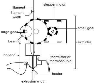
The process for thermoplastic, is known as “Fused filament fabrication (FFF)”
These filament-based 3D printers (also known as FDM or FFF 3D printers) have a spool of filament fed through the extrusion head - and once the nozzle reaches the desired temperature, a motor drives the filament through the nozzle - while the extrusion head moves around cooling and solidifying the model.
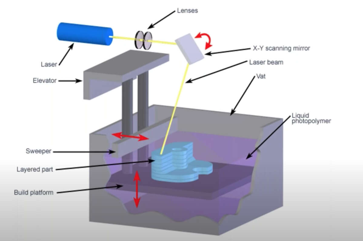
This is different from SLA printing on the other hand, where an object is created by selectively curing a polymer resin layer-by-layer using an ultraviolet (UV) laser beam. The materials used in SLA are photosensitive thermoset polymers that come in a liquid form.
source: total3dprinting.org
An overview of an FFF style printer:
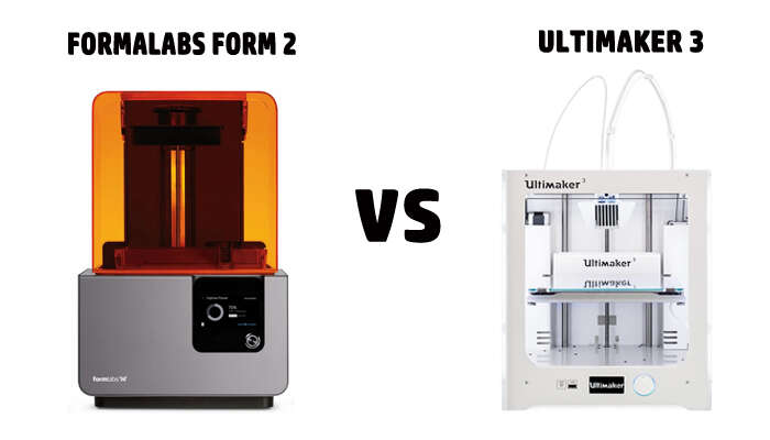
Ultimaker is a filament based printer, with a fused filament fabrication (FFF) process as compared to FORMLABS form 3; which uses the SLA (stereolithography apparatus) process for 3d printing.
Ultimaker 3 uses an FDM or fused deposition modeling (a proprietary term for Fused Filament Fabrication) is a 3d printing process that uses a continuous filament of a thermoplastic material. In other words, the raw plastic material is heated up and extruded on layers to create an object.The speed of the printing head, operating horizontally mainly and adjusting in bits vertically, can be adjusted to suit the complexity of the model. It is the one of the most popular models for 3D printing out there.
source: wikipedia / Fused Filament Fabrication
The Ultimaker 3 features a 8.5 x 8.5 x 8 Inch (215 x 215 x 200 mm) build platform, with a layer resolution of 200 to 20 micron (0.2 to 0.02 mm). At 50 dBA it occupies a decibel range shared by Fax Machines. It supports a range of materials such as PLA, ABS, CPE, CPE+, PC, Nylon, TPU 95A. Typically, the Cura software is used to edit the job before sending to the printer. The finished work can be taken off the machine.
An overview of an SLA style printer:
FormLab Form 3 - The Formlabs has a completely different process known as SLA (stereolithography apparatus/optical fabrication/resin printing) - which basically means that there is a liquid resin that gets heated up with a very powerful laser to make solid layers.
An SLA printer such as the Formlab produces very detailed prints and some of the most accurate 3D printed parts, as the light source can solidify material very accurately. With this process, features can be produced that have dimensions down to 0.2 mm and walls with a thickness of 0.5 mm (sometimes even smaller). In this way one can 3d print parts that resemble injection molded ones. However the printer itself is very expensive (such as the Form 3 from FormLabs costing over $3500!)
source: https://formlabs.com
source: https://formlabs.com
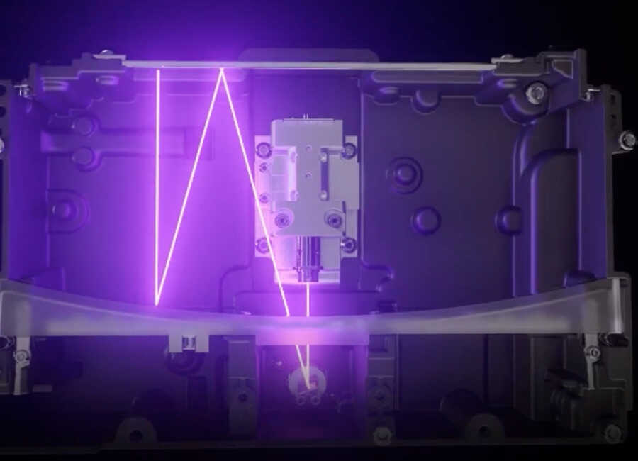
Form 3 model using a custom-designed Light Processing Unit (LPU) - a compact system of lenses and mirrors to deliver accurate, repeatable prints.
The Form 3 can be used to produce highly precise parts and can handle quite irregular shapes. The form 3 photopolymers however need to go through an extra bit of process to be washed and left under UV light to be able to washed, cured and dried.
Group Assignment - design rules
The group assignment was to test the design rules of the 3D printer.
There are many parameters one can control on 3d printer. Out of this, Build speed, Extrusion Speed and Nozzle Temperature control are set by the operator (some machines use presets to set these up such as Preform for Formlabs).
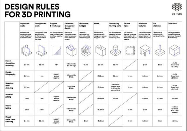
source: [3DHubs.com]
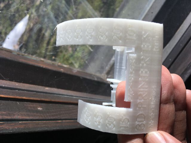
In addition I used a file from thingiverse that included tests for overhangs, bridges, stringing, extrusion, temperature, belt tension - and had the following result from the Ultimaker 3.
Some useful terms for 3D printing design rules:
Overhangs: Knowing when a model will need to print supports is essential,and with this test one can know what angles are printable and what are probably not.
Bridging: The ability to print two pillars with no supports.
Stringing: Testing retraction settings ie seperate features testing on same layer
Temperature Tower: The temperature controls the consistency of the prints
Belt Tension: Not sure how this is visible in the print itself specifically, as it refers to the physical belts on the printer being tightened to necessary level.
Here are the test results from the Ultimaker Cura.
3D PRINTING using the FormLab SLA
For the 3D printing session, I was wanting to create a “sacred object” - in this case a ShivLing, which is an ancient Indian symbol depicting the union of the divine masculine and feminine aspects of the universe.
In the snow-capped Himalayan mountain ranges, there are holy places for Shiva worship, where Shivlings have naturally formed as an icicle “formation” from water droplets falling into the caves - such a formation reminds one of nature’s naturally occuring additive process.

source: wikipedia
I used Blender to import a suitable model from Thingiverse - and converted it to an STL, to test how the Formlab’s high resolution print might turn out - as a first 3d printing exercise.
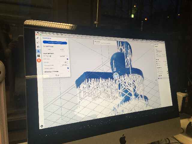
In the FormLab software Preform, the material chosen was white resin with the version number - where I chose 50 microns resolution for a fine print. The size and orientation were recommended for top down printing - hence the model was pre-adjusted to a slight angle. Before starting the print the interface allows adjustment of printability and other metadata such as volume of material used as well as the time taken to print.
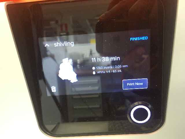
The FormLab Form 3 has an interface that displays the model as well as the time taken for print and a depiction of the process parameters and percentage of completion.
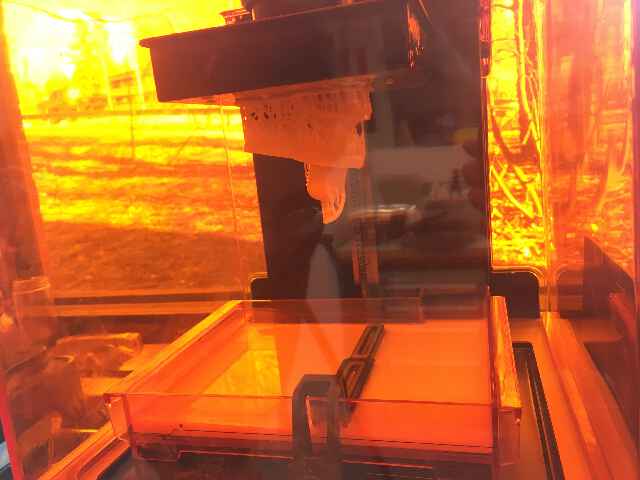
An optical engine made of high powered lasers and mirrors finished the job in over 11 hours. It results in this inverted build process of SLA printing results in an “upside down” model. So what you “see” is more or less what you get with the FormLab at least in terms of resolution.
The FormLab printer needs a bit of post processing. One needs to transfer the finished print to a bath with cleaner fluid / IPA. This takes off the finer layer of uncured resin stuck to the model.
One needs to handle the entire post production process with gloves & safety glasses.
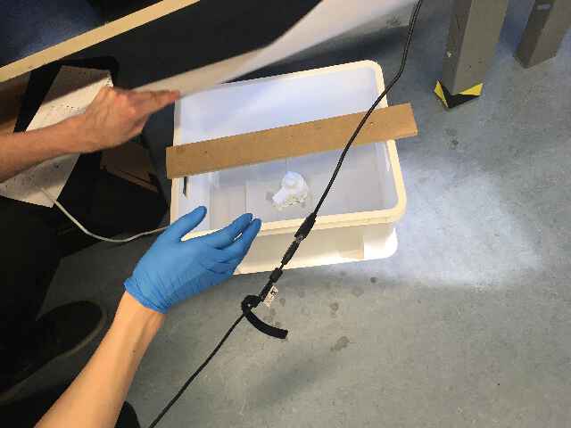
Apparently the SLA printers also sell “curing stations” as an add-on. In our case, we used a DIY curing chamber with UV light places inside a box. Apparently Sunlight also works, if it is left out long enough with the best and natural source of UV.
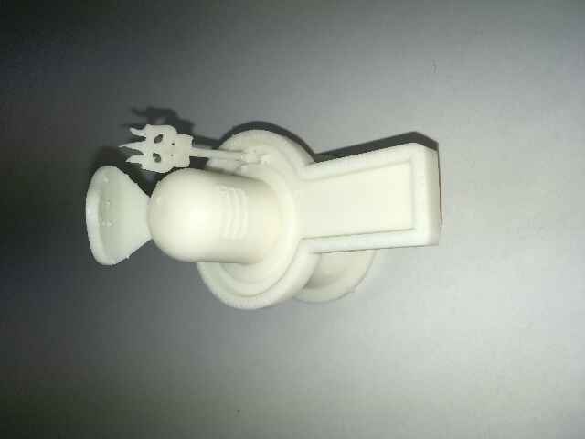
Since the shape was intricate, the supports were highly congested. I tried to initially break off the supports by bare hand - however I had to use a flush cutter - this resulting in accidentally snapping off one critical part of the design, the third pronged spear. There were also a lot of small nubs left on the surface, much of which had to be sanded out.
3D PRINTING EXERCISE - modeling on FUSION 360 and printing with SLA Formlab
Parametric design using Fusion 360
The previous 3d design was based on a file from the internet - and for this one I wanted to create something with SLA Formlab.
My final project in the form of mantra box would need to have self contained units within: with possible hinges or lock-in features for battery compartments and so on. Hinges are also things that break easily. Initially, I chose a basic hinge design and print experiment with Wallthickness, clearances, & using the parameter definitions in Fusion 360 in order to pre-test and print a 3d printed hinge.
I used a reference tutorial from the Product Design Online crew - in order to test the hinge design. However, I was slightly lost with some of the features in Fusion where I was getting stuck - and due to time constrains I moved onto something slightly more simpler yet additive with room for modifications.
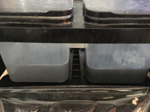
I decided to create something bottom-up, well-rounded yet simple and focus on the outcome more. I decided to go with design of a simple cellphone holder, that would look like an “off the sheld” product with the help of the SLA printer.
Making the simple cellphone holder - is based on a tutorial that I found online for the Fusion 360. The tiny modification I made was to add Thin Lizzy logo onto it.
Steps on Fusion 360
1. sketching the basic form & Offsetting
First idea is to use the line tool to create the basic shape, with a front side view
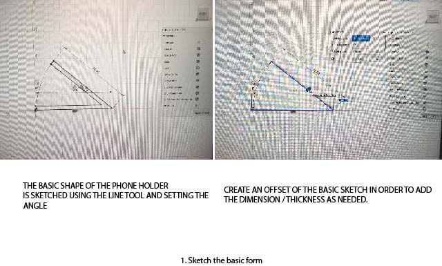
First I choose O for offset of 40mm, and choose a ‘2 point’circle tool C for the rounded edges.
2. Trimming & Shaping the form
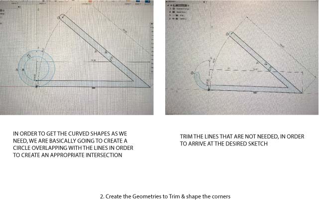
One proceeds to create the circles needed in order to add the necessary curves to the sketch. The remaining ones are deleted using the Trim function.
3. Extrusion & Fillet
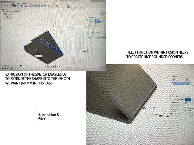
Finally, we need to extrude this shape into a 3d model, hence we hit the “E” extrude function that automatically changes the view into an isometric one.
We give it an extrusion of 60 mm, and we have the 3d model of the extruded sketch.
However, the edges are still quite sharp. In order to bevel and round them. This time instead of creating a 2 point circle and then Trimming the parts we do not need, we simply choose the simple “Fillet” tool from the modify category - and curve the edges at the front side bottom.
I am really happy with this outcome so far. I am tempted to add a slight modification i the form of the logo of one of my favourite bands of all time - Thin Lizzy!
4. Adding the Thin Lizzy logo
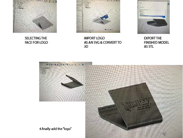
The logo is found online in SVG format. Once imported, it was slightly difficult to orient the logo by moving it around. The moving function works slightly different because of the dimensional rules in Fusion.
I was eventually able to create a mild 3d extrusion (shotcut ‘Q’) on top of the front cafe of the phone holder
5. Taking the print to the FormLab printer.
The FORM 3 model printer was used along with Preform software that comes with it. After setting up the FORM 3 resin tank (the first thing to do was to check the build platform if it is clean as such), I used the Preform software in the computer connected to the printer, in order to setup the print work. Here I open the STL file and then initially adjusted the object with supports.
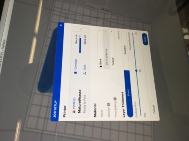
The Preform interface allows me to make some changes if needed in minimal steps:
- PreForm’s automatic algorithms set up the print’s layout, orientation, and supports. On the right side of the interface, one can check the Resin type (‘Black V4’ in my case).
- Layer Thickness is set at 0.05 mm
- The estimated print time is mentioned, which is at 9H 30 min approximate.
- The number of layers needed and volume of resin is mentioned.
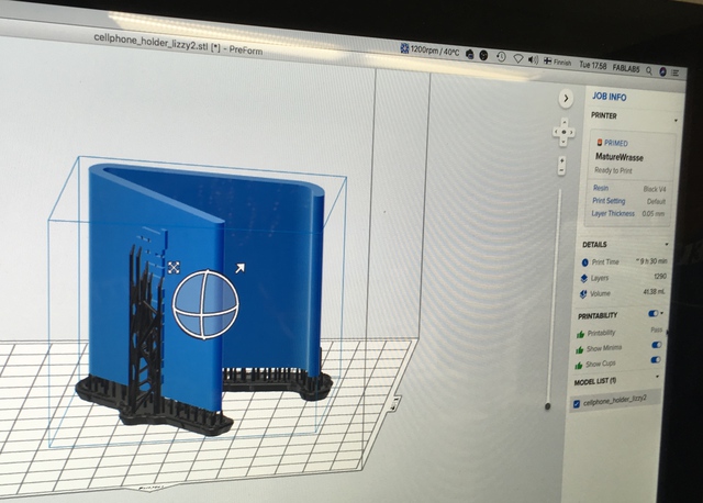
The layer thickness, support density, and other parameters can be adjusted. However for me, I only needed to re-orient the Job in the software so that I could get the supports on the base of the object that would make it easier to remove. Especially because some of the supports were branching into the “logo” so I clicked the magic wand on the interface that automatically shifted it into a better position where that face was less exposed to supports.
Further adjustments can be made prior to confirming the primed print job
Once sent, it opens up on the Form3 interface - and displays clear information in a sentence structure - it is quite user friendly. The time taken for the print and even a simulation of the print file is on display.

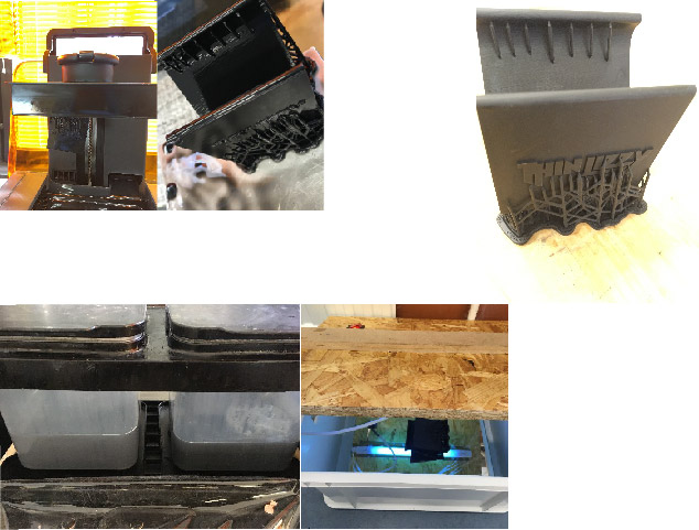
6. Post formlab Printing & curing
After the printing, the job was carefully scooped out of the printer with a thin chisel. In order to clear out the black resin isopropyl alcohol was used.
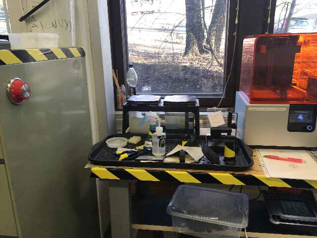
Once the job was extracted it was then dissolved in the two rinse buckets for 10 minutes each (set with a timer). The rinse bucket has a FormWash liquid that are partially filled. The workspace in this section is to be operated with gloves and masks as the resin and solvent can be toxic. There is also a trash to dispatch only Formlab waste.
A number of tools are in use in this post cure section. These include tweezers (to remove supports carefully), scrapers (to remove parts from build platform), flush cutters, isopropanol, gloves etc.
Once removed from there, it was kept in a UV box for Post-curing (it enables parts to reach the highest possible strength and become more stable.)
According to formlabs, many methods for post-curing exist, from curing simply with light (natural sunlight, UV nail salons, UV curing stations, DIY UV cure boxes, etc.) to using both light and heat. Heat accelerates the process and enables even more complete bond formation, resulting in increases in material properties impossible to achieve with light alone.
For small prints, a low-cost UV nail salon might be an effective post-curing tool - and this is where I cured my final design.
- post processing: post-curing, isopropanol and UV lightbox
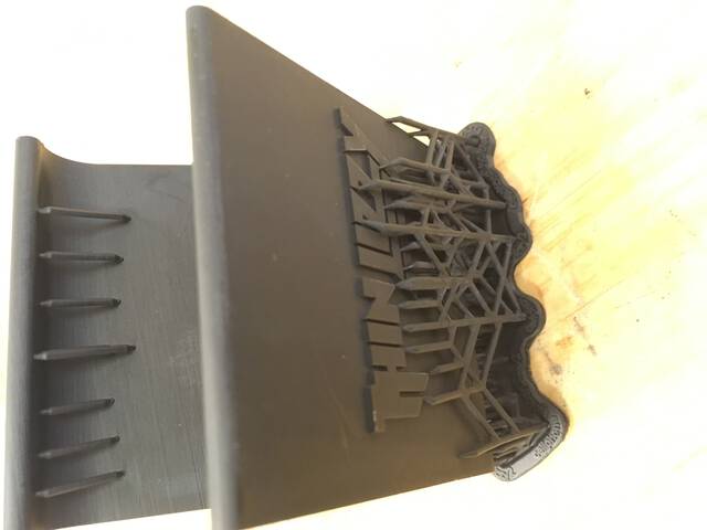
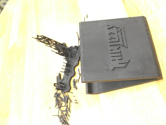
6. Clearing the Supports
============
3D SCANNING EXERCISE
The exercise here was to use basic 3D scanning with Artec Eva and Asus Xtion. I used the Artec Studio 15 professional software with Artec Eva and Skanect software with Asus Xtion.
For the class exercise, and for the subsequent scanning - it was recommended to use a human size figure in order to try the scans.
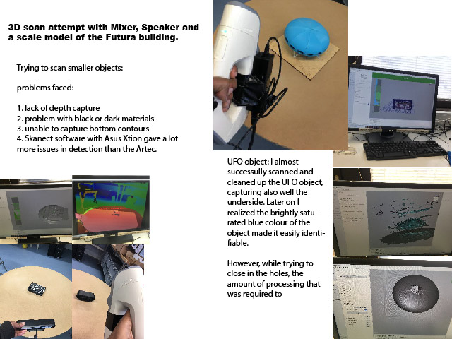
However I was very curious in scanning smaller objects, especially to the size of smaller industrial components.
For the scanning exercise I experimented with various objects - that were within the 20 * 20 cm dimension.
3D scanning
For scanning I am using two modules - Artec Studio software with Artec Eva and Skanect software with Asus Xtion.
Artec Eva scanner is a Fast light 3D scanner for quickly capturing precise measurements in high resolution. It is designed to be hand-held and manuevered rapidly around medium sized objects. It works well in detecting human features and outlines, however in my experience, it is difficult to get detais of industrial objects - especially ones with a tight and uncontrasted form.
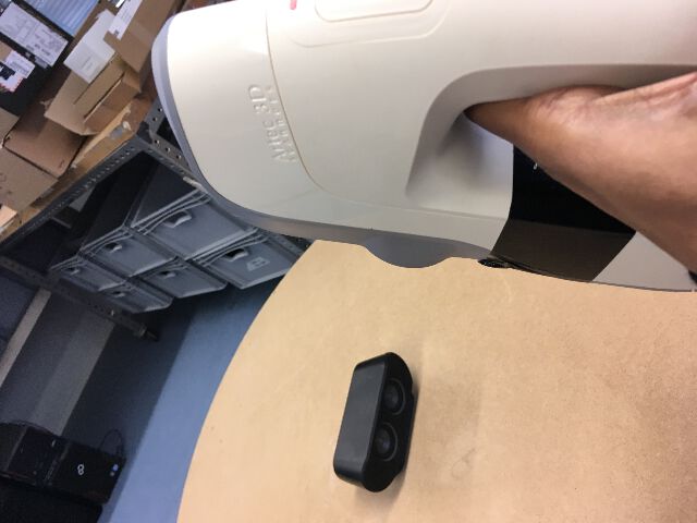
The Arctec Eva 3D Scanner hardware
Artec Eva works with the Arctec Studio 15 software at the lab. The Studio 15 has automatic features to recognize the shape and size of the object to be scanned - and can work with datasets of even up to 500 million polygons, according to their site.
The Arctec Studio 15 software with the Arctec Eva hardware
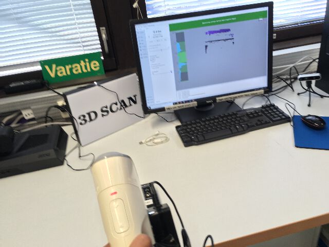
The second scanning combo, uses the Skanect software used in the lab with Asus Xtion Pro is slightly different. The software seems independent from the hardware, and it can capture a full colour 3D model of an object, person, or even a room in order to create 3D meshes out of real scenes in minutes.
On the Skanect, one can pre-cuztomize the scanning artefact depending if it were a scene (body/object/room/half room), bounding box, aspect ratio or as a path.
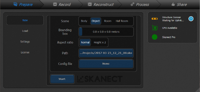
Skanect interface - pre-selection / 3dscanexpert.com
The Asus Xtion Pro hardware uses infrared sensor and adaptive depth to detect realtime gestures and motion - it has low power consumption and seems to be adaptive enough for a range of applications - however at a mere 245 USD , it seems to be not very specialized for scanning if one compares to the near 14,000 USD Arctec Eva scanner.
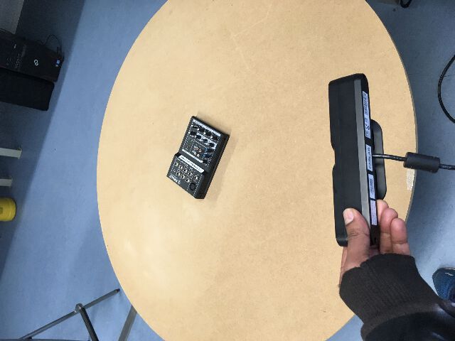
The Action Pro scanner attempting to scan a mixer
1. Scanning with Artec studio 15 with Artec Eva
For my first scan attempt, the Artec studio 15 software with the Eva scanner was used. The preview and record can be controlled from the scanner itself. I am not selecting the texture as such so just selecting the geometry.
Some of the checklists to fulfill with the Artec software were -
Initially one needs to start scanning by pressing the scan button - the green indicator on scanned scanner means it is ready. One can activate the preview mode by pressing “play” on the scanner. The texture and geomtery were turned off in order to just receive the 3D printer information. The sensor needs to be aimed at the object in a way that makes the “ground plane” on which it is resting visible.
- The realtime fusion checkbox needs to be activated - it gives a much cleaner scan.
- There is a meter that shows up with a blue grid that shows the resolution of the scan.
- The frames per second, would matter in how accurately the signals track the object against the noise. However it may also restrict any shakes of the scanner - and have to held more steady.
- A pair of hands is better in this case - however for this experiment I am by my own so its a bit of trial and error in documenting.
- Setup should be ideally on a spinnable table, such that the scanner can remain steady in one hand and another can spin the table. It is also possible to scan manually around the object, however it is a bit more difficult to scan the object this way without significant amount of noise and artefacts.
As my first experiment, I tried to scan a mixer - and results were really squashed against two different surfaces. First the mixer went around and scanner remained steady and second one the scanner was moved around the mixer. Both were did not give the results as expected.
I moved on to a speaker unit, a “UFO” object and couple of other random objects and kept having an issue with being able to capture the object fully on the underside as well.
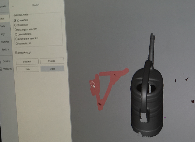
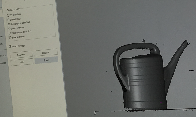
Once the object is scanned it is usually necessary to erase things one doesnt not need in the real-time fusion object. One needs to almost always choose the “retangular selection” tool and enable orthogonal view to delete unnecessary things - (ctrl + drag operation w/ mouse).
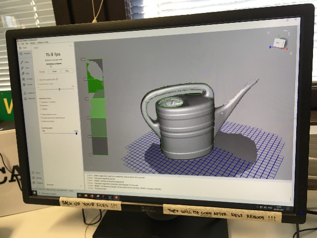
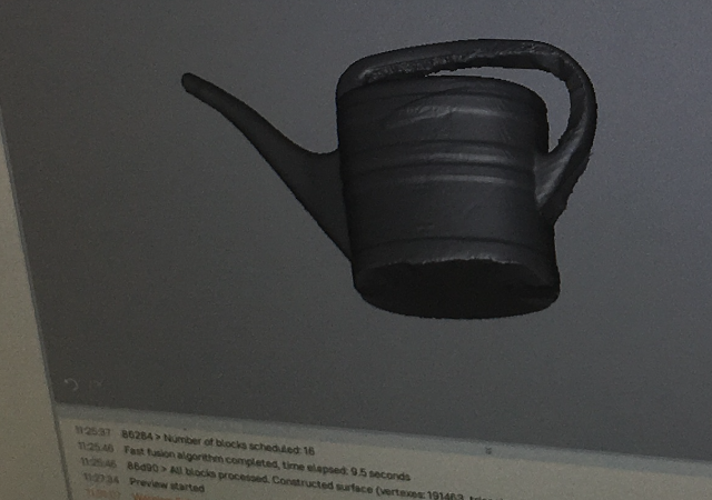
There was a measure of success in “borrowing” an ideal object scanned by 2 others who were scanning the watering bucket - the colour, size and texture seemed to have worked well for the ARTEC to be able to recognize it well.
Here one can see the breakdown more clearly of the steps.
Scanning with the "geometry" selection chosen
Deletion of unwanted artefacts using "2d" selection
Deletion of unwanted artefacts using "rectangular" selection
after Fixing holes and mesh simplification
2. Scanning a complex object using Skanect software with Asus Xtion scanner
Eventually I tried to scan in a guitar tremolo arm module holder part from a 1980s American manufacturer called Kahler.
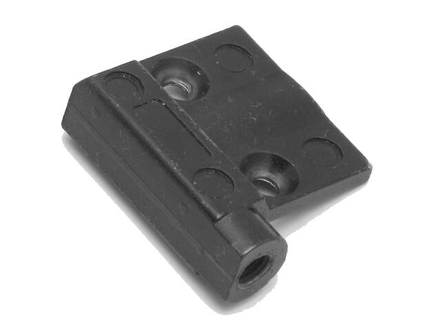
I essentially have a part for the left handed guitar and wanted to create a piece that would be a mirror image, ie for a right handed one. As the manufacturer is from the 1980s, the costs are high and the shipping charges as well. I thought it would be great to experiment and see if I could capture a scan - that would then help in augmenting it with a proper fusion 360 modelled version I could then try to make.
Problem is how to scan it? This is even tinier than the previous ones I failed at.
One of the Fab Lab students however suggested a brilliant idea of marking the surface of the object with some coloured tape - in this way fool the computer vision into identifying the parts. This was to be done with 1. coloured tape, 2. foreign coloured objects around it to contrast it with.
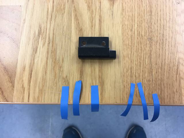

It “almost” worked in the sense that the other objects and the coloured tape designed to “fool” the software into recognizing the object almost worked! however..
the only reason it didn’t work was the black metal part - which was making it “invisible” even though the contours were detected.
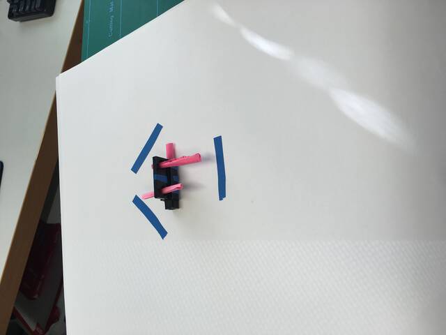
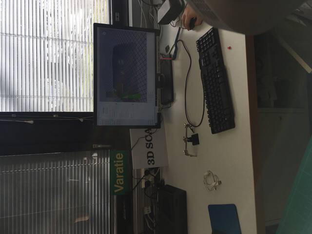
Tried to create a different “coloured base” to check if it worked, but the issue was the same - the “black metal” did not reflect enough saturated light for detection - and as we can see with previous examples, is a problem with a lot of these industrial “black and grey” objects apart from the size.
A future idea would be to try again! This time maybe, spray paint this piece in a brighter colour like yellow to make it identifiable + all the props as mentioned before.
Conclusions
Both the FormLabs and Ultimaker are able to print the same .stl or .obj files. The Ultimaker can use any slicing software however the FormLab required the included software suite. The Ultimaker has advantage of sourcing cheap materials and faster prints and can also use multiple materials together. While both use traditional technique of additive synthesis, the FormLab uses a SLA the resin materials is hardened with powerful lasers giving an extreme high resolution outcome for a 3d printer.
Files to be downloaded
cellphone holder: