5. Electronics production
This week the assignment was to make an in-circuit programmer by milling and stuffing the PCB, test it, then optionally try other PCB processes.
***Group Assignment***
The group assignment was essentially about characterising the design rules for the PCB production process.
The three-axis machine for PCB milling, has a moving head which moves along the x-axis, the y-axis and z-axis - with an additional spindle as a motor.
With a set of Allen wrench keys, one can insert the collet and in the collet you can install it and then the tool which moves in z-axis direction.
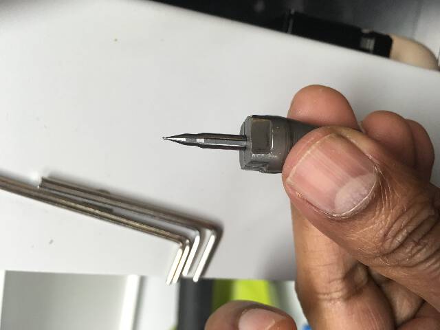
For PCB milling, there are essentially 3 different milling tools.
First is 0.8 mm which you can use for cutting and drilling holes. In this case you need to choose 2 mm/s speed.
Second is 0.3 mm which you can use for extra small parts. In this case you need to choose 1 mm/s speed.
Third is 0.4 mm. In this case you need to choose 1.5 mm/s speed.
The tips of these milling bits are ultra tiny and seem easily breakable as well. (which they are in spades!) - One does wonder if there is an underlying business model to not improve the design in order to ship parts all the time.
During the someone added anew design of a robust new mill bit
The copper plates are also known as FR-1 boards - basically a plate with a thin copper layer. The idea is for the copper to be milled away which in turn leaves traces - onto which the acccompanying electronic parts are then soldered on top.
In order to mill, one opens the server module on the mods software mods.cba.mit.edu
Click on “mill traces”
Replace web socket w the file module - open module > server module > file save
milling traces The following values are setup for 0.4 mm milling bit.
Mill raster 2d Tool Diameter 0.4 mm Cut Depth 0.1 mm Max Depth 0.1 mm
Speed 2 X=0 Y=0 Z=0 Jog height z = 2mm Home: X = 0 Y= 0 Z= 5 mm
milling edge cut /interior
Mil raster 2d Tool diameter 0.8 mm Cut depth 0.6 mm Max depth 1.7 mm Speed 1.5 X=0 Y=0 Z=0 Jog height z = 2mm Home: X = 0 Y= 0 Z= 5 mm

The basic line test performed with SRM-20
Electronics Production of the circuit boards
The Electronics production was conducted in two phases:

The 2 boards to be created are serial FTDI-UPDI FT230X and USB-UPDI FT230X.
-
“PCB Milling with SRM-20 (and Soldering) to create boards from in-circuit programmer list on the Fab Academy page.”
-
The second board is the programmer USB transfer chip (USB-UPDI FT230X).
Initially we checked the FT230X board to check components for the purpose, followed by the traces to create the base for solder. And then the interior which is the outline of the milling.
***First - what is the difference between UPDI and FTDI?
FTDI stands for Future Technology Devices International Limited, commonly known by its acronym FTDI, is a Scottish privately held semiconductor device company, specialising in Universal Serial Bus (USB) technology. An FTDI does serial communication through a USB port, and has a separate port for the TX and for the RX.
On the other hand, a new protocol was introduced for programming called UPDI - The Unified Program and Debug Interface (UPDI). This is a proprietary interface for external programming and on-chip debugging of a device. It is a successor to the PDI 2-wire physical interface.
This is used to communicate with the microcontroller on the board (to input/output the results of the calculations done by the microcontroller). The communication happens in the serial mode.
To understand the UPDI signal transmission on can divide it into TX (transmit) and RX (receive) info - one of the legs is for TX/RX signal communication while the other is the ground.
The UPDI cable has 5 V and 3.3V on either ends. Some chips use one of the two voltages.***

We made two boards - one of which was a microcontroller based “Adaptor Board (serial-UPDI FT230X)” which converts from FTDI to UPDI.
The first step was to open the traces solder base for components, using the MODS software, and use the SRM-20 machine.
Using the Roland SRM-20 milling machine
PCB milling & soldering the serial-UPDI board
We used a reference page to mark the parameters of the Roland SRM-20 milling machine - depending on the diameter of the drill bits (eg. 1.5 mm/second for the 0.4 mm bit).

All the Origins were set to zero. Jog height specifies the distance to “jump” before reaching other side of the board. For the home position, the values were 0,0,z=5 (the home position)
The double sided tape is applied to the board. In the case of serial-UPDI FT230X it is the 0.4 mm tool needed for the milling.
On the interface one can - change the step size (in steps of 10), move the milling bit around the X,Y, and Z axis. The Z axis is very important - release the set screw and place the drill bit gently over the copper plate and retighten it).
Set Original Point - set the origins once the bit is fixed in desired position (the X,Y,Z parameters then reset to zero in the interface). The bit is then lifted about 2-3mm and then the lid was closed.
Speed - reduced to lower to start with (about 50%). The one goes to CUT - and delete all previous files.
via CUT one can Add files - eg- in case of serial-UPDI FT230X add the “traces” rml file.
Finally, Then hit the output, which in this case means “confirm” so the Spindle starts to move.

The X and Y origin is apparently not to be altered for the next bit which is the cutting.
Soldering
PreSolder of the “Adaptor Board (serial-UPDI FT230X)” :
 Post Solder of the “Adaptor Board (serial-UPDI FT230X)”:

Challenges: I was not used to soldering tiny components - and last time I did solder was a long time ago. I dived straight into it, without checking the proper technique and because of this, the solder ended up really dry and the solder spots were quite bad.
The copper surface was oxidizes and wasn’t cleaned - also the surface mount components needs liquid flux which I did not add. Perhaps will be able to do a better job with the USB-UPDI FT230X board.
FT230X has multiple small legs - and here one can use a soldering temperature of 350ºC to 370ºC and put a little solder on one of the legs of our component. Solder this leg to the board and Solder the other leg(s) once the extreme ones are secured to the board.
Soldering comes with practise and the quality requires a few repetitions. Here is a basic chart below that shows the various solder joints and the variations in qualities.
quality chart
 from the
Solder joints quality chart@ the 48 minute mark onwards.
from the
Solder joints quality chart@ the 48 minute mark onwards.
PCB milling & soldering the USB-UPDI with the FT230X FTDI chip
The FTDI board was a more challenging chip to mill and especially solder.
Steps
First one has to mill the traces, hence the trace file is opened with mods software (mods.cba.mit.edu)


Once the traces.png file is imported into the software, the mill bit diameter is adjusted to 0.3 mm for the new board. The cut depth remains at 0.1.
One important setting for the SRM 20 MILLING machine is to adjust the speed 1 mm/s (recommended for 0.3mm)
The path is then generated by hitting ‘calculate’.
After the traces file is saved, next we import the outline. The mods software is adjusted for milling as previously, 0.8mm for cutting, 0.6 step down cut depth value and 1.8 mm maximum depth.
After hitting ‘calculate’, its time to work with the Roland SRM 20 interface.

The set screw is released with allen key, to first insert the 0.3 mm drillbit. It is set a bit deeper to give some room for adjustment later.
The interface is used upto a reasonable height for manual release of the drill bit so that it just touches the surface. After this the set screw is used to adjust the Z.

Once the correct position for x and y is found, the X/Y is set on the interface. This is the last step before cutting proceeds.
Speed is at 50%. After this the traces file is imported and then the machine starts executing the trace.
note: Its important to trace first and only then cut - because if one cuts first, the piece in the middle is more likely to shake (due to the 0.8 mm gap between the trace and rest of board) and precision could be lost.
After the milling is done, it is time to move onto the soldering.

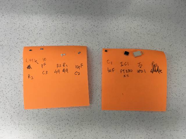
The FT230X FTDI UPDI circuit
The components needed are - R3 resistor (4.99Kohm) and RI and R2 resistors (49ohm each), C1(1μF); C2 and C3 capacitors (10pF each), J2 UPDI component and a trace for the JI USB. The programming unit the IC chip FT230XS which is a 16 legged chip.
For soldering I referred to this great manual:


In addition some of the accessories missing from the previous soldering attempt, including agents for cleaning the copper surface in addition to adding flux for ensuring the solder works more efficiently and does not dry out.
desoldering_copperstrip from Ranjit Menon on Vimeo.
soldering minute components was challenging - the 16 legged IC chip needed use of desoldering braid extensively - which only worked on third attempt from ripping the legs off.

Using the Roland MDX-40 milling machine
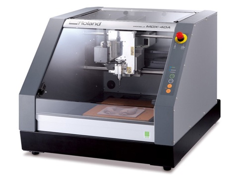
Roland Modela MDX-40 is a versatile milling machine that can be useful for many precision milling tasks. It has 1/100 mm resolution which can be useful when producing high-detail objects.
One can make simple projects such as engraving text in a piece of wood to PCB milling (removal of copper from a copper-covered FR1 clad), 3D milling modelling wax for high precision silicone molds or small-scale 3D objects with the help of the optional 4th axis.
More versatile than the SRM-20, the MDX-40 can be used for Modelling wax, Sikablock (Polyurethane block), FR1 copper clad, Wood and Plastics.
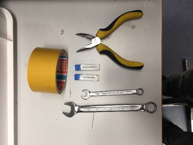
The accessories we need to setup include the copper plates, drill bits, tape and in the case of the MDX-40, couple of wrenches to tighten and loosen the mill bits.
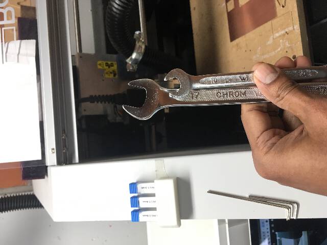
The wrenches to tighten and loosen the milling bits.
1. Prepare the Copper Plate
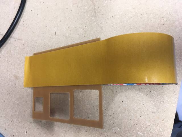
Applying sticky tape on the part you are going to mill.
2. Mod settings on MDX-40
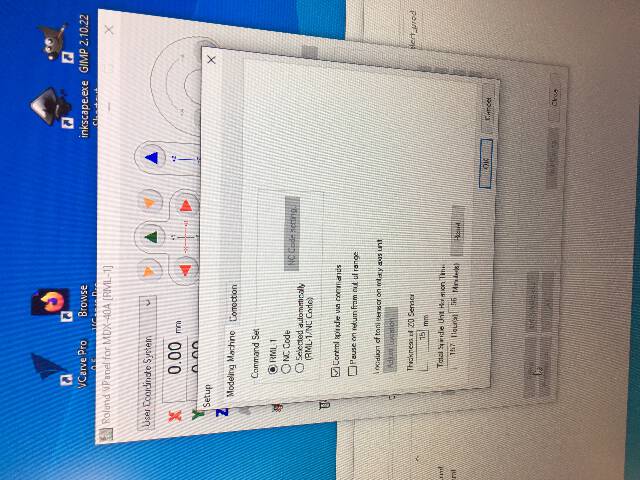
One needs to set the MDX-40 and select the command file to select RML-1.
On the computer open the file via mods software.
Right-click in Mods Programs > Open Program > Roland srm-20 > png PCB MOD: Read PNG >Open PNG
milling traces
The following values are setup for 0.4 mm milling bit.
Mill raster 2d Tool Diameter 0.4 mm Cut Depth 0.1 mm Max Depth 0.1 mm
Speed 2 X=0 Y=0 Z=0 Jog height z = 2mm Home: X = 0 Y= 0 Z= 5 mm
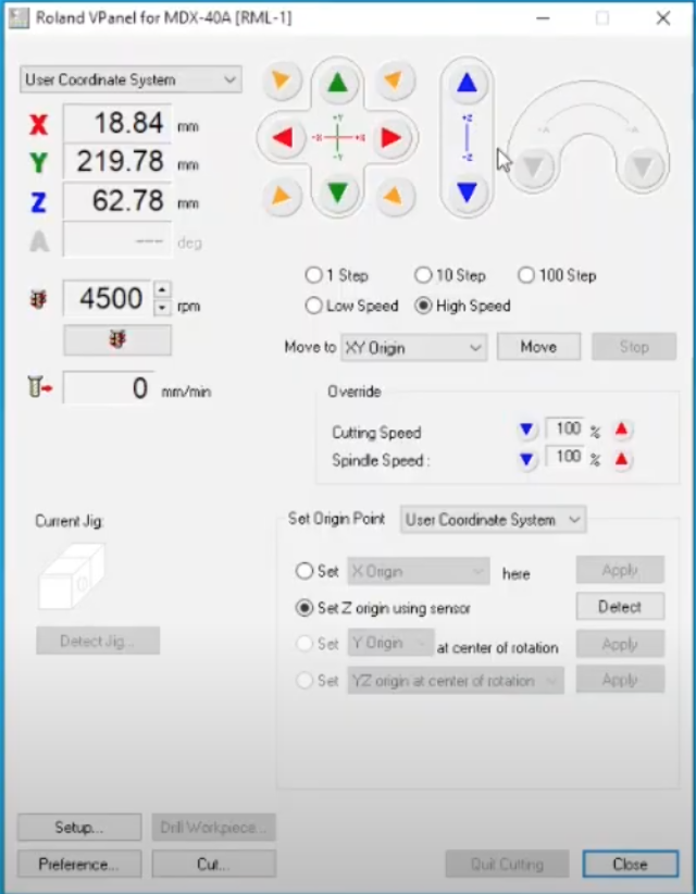
The UX is a bit more easier on the eye and has all functions laid in a gestalt friendly manner. One can move the x, z and y axis using a high or low speed or in steps of 1,10,100. Similarly, the cutting and spindle speed can be adjusted and / or overdriven.
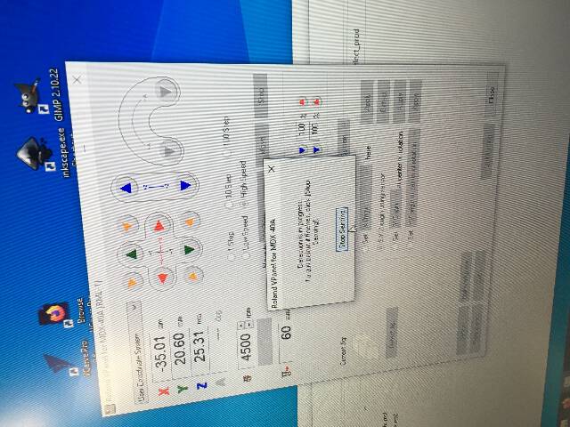
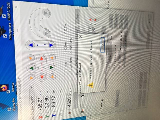
In this situation, the only thing to mainly adjust once the drill bit went in, was the Z detector.
Unlike the SRM-20, the MDX-40 has a Z detector - which means the Z does not need to be manually set in order to touch the surface of the PCB. One can use a sensor that the Z detector touches (Set via the program UI) and once detected, the value is stored for the current mill bit
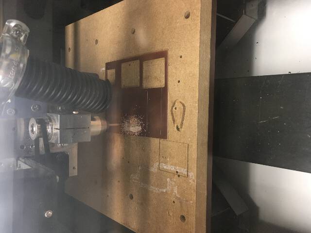
However the first cut came quite wrong. The drill simply started going way off the axis as can be seen in the straight horizontal line cut across the PCB board.
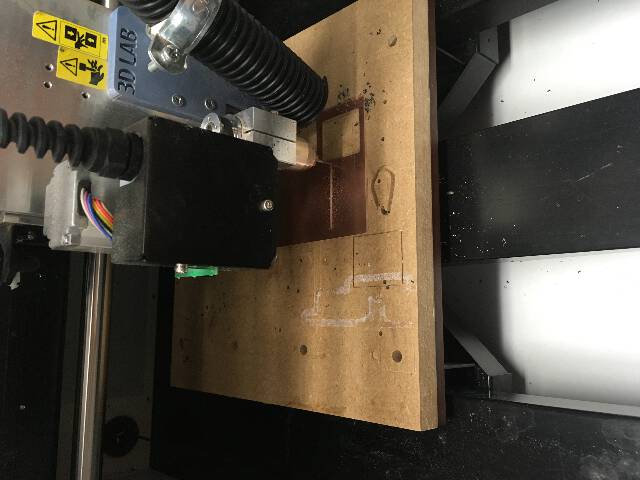
Likewise, the milling bit also got destroyed in the process as it strayed into far away corners of the platform.
For a long time I could not figure out what exactly went wrong. It was only later I realized that on the mods, the measurements of the SVG file I converted via Adobe Illustrator had changed 3mm into 300 mm or 2.5 mm into 2500 mm. As a result I sent back to Mods and chose PNG file directly instead of the SVG.
When I ran the programme again with this new value, the cut went proper.
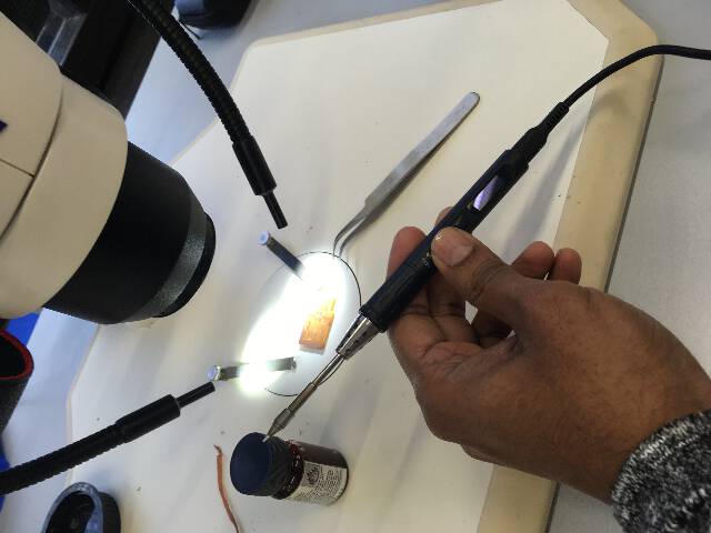
3. Soldering the PCB components
For soldering I used:
Pliers Soldering electronic pen with a thin soldering tip and a wet sponge A microscope
Steps:
Draw the components on the paper and if possible use a sticky paper (I use post-it notes to adhere the components)
Since I had soldered several times in the past before I thought this would be more or less easy. It wasn’t! The 8 legged FX230 proved to be a slippery insect - and it was a bit of challenge to also operate the microscope after being used to a magnifier for almost a year.
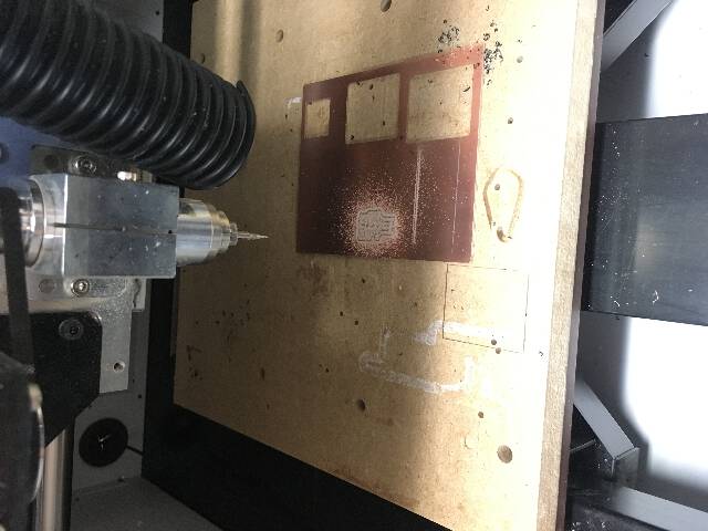
The edge copper had to be removed in order to eradicate any possibilities of shorting and to get maximum ground around the board.
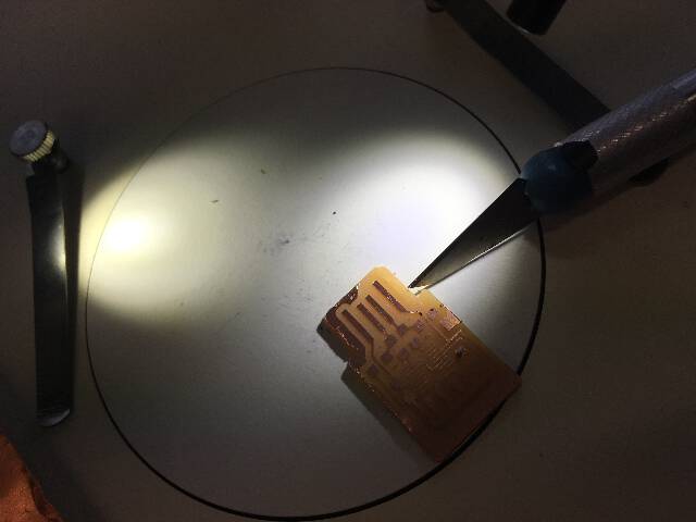
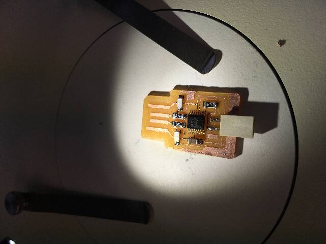
The final UPDI programmer is ready.
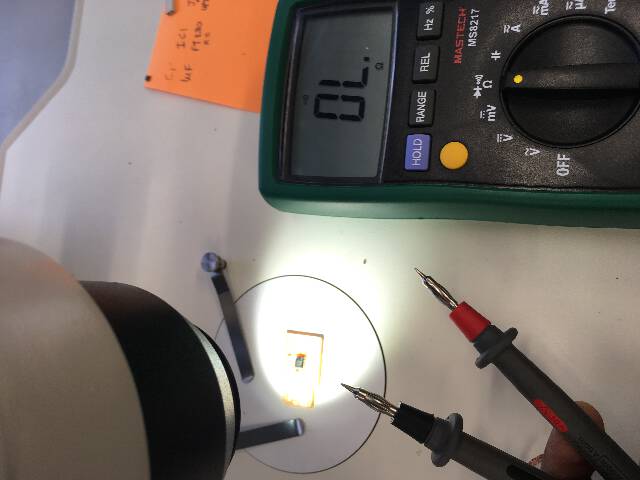
I checked all the continuity of the components with a multimeter and was happy that it bleeped in the right places.
Alas though it did not fit!
The reason was perhaps that the 0.8 mm bill bit had broken off just when it was finishing the final round, and I had to “excavate” the piece from the board.
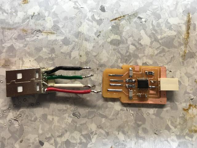
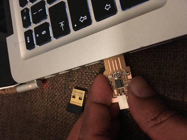
I tried to fix this by hooking up the USB lines to the jumper cables and a destroyed USB convertor/adapter leftover component which I tried to salvage somehow.
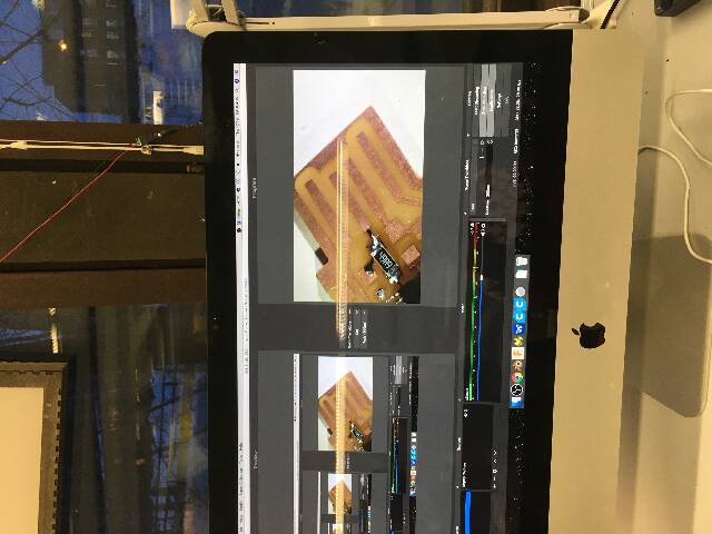
- Testing the hacked up board
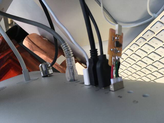
In order to test the jumper wired USB I hooked it up to an imac.
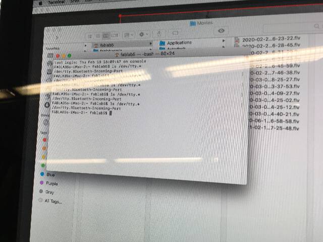
No detection!
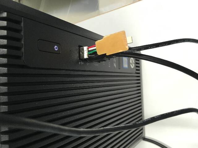
Likewise, tried the same on a Windows machine.
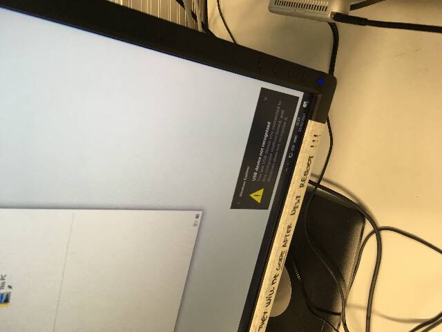
no detection here either plus a warning.
It seems that the error was that the board needed to be milled with a 0.3 mm drill bit rather than a 0.4 mm bit. However this is currently just speculation.