
Molding and casting
Week 15- Documentation
Assignments:
- Group assignment:
- Design a machine that includes mechanism+actuation+automation
- Build the mechanical parts and operate it manually
- Document the group project and your individual contribution
This week:
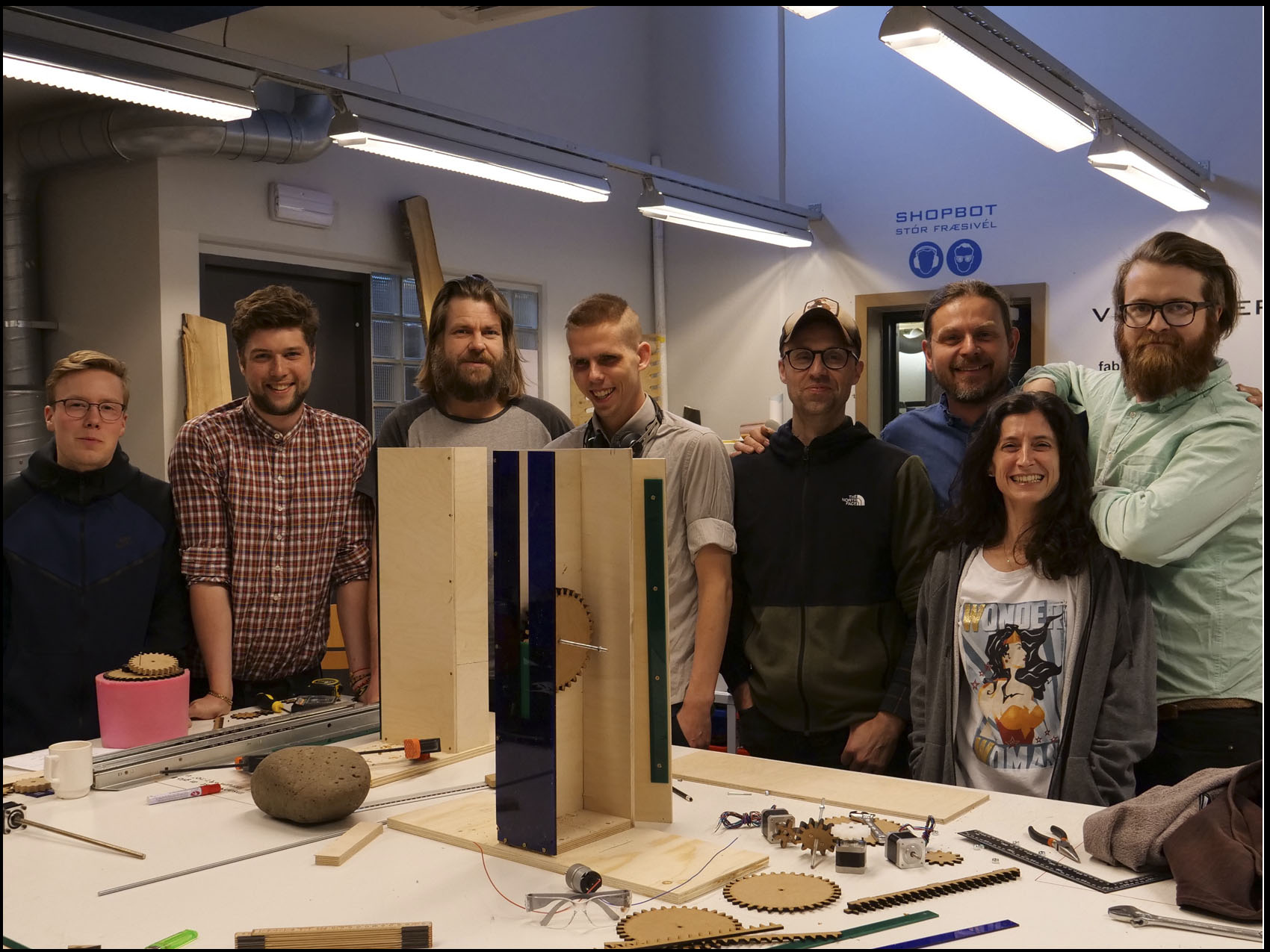
First of all, I would like to introduce the amazing crew of Fablab Iceland, students and instructors: Gísli Snær Guðmundsson, Hafliði Ásgeirsson, Thordur Hjalmarsson, Arnar Daði Þórisson, Vilhjámur Magnússon, Magnús St. Magnusson, Aida González Vicente and Jón Þór Sigurðsson.
For this week all of the students and instructors met in Akureyri to work together in the machine week.
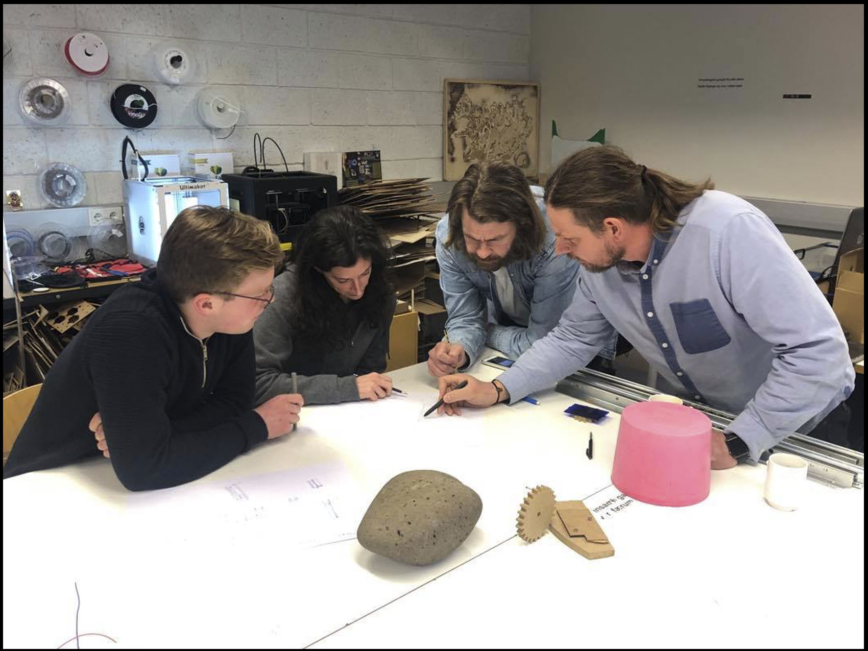
We started this week by brainstorming and sketching ideas on how we where going to make this machine. 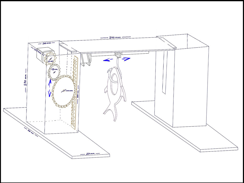
After a brainstorming, we decided to keep it as simple as possible but good and usable for another project’s development. That is a challenge. So, we came up with a preview sketches where you can see a structure is able to up and down with a hook at the middle that is able to move right and left.
After the brainstorming we split up in two groups, Me and Maggi went on to connect the TinyG and the motors and Aida and Þórður went to do the gears and frame.
Me and Maggi went on researchin and figuring out the TinyG and the motors. 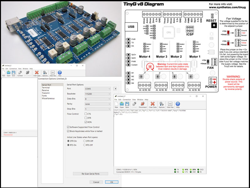
The TinyG project is a many-axis motion control system. It is designed for small CNC applications and other applications that require highly controllable motion control. TinyG is meant to be a complete embedded solution for small/medium motor
TinyG
Then we programed the TinyG, we need to communicate with it So, to be able to control the movement of the machine with the computer we used a online CNC control program called Chilippepper. Our research for this came from the Icelandic FabAcademy group of 2018
Chilipeppr
This workspace is a full-blown Gcode sender for your TinyG. The workspace connects to your TinyG via the serial port over the ChiliPeppr Serial Port JSON Server. It lets you view your Gcode in 3D, view the XYZA positions, perform jogging, and see advanced real-time details from the TinyG.
And on the other hand, the other two designing the frame and the gears. We decided to use fusion 360 to be able to see the design on 3D.
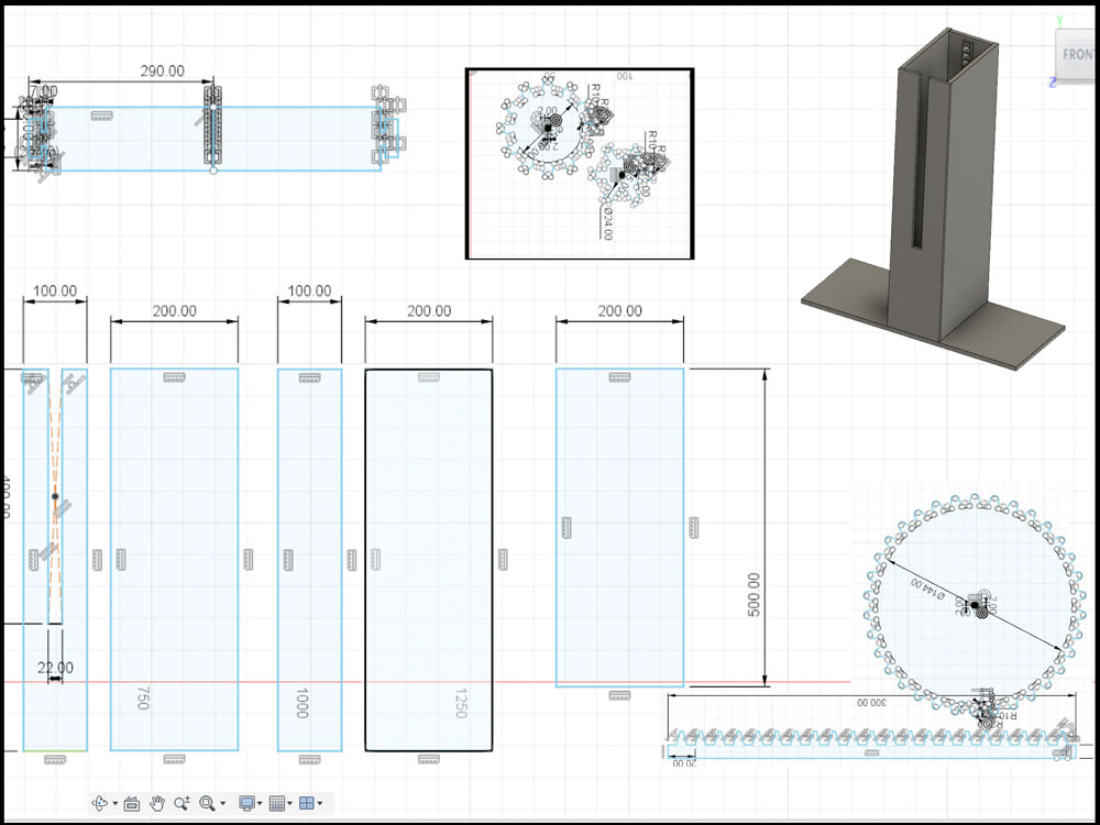
Then, we put our pieces together and split again with other functions. Two of us were building the frame. To save milling time we decided to do it with a material that we can laser cut, glue and screw together without problem and also cutting directly using the old fashion way, handmade. On the picture below is a sum up of the pieces that we used with the last design of the gears and racks.

We tested different gears ones milled in MDF and another milled in Plexy because we want to check also the friction that the force can create in addition with the material used.
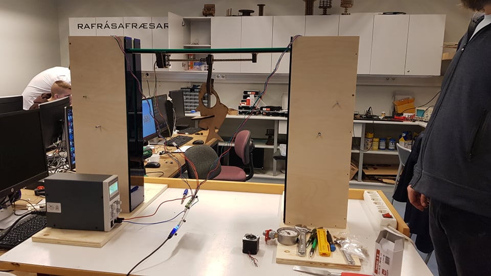
The machine looks like this:
My tasks: In more detail
We started out by sketching up and discussing how we where going to be doing out machine we decided early on that we where going to make a two axis machine like a CNC but not with a droll and or three axis. After kinda deciding on what we where going to do we splitup the group me and Maggi went on figuring out the motors and the electronics part of the projects whiel Aida and Þórður went and did the frame and gears.
Motors:
Me and Maggi started out by reading a tutrorial about the TinyG wich told us a lot about the TinyG TUTORIAL. After reading over the tutorial we followed the steps in the tutorial.Connecting the TinyG
- Check you have the correct power supply. You should have a DC power supply between 12 and 30 volts --- 24 volts is ideal. It should be capable of providing 4 to 15 amps.
- If you have a power supply where you are responsible for wiring the AC lines (like a Meanwell or some other supply with a terminal strip) - make sure the AC is wired correctly. By convention, the AC neutral is the white wire in the power cord, the hot is the black wire and the ground is green. Make sure the ground is connected. Not only for safety, but also because you may experience spurious resets if the system is not properly grounded.
- BEFORE connecting it to TinyG, turn on the power supply and make sure you have correct voltage. Make sure it is DC, not AC. Hopefully you have a volt meter or can get your hands on one. If you don't you might consider a trip to the Radar Shed for something like this one from Sparkfun or this one from Adafruit.
- With the power supply off, wire the negative to the GND terminal of the power input block, and the positive to the +Vmot side. Negative is BLACK by convention and positive is RED or YELLOW, or some other bright color. Check you have the correct voltage and polarity before connecting the power supply to TinyG. We have encountered power supplies that do not obey these conventions, and incorrect voltage or polarity can destroy your board!
- Turn on the power supply. If the blue light turns on this is a good sign. If not, blow away the smoke and send us an email.

To establish USB connetion with your host computer
- If you do not have the FTDI VCP USB drivers for your host computer you will need to install them. It's possible they are already on your system as many applications use them, including the older Arduinos.
- PC Installation - Get the latest Windows driver from the FDTI VCP Driver Page. You want the VCP driver for your host, not some of the other drivers they offer. Install and reboot your system.
- MAC Installation - As of Mavericks (OSX 10.9.x) OSX will appear to communicate with TinyG without loading the FTDI supplied drivers. However, the native mac drivers do not perform flow control with the FTDI on the v8, so they will not work. You need the VCP 2.3 driver from the FDTI VCP Driver Page. You must also reboot your system once the installation is finished (they don't tell you this). If installed correctly you should see something like usbserial-DA00Y5MM when you scan for new serial ports.
Note that the Mac native driver will also show the usbserial port, so the only real way to tell if you have the FTDI driver is to look in APPLE_IN_THE_UPPER_LEFT_CORNER / About This Mac / System Report / Software / Extensions for FTDIUSBSerialDriver, version 2.3)
Set up Coolterm
Once you have the FTDI drivers in place you will want Roger Meier's Coolterm to connect and test your tinyg. Coolterm is a terminal emulator that provides command line access to TinyG and can also stream files to TinyG. We use Coolterm as the preferred way to test the board without introducing variables from advanced UIs and host controllers such as ChiliPeppr, which is a better way to actually run jobs once you have the system set up.
- Download and install Coolterm. For the Mac we have noticed that the latest version (1.4.5) does not do well on large file transmissions. So we still use version 1.4.3. This is available on the Coolterm page under Previous Releases.
- Go to the Options menu and Re-Scan Serial Ports. You should see something like usbserial-AE01DVWD or COM12. Configure the following settings:
- 115,200 baud
- 8 data bits
- no parity
- 1 stop bit
- XON flow control (or use CTS, but make sure the $ex setting agrees)
- It's also useful to set the following - but not strictly necessary
- Options/Terminal - Line Mode
- Options/Enter Key Emulation - CR
- Hit OK to leave the Options menu
Test connection to TinyG
- Hit the "Connect" button. In the terminal enter a few carriage returns (May need to add a space before enter). TinyG should respond with prompts. If not, hit the reset button on the TinyG. You should see some JSON startup messages wrapped in JSON curly braces something like this:
{"r":{"fb":371.030,"fv":0.950,"hv":7.000,"id":"9H3583-RMP","msg":"Loading configs from EEPROM","f":[1,15,0,8891]}} {"r":{"fb":371.030,"fv":0.950,"hv":7.000,"id":"9H3583-RMP","msg":"SYSTEM READY","f":[1,0,0,8820]}} tinyg [mm] ok>
If not, go back and check your driver, your serial settings, your USB cable, and that you have a blue light and not blue smoke. For help from the command line enter 'h' for TinyG help, or '$h' for configuration help - If you simply cannot connect try powering down the TinyG and quitting Coolterm (or your terminal program), powering back up and restarting the terminal. There is a known bug in the FTDI drivers that can cause this sometimes.
- The default flow control for TinyG is CTS, which uses the following settings:
- Coolterm: CTS checked
- TinyG $ex=2
- XON/XOFF flow control is also available. Both Coolterm and TinyG must be configured the with these settings:
- Coolterm: XON checked
- TinyG: $ex=1
Verify Flow Control Once you are connected it's a good idea to verify you have the correct flow control settings
Wire Your Motors
It's best to wire your motors when they are not yet in your machine. This way you can test drive them without worrying about mechanical issues such as excessive friction or crashing into the side of the machine.
If your motors are already in a machine sometimes it's easier just to use one or more spare motors rather than remove them. It will not damage the TinyG board to drive an axis with no motor attached.
But first, turn off the power to TinyG. Never connect or disconnect anything (except possibly USB) with the power on. 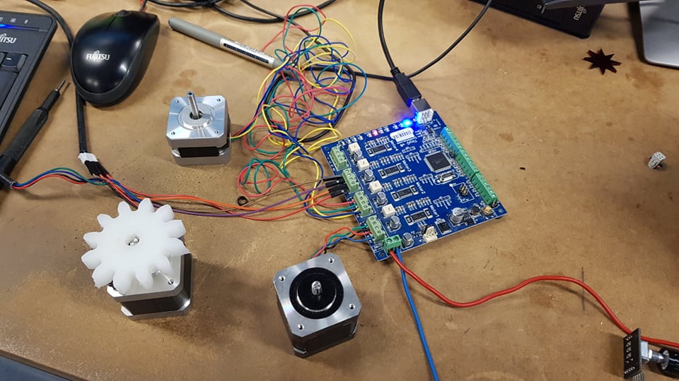
Motor Connectors (was "Synthetos Connector Kit")
Most TinyG v7s and above have screw terminals and therefore do not need a motor connector kit. If you have a board that has quick release headers on it here are the mating parts:
- Terminal Shell - Molex 09-50-3041 (need 1 per motor)
- Crimp Terminals - Molex 08-50-0134 (need 4 per motor, and usually some extras)
- TE/Amp 3-644463-4 (need one per motor)
You need 4 terminals for each housing (shell). You can get these from Mouser or DigiKey. TE/Amp also makes some nice parts with the shell and terminals all-in-one:
Chilipeppr
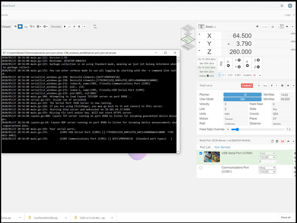
After we had installed chillipepper we went to the serial settings and we found out that we needed to install the serial port for json. We downloaded it from this link and used version 1.8
After we had downloaded that we could find the serial port from the serial port settings in chillipepper and we selected the port.
When we had connected to port and then we typed in the serial port command: G1 X 100
And nothing happened but then we closed everything and opened json 1.96 and tried again and then it worked.
When we type in x motor 1 starts and y is for motor 2 and z is for motor 3.
We found out that motors 2 and 3 are connected together witch is perfect for us because we are going to be using 2 motors that are going in the same direction. Also you always need to have the server open in the command prompt.
After we had done all that we could move the motors by using the arrow keys on the keyboard or clicking on the screen and all we nedded to do with the motors was to connect them to the frame and gears.
The spliff donk og gengja:
The Spliff donk and gengja is a piece that was supposed to fit inside the gears to hold it in place on the circular surface of the stepper motor. The Spiff donk og gengja is circular on the inside but not so much on the outside to increase friction and hold it in place. Also there is a hole on the side witch is for a screew that would tighten it to the stepper motor. We then later decided to not use the spliff donk og gengja and instead just filed one or two flat surfaces on the stepper motor witch was a much better solution.
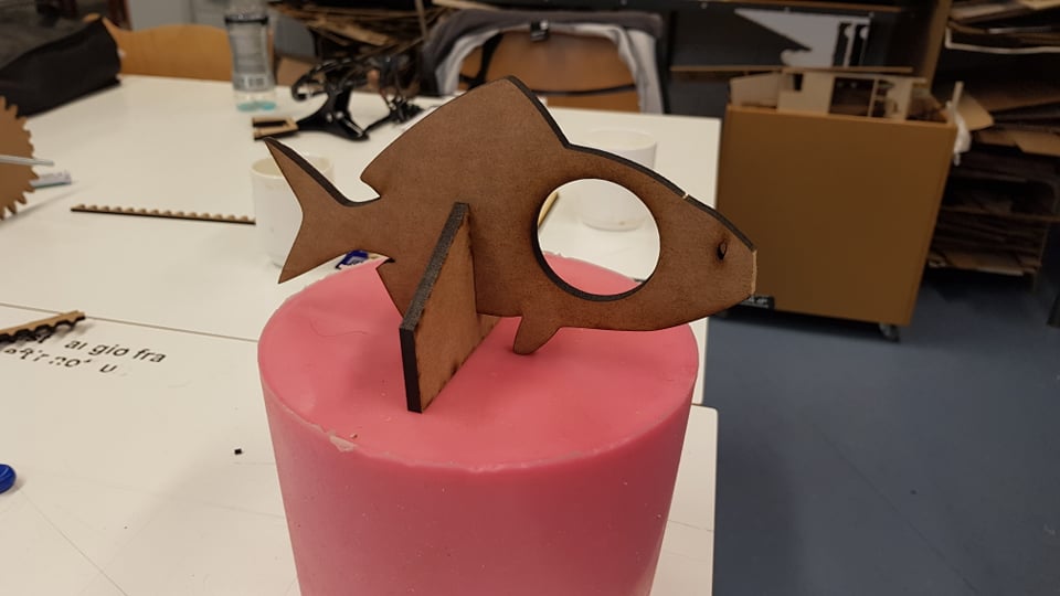
The fish and hook:
For the machine we had this fun idea to have a hook on the end of the machine so I went on to design a hook for the machine. I started out by finding an image silouette of a hook then I inserted it into Inkscape and there I made it into a vector format, changed it a little, making it a little bigger and then I cut it twice out of MDF and glued them together and drilled them to the platfor that goes on the stepper motor.

The bridge:
The bride is the component that goes up and down with the hook motor and connects the two pillars. I made the bridge out of two pieces of plexi glass and plywood for structure. To connect the motors I measured the motor and made a frame that fitted perfectly around the motor and then I glued it to the plywood. I also made a similar for the end rod of the motor but in first there where a lot of friction from the glue in the frame so I needed to loosen it a little bit up. 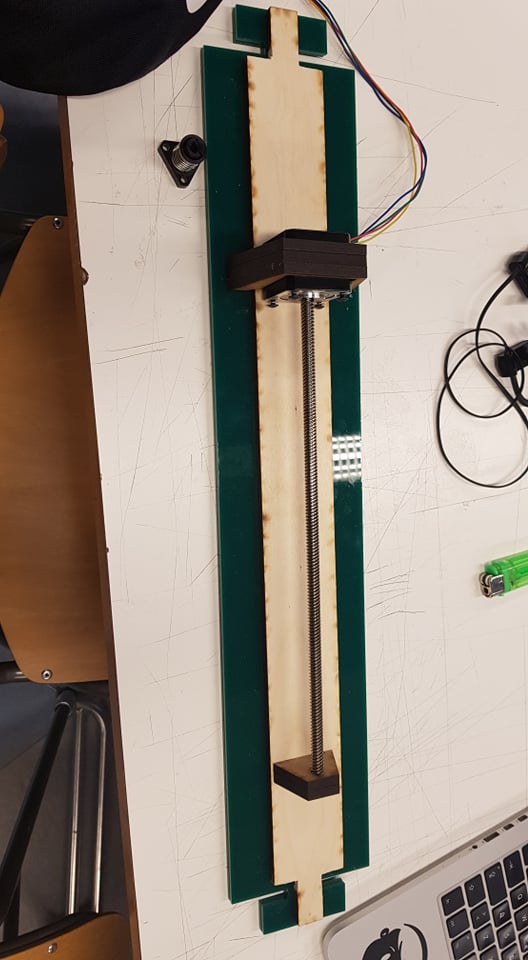
Link others documenttations:
- Aida: Machine week
- Maggi: Machine week
- Þórður: Machine weeknot yet uploaded