Final Project
Varða
Assignments:
- Complete your final project, tracking your progress:
- what tasks have been completed, and what tasks remain?
- what's working? what's not?
- what questions need to be resolved?
- what will happen when?
- what have you learned?
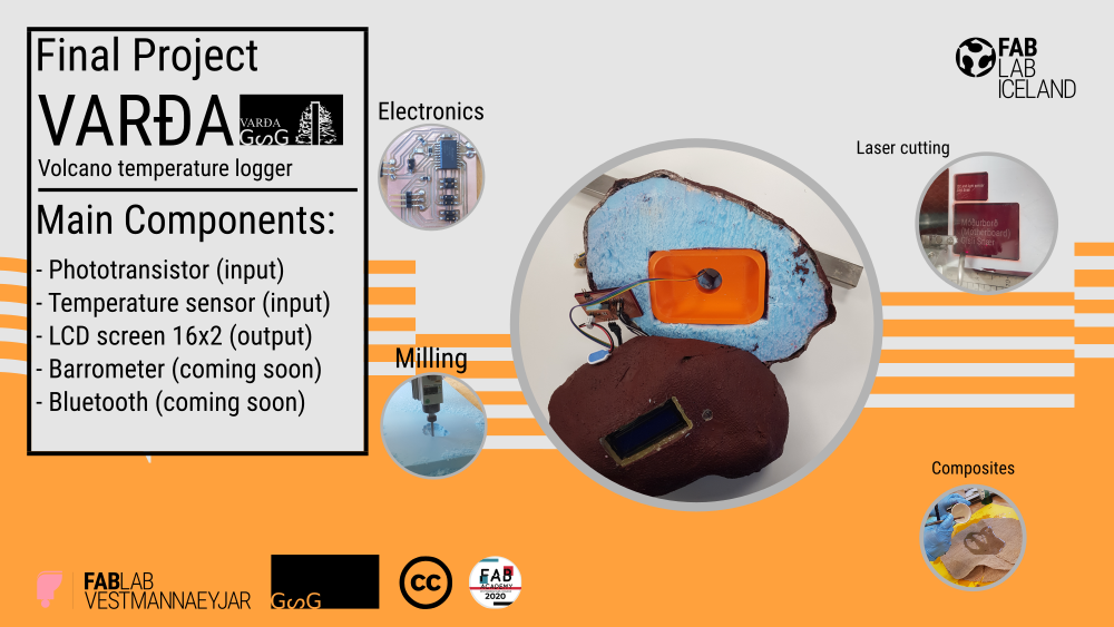
Varða: Volcano temperature logger
Final slide and video:
More about the project:
shell:
Composites:
The composites was part of my wildcard week assignmets and in that week I choose to use composites to create the shell for my project.
- I started out by opening last weeks mold design and scaling it up in VCarve pro.
The mold is two half molds that combined make the rock. After scaling it up I then set it up in VCarve and made it ready for a cut. - After making the mold ready for a cut all I neded to do was to glue and making sure that the foam board that I was cutting was secure in place and starting the cut.
- After I had cut out the mold I removed it from the CNC and cut it out with a knife.
- After removing the molds I realized that I had made the same side twise so I took a sandpaper and sanded one half out so he would fit the other half
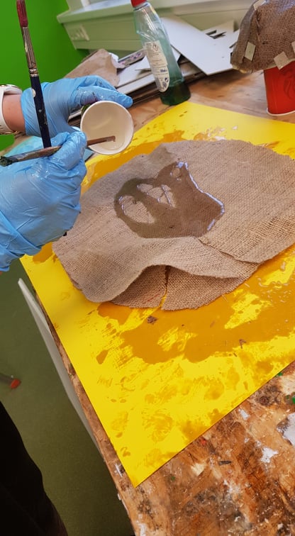
- After that mistake I then found a cloth that I was going to use and cut out a pice that would fit on the molds. I cut out a couple of pices for each side. The cloth that I'm going to be using is a cloth that is used to package dry fish in the fish drying company in my home town.
- After cutting out the cloth and I made sure that it fitted around the molds it was then time to make the molds ready so I wrapped the molds with a protective film and then I placed soap on the film to make it not stick to the molds.
- After the molds where ready I then mixed the epoxy. I mixed them 2/1 by volume. I mixed 2 of the epoxy resin and 1 of the hardener. After placeing both materials in the same cup I stirred them together untill they where well mixed togehter and then I started to paint the cloth with it until the cloth's where soked in it. I used four cloths, two for each side.
- After painting the cloth's I placed them on the molds (two on each mold) and pinned them down with metal pins. I put a piece of vinyl sticker material on each pin so the pins would hold the material down. After pinning it well down it was time to let the it dry over night.
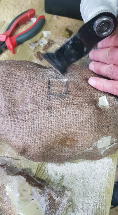
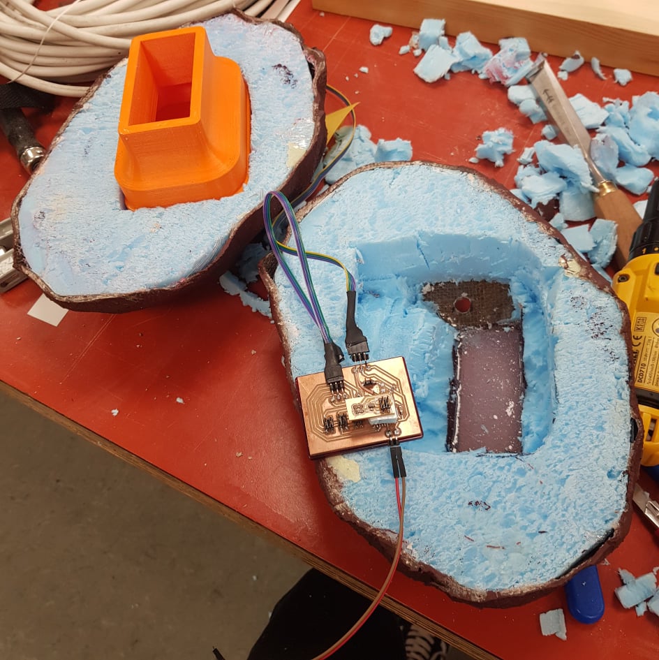
- After it had dryed over night it was time to take the pins out and making holes for the screen. I decided not to take the foam out because then I would need less material to fill the space. I marked the area that I was going to cut out and then I cut it out with a machine (multi vél in Icelandic). After cutting the composites I removed a space for the screen in the foam by cutting it out with a knife. I also made a hole for the light sensor by drilling a hole next to the glass for the screen with a 10mm drill.
- After cutting holes for the screen and the light sensor I then removed the foam from the composites and made space for the circuitboards and sensors.
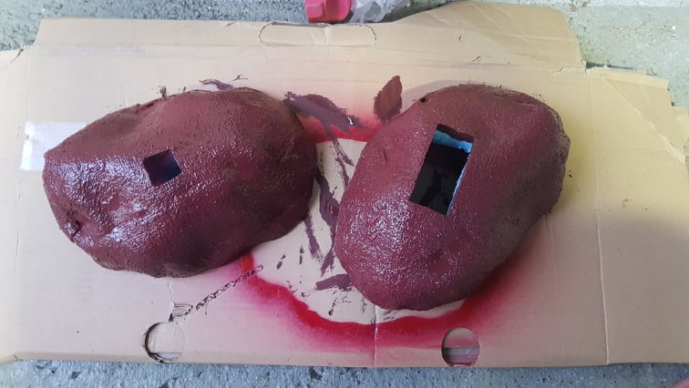
- After removing the foam it was time to paint it. My mother asked if she could help so she painted the composites shell like a red volcanic rock like that can be found on Eldfell the mountain that the Varða is made for.
- After painting it and waiting for it to dry I poured a clear silicone rubber in the hole for the screen to try to make it fit the curve of the rock by placing protective film on the shell and taping it to it. After placing the film I mixed the silicone and poured it into the shell. (see more on molding and casting at molding and castingweek)
- After placing the circuitboard in the shell via toothpicks I was not wery happy with it so I decided to use a 3D printed case that I had printed previoucely so I made a place for that box inside the rock. I accidentally removed too much area inside the rock so it was a little bit more messy when I was glueing it with hot glue.
- Before I glued the box in I glued the light sensor in with tape and hot clue and made sure that the sensor chip was looking out the hole that I had made previoucly.
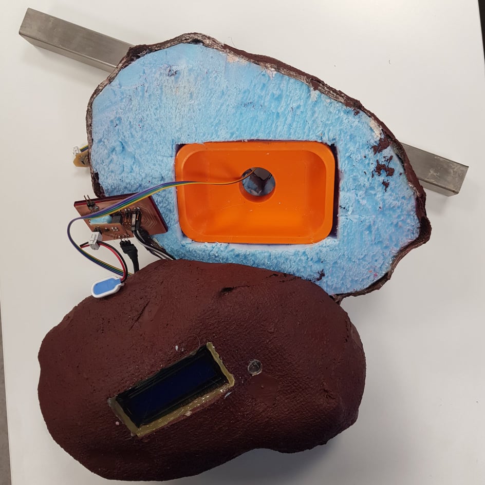
- After glueing all of the parts together I decided that I did'nt like the slilicone rubber that I had put in place as a glass for the screen so I took out the sislicone and cut out a plexi glass to fit in the hole for the light sensor hole and the screen. After cutting that I with the laser I then glued it in with a hot glue.
- At this moment all I needed to do was to place the iron tube for the tempreature sensor in place on the bottom in the hole that I had made for it when I was cutting all of the holes out. I was going to glue it shut with a hot glue but stopped at last secont because I needed to travel home with it and it fits better in my bag not with the tube.
- After the shell was ready all I needed to do was to put the motherboard in it.
3D printing:
The 3D printed case that is in the shell was originally made for another idea of the shell and in that idea the screen was sticking a couple of centimeters out from the rock. I because the shell was a lot bigger than the box I was able to fit it inside the shell. 
- I Started out by exporting my Fusion model as an svg file.
- Then I opened my svg file in Cura.
- I wanted to have a build plate and no support. The reason why I want to have a build plate and no support is that build plate makes the collums stable and the print that I did previous had no build plate and the collums where somwhere not in the right place and the reason behind the no support is that I wanted to test the printer with all those bridges and also the support is just pain in the ass to remove.
- To be sure I made the infill 90%.
- When I had finish with the settings I saved the file to a removable drive that is used with the 3D printer.
- After saving the file to the drive I inserted the file into the 3D printer.
- Then I found the file on the 3D printer and pressed print.
The setting for the printer is:
- Build plate: 60 deg C
- Temp.: 230 deg C
- Speed: 100%
- Material flow: 100% - Also make sure that your build plate is level. WERY IMPORTANT.
- After the printer is done with the project you collect the model and then remove the build plate support.
Circuitboards:
For this build I had to design and build a couple circuitboards; temperature sensor, light sensor, battery regulator and a motherboard.
Motherboard:
The motherboard is where it all happens, it takes data from the sensors and sends it out to the LCD screen where they are shown.
Components:
- Attiny3216
Phototransistor board:
The idea of having a phototransistor sensor in this project is to see the amount of daylight and with that raw data in the future the rock clould say "good day" if the data from the sensor vould indicate it was bright outside and so on. In the project as it is today it only shows a raw data from the sensor. On the shell of the rock is a small window for the light sensor.
Components:
- Attiny412
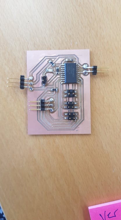
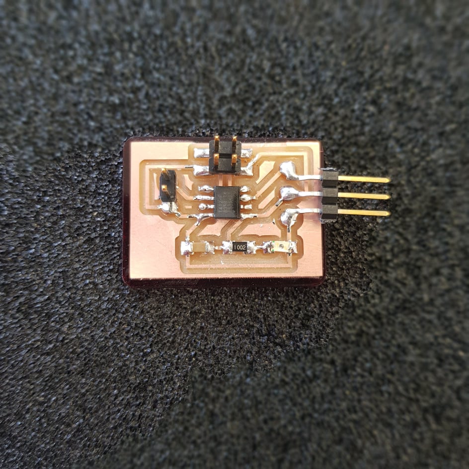
Temperature board:
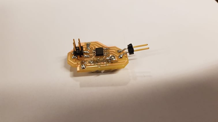
The temperature board is designed to be placed far away from the motherboard and I'm going to be placing it in the ground to measure the heat in ground of a active volcano that last erupted 1973 in my hometown (Eldfell). The board gets it's power from the motherboard. The board has a thermometer and that data is processed in the attiny412 that the board has and after the attiny412 has processed that data it sends that data to the motherboard and by doing that I'm decreasing the pressure on the motherboard by making it do less work.
Components:
- Attiny412
- 10k resistor x3
- 1uF capasator
- Thermometer
- 2x2 connector
- 4x1 connector
- 2x1 connector
I started out by going throug Neil's thermometer board and I took that blueprint and changed it so that it would use the attiny412 instead of the attiny45. I also made the board 2 layers so I had to connect them by 4x1 pin connectors.
After designing the board it was time to mill out the board and soderd the componenets on it I coded it with a epoxy layer to keep it safe from vater and moisture.
Battery regulator:

The battery regulator is for the 12volt battery that I'm using for this project and what the regulator dose is to lower the voltage to 5volts so that the motherboard wont get distroyed. The regulator board is placed on top on the motherboard and then the battery is connected to the regulator and then the current goes though the regulator and comes out as 5volts.
Components:
- Regulator
- 2x2 pin connector
- 2x2 pin connector
I started out by designing the board after insructions that I got from Hafliði(my instructor). After designing it I soldered on the components and when I was connecting it to the board we found out that I had designed it wrong. So we fixed that problem by taking out both of the 2x2 pin connector and swiching them. After that we measured the voltage and where happy with it:)
Programming:
Screen:
Files and images:
Software I used:
- Fusion 360: Integrated CAD, CAM, and CAE software
- Inkscape: Professional quality vector graphics software
- Slicer: A tool to turn your digital 3D models into appealing artefacts.
- Gimp: Cross-platform image editor