8. Computer controlled machining
Objectives:
This week for group assignment we have to test runout, alignment, speeds, feeds, and toolpaths for the machine we use at our lab(ShopBot) and document the work. The individual assignment is to make (design+mill+assemble) something big.
Research
I learned about early inventions in CNC from this
I tried to understand various CNC machining operations further from here
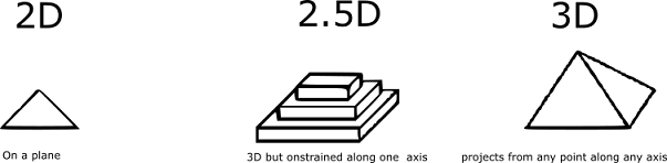
I was confused about 2.5D although Neil explained it and I learned it from Wikipedia
2D, 2.5 D, 3D is beautifully sketched by Sketchplanations
I wanted to learn what G-Code is and it’s fundamentals and this explanation helped
G-Code most important commands
Learn to program CNC milling using G-Codes
Right after Neil’s class, Jogin asked all of us to do this bookshelf tutorial from end to end before we start designing and it helped immensely.
This tutorial by Spark Plug helped me in learning how to design meshes and how to make rectangular patterns.
I was very confused about how to insert the cat face on to the design and this tutorial explains it.
I wanted to know how I can make Drawings from my design and Lars Christensen explains it in detail here
Shopbot
Material Capability- Almost all materials from Plastic and Plywood, MDF, Soft & Hardwood etc except metal or anything that requires cutting lubrication
Data Format- gcode
Gcode (tool path) Generation Software- 3D-CAM, VCarve, Fusion360 (we used Vcarve)
Data Format(2D)- svg, dxf, dwg, eps, ai, pdf, skp
Data Format(3D)- stl, obj
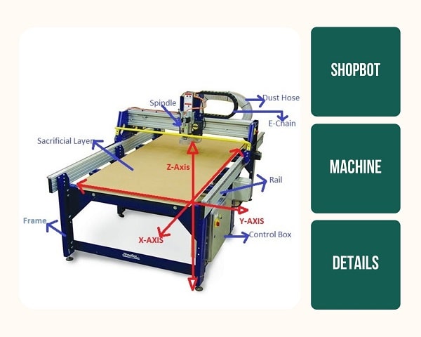
Key Components of ShopBot
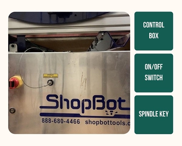
Control Box:
All the electronics are integrated into the shopbot main control box.It has a Machine ON/OFF switch and a Spindle Lock/Unlock key switch (disallows/allows milling head spindle rotation). After the Spindle key is inserted turning it clockwise once Switches it ON. The shopbot also has an additional Emergency Stop Switch placed on the other side, so that the user could access the emergency button easily from that side of the machine.
Power Distribution Box(Electronic speed controller for Spindle Motor):
Bed and Sacrificial Layer:
The bed is the cutting platform and its size is 1300mm along x-axis 1200mm along Y-axis and 150mm along z-axis. The X and Y axis are the length and the breadth of the bed respectively. The Z axis is perpendicular to the bed and its length depends on the length of the end mill. To have a rigid supporting layer on the bottom of the workpiece an additional piece of plywood is placed above the bed called the sacrificial layer.The sacrificial layer also protects the milling bit from the damage that may occur by avoiding unwantedly touching with the metal body.
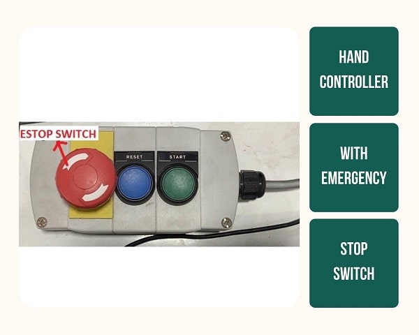
Machine Hand Controller with ESTOP Switch:
Shopbot has a wired remote hand controller which consists of an emergency Stop (ESTOP) Switch, a reset switch and a spindle start button. In case of emergency the machine can be stopped using theESTOP switch.
Stopping using emergency stop button wont resume the operation, hence it is advisable that it is used only in case of real emergency. At all other times, keep a finger ready on the Space bar key of the computer to pause the operation.
Spindle Key and Spanner:
To prevent accidentally turning on the spindle while working on the chuck, the key for the spindle is attached to the chuck releasing tool.
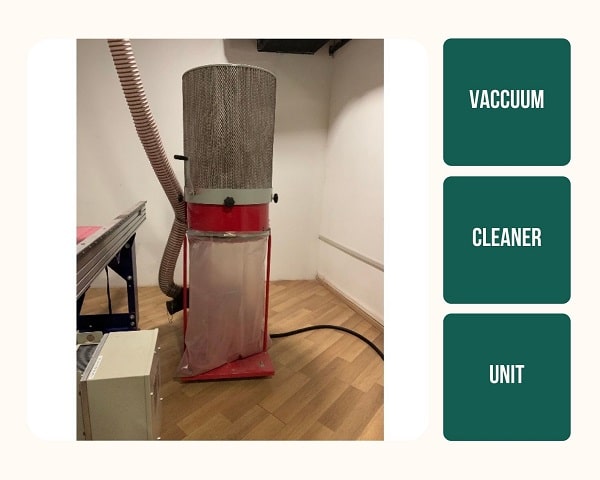
Vacuum Cleaner:
CNC machines produce large amounts of waste in the form of minute particles within a short time frame.Proper arrangements need to be in place to make sure it doesn't make the surrounding environment inhabitable. Shopbot depends on the huge vacuum cleaner for this and it suckout all the residues created during milling. The vacuum system is loud and usually turned off and must be turned on prior to starting the milling operation.
Dust Collector:
This dust collector collar is attached to the Milling head area after the z-origin is set.
Machine Head
High speed rotating spindle with a collet to hold various types of end mill bits.
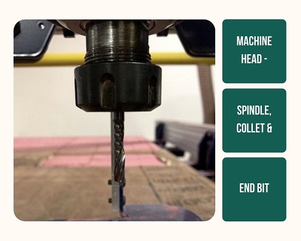
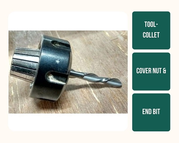
Collet:
A collet is a subtype of chuck that forms a collar around an object to be held and exerts a strong clamping force on the object when it is tightened, usually by means of a tapered outer collar. In CNC it is used to hold the tool. Here we are using ER25 collets that are slotted alternatively from either ends. This flexibility, like a spring action, allows it to compress on to the cutter along the whole length of the collet when tightened. This provides a better grip and allows flexibility to have a range of bits to fit into the same collet. We have different bits, so we have different collets. The inner diameters of these collets are different to fit in the bit perfectly but the outer diameters are the same to fit the same covernut.
Covernut:
This is the locknut for the collet. There is only one covernut for all the collets that fits the outer diameter of the collets.
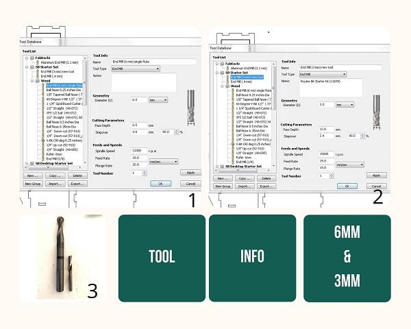
Tool:
Different materials have different properties and this is overcome the unique challenges by altering machining variables like tool selection, rpm, feed rate and coolant flow.
Understanding Bits
CNC machines need bits to drill to remove material in a specific way. They determine the kind of carving that can be done, the resolution of the finished designs, how fast it can move through the material. Drill bits come with cutting edges that pull up or push down (sometimes both), they have square or shaped ends, they are made for speed or accuracy, and they come in diameters from a pinpoint to over two inches for standard CNC routing. There are a lot of variables to be considered when looking for the best bit for a particular project.
Material Composition
Drills made from various materials are available and each can be used for a specific purpose. Commonly available bits are:
High-speed steel (HSS) bits
Solid carbide (SC) bits
Carbide-tipped bits
Solid tungsten carbide bits:
Polycrystalline diamond (PCD) bits
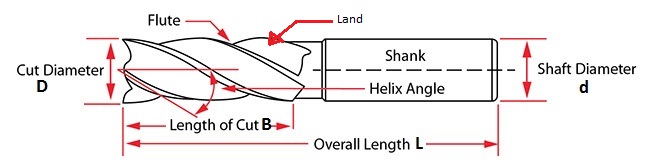
Flutes
Flute: A cutting edge of a bit. Having more flutes increases the strength of the tool this gives a faster feed rate, but it reduces space for chip flow. Thus, bits with more flutes tend to leave a smoother cut surface and require a faster feed rate to avoid burning. CNC router bits are mostly available in 1-, 2-, and sometimes 3-flute configurations. Generally, bits with fewer flutes remove more material per cut and require a slower feed rate.
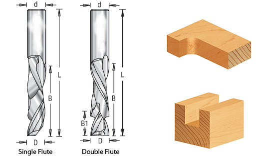
Straight Flute: A straight flute design means the cutting edge is parallel to the body (or shank) of the bit. With this design, the material will not be extracted from the cut. A straight flute is cheaper to make and is mostly for wood and plastic materials. A straight flute produces a clean finish.
Spiral Flute: A spiral flute is cut in a helix around the body (or shank) of the bit, making them ideal for wood, aluminum, and plastics. The up-spiral flute, for example, is useful for removing chips. There are three major types of spiral bits that we’ll discuss later: up cut, down cut, and compression.
Cut Types
UP Cut:
Down Cut:
Compression Cut:
Parameters to be considered
Chip Load: The size of the chips or pieces that the CNC bit removes from the material. In other words, it is the thickness or size of the chip removed per cutting edge (or flute) with every rotation. Chip load is crucial since smaller chips increase heat generation during the cutting process. The smaller chips are not ejected fast enough and are instead re-cut into smaller pieces, which results in heat generation. This can cause premature bit failure when the heat is transferred to the cutting tool. When the chips have the proper size, they will carry away heat and prolong tool life.
Chip load is equal to the feed rate (in inches per minute or IPM) divided by revolutions per minute multiplied by the number of flutes. The chip load value can help the user in selecting the right size or diameter of a bit. Some manufacturers give a target chip load.
Feed Rate: The speed at which a bit can move sideways through the material. It is measured in Inch Per Minute or Feet Per Minute. If the chips are unnecessarily large, reduce the feed rate or this will ruin the bit.
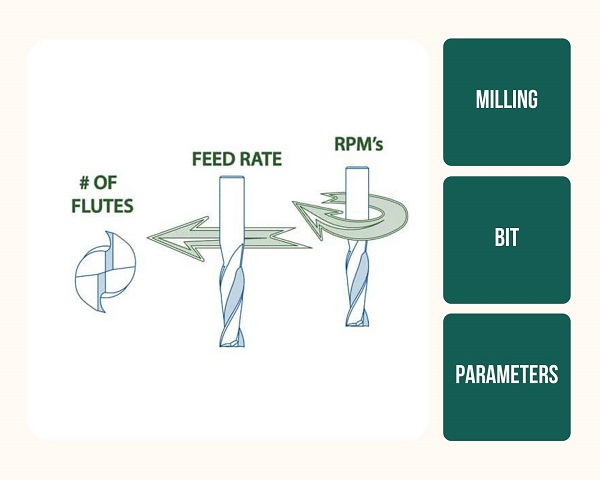
Speed Rate: This is the speed at which the spindle rotates. It is represented in revolutions per minute (RPM).
Group Assignment
Find it here
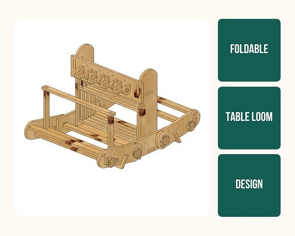
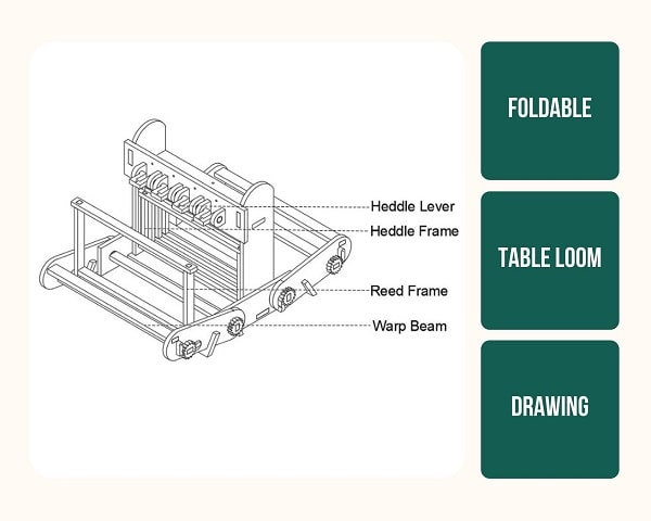
Individual Assignment
Designing somthing big
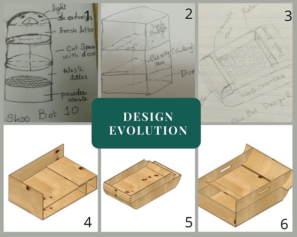
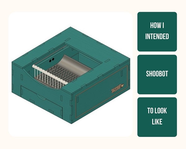
I decided to make the box required for my final project, Shoobot.
Design considerations:
1. I want to consider how the cat would be able to jump in out easily
2. The electronic components has to be enclosed inside
3. There should be a removable waste bin
4. A fun element realted to cats would be great
5. A space for adding metal inlay
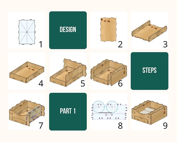
Outline of Milling Procedure
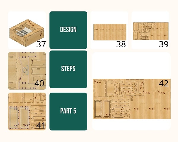
Step 1. Make a 2d Drawing of the design - I used Fusion 360
Consider the tolerance, Put the drawing in layers as per the cutting scheme, Arrange pieces to minimize material wastage, Leave ample distance between pieces to avoid overlap
Step 2. Export it in .dxf format
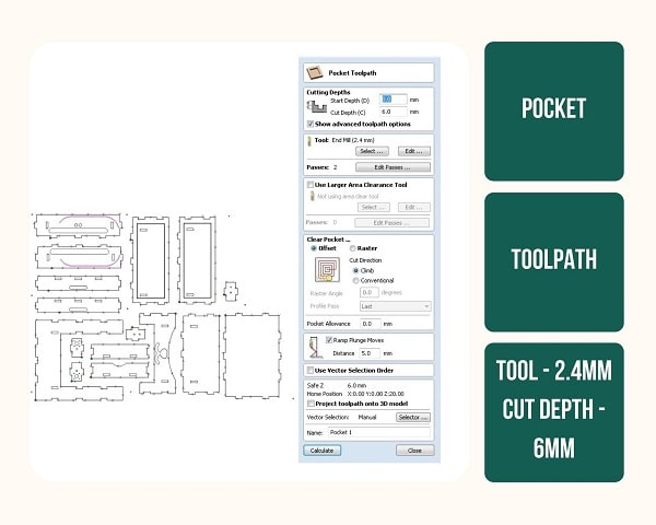
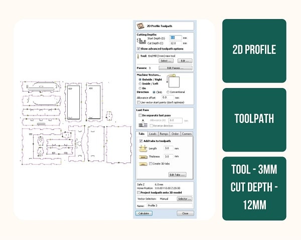
Step 3. Import it into a software that creates tool path(Fusion 360, Vcarve, Pathworks etc.), I used Vcarve
Choose the type of output(cutting, pocketing etc), Choose the orientation of the bit, Check all parameters, See the preview in 3D
Step 4. Export it as .GCODE
Step 5. Milling machine
Mount the correct drill bit, Turn on the machine, Turn on the exhaust, Rotate spindle if not used for more than 12hrs to ensure lubrication flow
Step 6. Import GCODE into Shopbot
Step 7. Set x,y,z zero(Origin)
Step 8. Start milling process
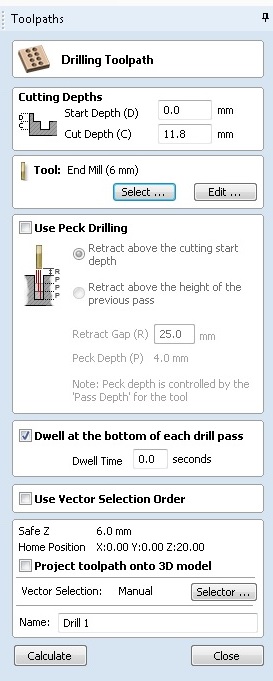
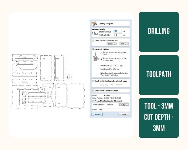
Making Toolpaths
Vcarve
VCarve Pro software is a solution for CNC routing, sign making and engraving. This software can import our designs from other programs like Fusion 360 and create G-codes. It also contains inbuilt design tools. The software can create all the typical tool paths that are required such as profiling, pocketing, drilling.
A tool path is a coded route that the machine follows to cut, it acts as a guide for the device to move.
Complete control of the tool paths is possible with tool libraries, feeds, spindle speeds, step overs and depth per pass options. The tool paths can be simulated in natural materials and colors to provide presentation ready renderings before cutting.
Open the file in Vcarve.
Under Job Setup change the units to mm
Using the Circle tool in the Create Vectors under Drawing, mark the screw holes on four sides of the material.
Add dog bone to corners
The holes to secure the stock.
By
Take the 3D view tab on the top
Open vcarve for shopbot
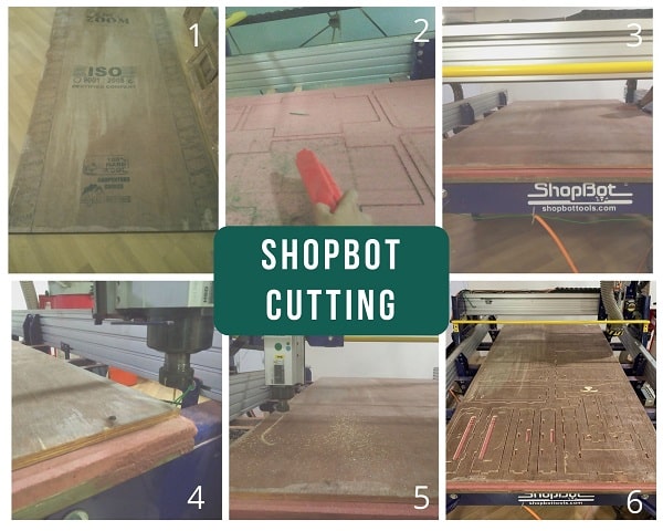
Shopbot Cutting
Parameters
Give tabs using Add Tabs to the tool path
Preview
It is possible to change the order of the files cut
Save files
Handling of the Machine
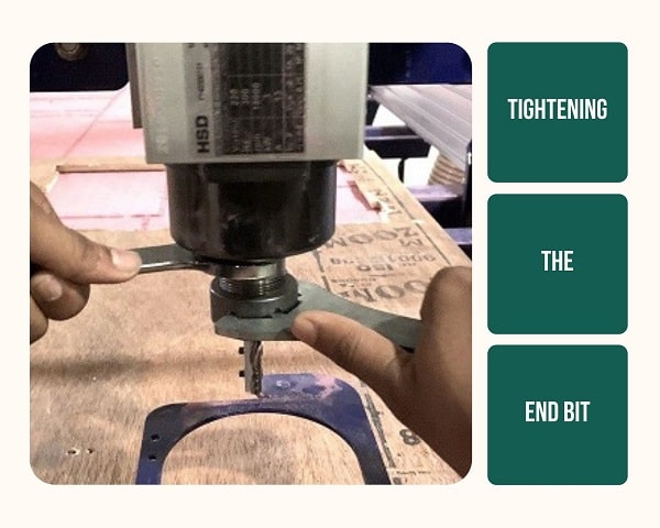
Step 1. First the appropriate collet for the bit is put in the lock nut and turned to hear the ‘tick’ sound, then the bit is inserted. After this, the locknut set is placed on to the shopbot head. How much of the bit is to be inserted inside the collet depends on the Cut Depth. If the cut depth is more, do not insert too much and if it is less, insert more.
Step 2. To access the spindle remove the dust collector. There is a ring on it that acts as a lock and once it is pulled up, the collet can be accessed.
Step 3. Hold the bit with one hand and tighten (move in clockwise direction) the covernut. The hold the second spanner on the flat shaped part of the spindle, With the other hand use the big spindle spanner to tighten it by applying the whole body pressure. Double check that it is tightened.
Step 4. Once tightened, the dust collector needs to be replaced. The ring should be pulled up again to place it and then pull down. The height at which it should be placed depends on the bit and depth of cut. If it is 18mm then place the dust collector at 12mm. Initially there will be a gap, but once the machine starts its action, it will be correct.
Step 5. Set Milling machine XY origin automatically by pushing the set XY Button
Step 6. Set Z origin- This is done with the help of a conductivity plate Two people have to do this step together as one person has to hold the plate while the other works the PC controls. First the conductivity must be tested by touching the metal plate to the end mill tip. Then the Z origin can be set by slowly moving the ned mill down until it touches the metal plate kept flat on top of the sacrificial layer
Step 7. Fix the material to the sacrificial layer using screws
Step 8. Start the milling process
Step 9. Turn on Dust collector
Step 10. Dis-engage spindle lock by turning the Key
Step 11. Run the cut file, spin up the Spindle
Step 12. Click okay to mill
Step 13. Observe the milling process attentively from beginning to end
Precautions
- Check that the cutting bed with the stock is free of any tool or anything before the start of operation.
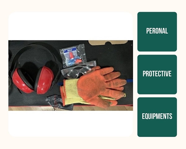
- Wear covered shoes,gloves,masks and goggles and ensure that no one reaches into the machine , when it is in operation.

3. Machine should not be left unattended during operation. At Least two people shall be there during the operation. 4. Stock is usually screwed onto the sacrificial layer, it is to ensure that sufficient clearance is kept between the machine head and these screws.
Things to be careful
- The profile is usually an outside cut, so when we give the cut for screw there should be sufficient gap between these two.
- Between two profiles the X and Y has to be brought back to origin. If this step is forgotten, the machine will start cutting from the existing point.
- Giving tabs
- Always keep the tools back in the toolbox after use.
Mistakes and Learnings:
Mistake 1. While designing the box in Fusion 360 I did not ensure that each sketch eas constrained. This will not give a parametric design as output. The sketch would have been black in colour if it was parametric.
Luckily I didn’t have to change any parameters, but had it not been the case My design wouldn’t have worked well. But I learned from this how to make a parametric design for shopbot milling.
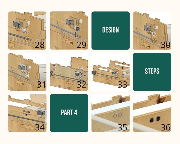
Mistake 2. On both sides of my ShooBot outer box I designed a 2mm pocket where I can insert Brass wire to do metal inlay. While designing I did not consider the milling bit that we used. I had to give it 3mm and I should have purchased a 3 mm wire but as I had a 2 mm wire, it would go in and won’t look like inlaying.
Mistake 3. While joining each component on to the wooden sheet I made the mistake of chosing the wrong side of one of the outer boxes to come on the top. I chose the inside and ended up getting the pocket on the inside.
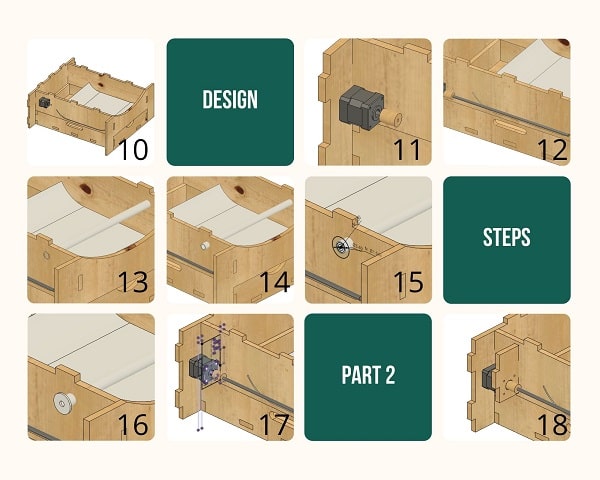
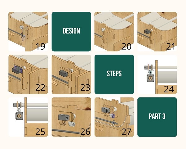
Mistake 4. When I designed i didn’t correctly assess the size of the Servo Motor that I used. Hence, when I assembled everything including electronics, a part of the Servo Motor was jutting out hitting the outer box. So I did a temporary fix using Acrylic while presnting to Neil as it couldn’t be perfectly inserted.
To fix it I made a pocket on the insides of the outer box that can accomodate the servo thickness while moving from one side to another.
Finishing the box
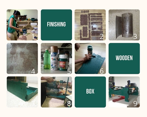
I sanded it, painted it using Fabric paint added the perforated sheet, other parts and assembled it.
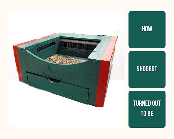
ShooBot
Here is how it finally looked like.
Individual Assignment -2
Files
Find my files here