14. Embedded Networking and Communications
Objectives
This week’s group assignment is to send a message between two projects. As an individual assignment I have to design, build, and connect wired or wireless node(s) with network or bus addresses.
Planning, Files and Tools
Planning
Upload trello board here
Files
Mater program
Slave program
Tools
Eagle
Arduino IDE
Link with final Project
I would like to combine my input device with my output device through a wired network. I will use the PIR sensor board from the input devices week and I want to connect it to the DC motor board, and I want the DC motor to start working only a certain time after the object has left the sensor area. But this didn’t go according to my plan as I didn’t have a pull up resistor on my output board and I ended up using hello blinky board with my input board.
Research
Rheingoldheavy
Engineers garage
Group Assignment
Find it here in our group page.
Individual Assignment
Joel told me to try I2C communication as it only requires two wires but can support up to 1008 slave devices. It can support a multi-master system and allows multiple masters to communicate with all devices on the bus (but the master devices can’t talk to each other over the bus and must take turns while using the bus lines). Data rates at which I2C devices can communicate is between 100kHz or 400kHz. There is some overhead with I2C; for every 8 bits of data to be sent, an extra bit of metadata (the “ACK/NACK” bit) must be transmitted.
Each I2C bus consists of two signals: SCL and SDA. SCL is the clock signal, and SDA is the data signal. The clock signal is always generated by the current bus master; some slave devices may force the clock low at times to delay the master sending more data (or to require more time to prepare data before the master attempts to clock it out). This is called “clock stretching”.
The I2C bus drivers are “open drain”, meaning that they can pull the corresponding signal line low, but cannot drive it high. Thus, there can be no bus contention where one device is trying to drive the line high while another tries to pull it low, eliminating the potential for damage to the drivers or excessive power dissipation in the system. Each signal line has a pull-up resistor on it, to restore the signal to high when no device is asserting it low
I realised why Joel has been asking us to add the pull up resistor in our boards as best practice and since I didn’t add one to my board I can’t use it for I2C communication.
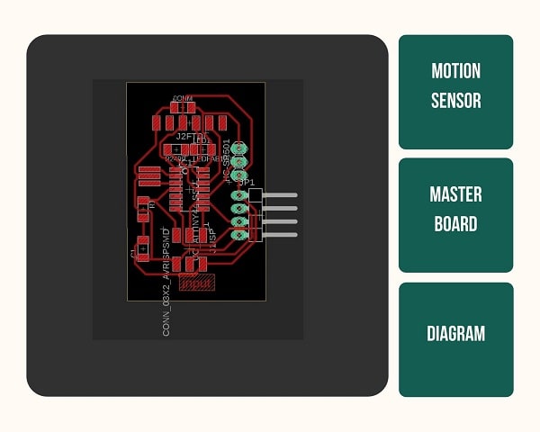
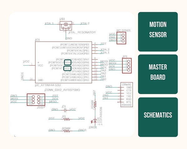
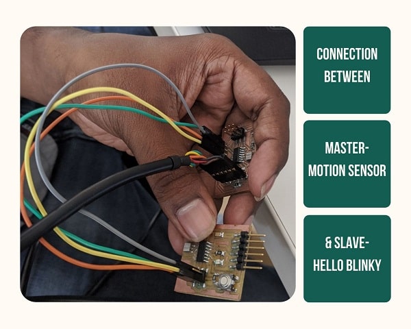
My motion sensor board from Assignment 10 was used as the Master board.

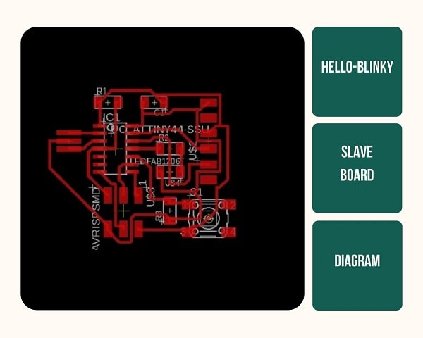
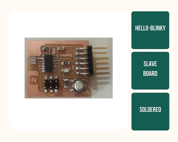
I used the Hello-Blinky Board from Assignment 7 , Electronics Design as my Slave Board
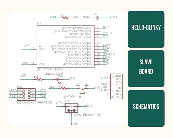
I connected the SCK, SDA, VCC and GND
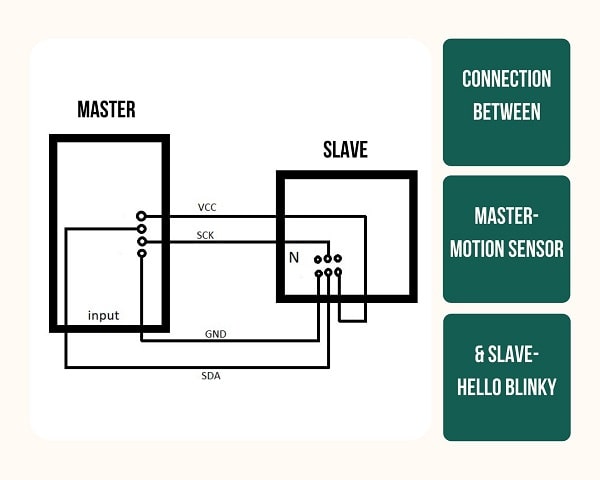
I connected the Master Node and the Slave Node using the jumper wires.
Programming
Master Program
#include <Wire.h>
#include<SoftwareSerial.h>

#define button A3
#define led1 A2
SoftwareSerial mySerial(1, 0); // RX, TX

void setup() {
  pinMode(led1, OUTPUT);

  mySerial.begin(9600);
 Wire.begin();
  pinMode(button, INPUT);
}

void loop() {
  int data;
  data = digitalRead(button);
  mySerial.println(data);

  if (data == 1)
  {
    digitalWrite(led1,HIGH);

    Wire.beginTransmission(8);
    Wire.write(1);
    Wire.endTransmission();

  }
  else {
    digitalWrite(led1, LOW);

    Wire.beginTransmission(8);
   Wire.write(0);
    Wire.endTransmission();

  }


  delay(500);
}
Slave Program
#include <Wire.h>

#define led1 1
#define led2 2

void setup() {

  Wire.begin(8);

 Wire.onReceive(receiveEvent);
  pinMode(led1, OUTPUT);
 pinMode(led2, OUTPUT);
}

void loop() {

  delay(100);
}

void receiveEvent(int howMany) {
  int x = Wire.read();

  if (x == 1)
  {

    digitalWrite(led1,  LOW);
    digitalWrite(led2,  HIGH);

  }

  if (x == 0)
  {
    digitalWrite(led1, HIGH);
   digitalWrite(led2,  LOW);

  }
}
There isn’t much change necessary for the slave code, just make sure that the address you give to the salve is the same as the one in the master.
Working
### Mistakes and Learnings
Learning I2C protocol took me some time especially with reference to my Master board, Motion sensor because instead of SDA, I opted to give it the name MOSI. It confused me.
I now realise the importance of adding Pull up resistors to boards.