6. 3D Scanning and printing
This week we learned about 3D Scanning and Printing. We had to work in detail on Fusion 360.
Objectives
- Learn about the 3D printing machines in our lab and its parameters
- Group assignment- Test the design rules for our 3D printer
- Individual assignment - Design and 3D print an object (small, few cm3, limited by printer time) that could not be made subtractively
- 3D scan an object (and optionally print it)
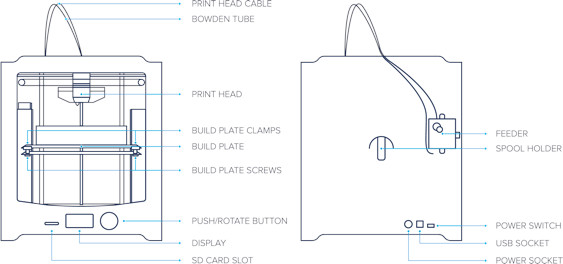
Ultimaker 2+ Parameters
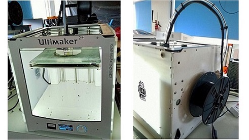
Build volume of Ultimaker 2+ is up to 223 x 223 x 305 mm (8.8 x 8.8 x 12 inches); Large build volume, yet fit any desk.
Nozzle sizes of 0.25, 0.4, 0.6 and 0.8 are available and one can switch betwen these. The standard is 0.4 mm but the option for 0.25 mm for detailed print and 0.8 mm for fast prints are also available. Calibrating the build plate level height is easy with the automatic adjustment.
Nozzle Temperature is maintained at 210 degree celsius. 35 watt heater cartridge that heats the nozzle in under a minute and allows for fast prints.
Plate Temperature is maintained at 50 degree celsius
Printhead travel speed is 300mm/s
Build speed can be upto 24 cubic mm/s
Layer Resolution Range is from 600 microns to 20 microns
Open Filament System can print with any 2.85 mm material
A 3D Print Layout
Shells: The walls of the print that are exposed to the outside of the model. These are the number of layers on the outside of a print. In FDM printers, shells are always the first areas to be printed per layer.
Several shell related design considerations for FDM printing are:
- Strength can be added by increasing shells thickness. This provides a slightly more robust print without having to increase the amount of material used for infill.
- If a print is to be finished by sanding or chemical smoothing increasing shell thickness is required because such post-processing methods reduce the thickness of the surface of the model.
- Any increase in the number of shells also increase the amount of time and material required to print the model increasing overall part cost
- Shells typically consist of a specified number of nozzle diameters therefore it is good to design shells to be a multiple of nozzle diameter to prevent voids from being formed.
Bottom layers (a type of shell): The part of the print that is exposed to the outside of the model, facing the build plate
Top layers (a type of shell): The parts of the print that is exposed to the outside of the model, facing upwards, towards the nozzle. Typically this surface will have the best surface finish
Infill: The internal structure of the print
Infill percentage: The strength of a design is directly related to infill percentage. A part with 50% infill compared to 25% is typically 25% stronger. FDM prints are typically printed with a low density infill. Most FDM slicer programs will by default print parts with a 18% - 20% infill which is perfectly adequate for the majority of 3D printing applications. This allows for faster and more affordable prints.
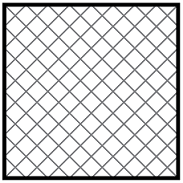
Infill Geometry:
- Rectangular: The most common fill but it really has no real benefit over some of the others. It is simple and often a default in printing software.
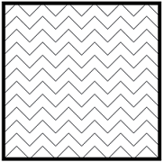
- Wiggle: Only for a part that can twist and needs a little bit of flexibility to it. This shape offers the least amount of rigidity and is otherwise useless.
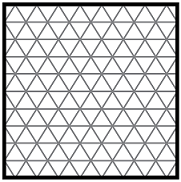
- Triangular: This shape offers great strength and high lateral loads, therefore very useful. This is good for increased wall strength or longer slender structures like bridges and roof trusses.
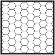
4. Hexagon aka the honeycomb: This provides the best infill for strength vs material used. This shape is the most efficient infill and fastest to print, the goto infill for most things. It saves material, time, energy and offers high strength. This is infact a good example of bio-mimicing. This is why the honey bees home is formed of hexagons. Wax is very costly to make and economically bee’s just want to make tubes with as little wax as possible to house larva, honey and what-not. Nature takes advantage of this all over the place, it’s both efficient, elegant and mathematically beautiful. This naturally occurring phenomenon is really just circles pressed together to form a tessellation. Honey bee’s are not aware of what they are building and are really only trying to form tubes that their bodies can fit into. As they build more and more of these tubes in a closed space they press together and form hexagons. It’s the only outcome or shape that could occur from this which is why it is all over the place in nature.
Group Assignment
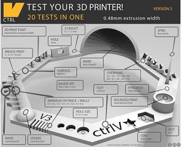
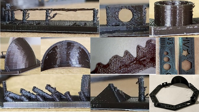
We tested using the file “Test your 3D printer! v3” by ctrlV on Thingiverse. We used Cura to set up the print file and generate a gcode that can be used in the 3D-printer. We could only manage the 0.4mm nozzle in ultimaker 2+.
Preparing our file in Cura
We opened the 3d model that is saved as a stl format. The model could be previewed using zooming, panning and rotating view. It can be spinned on its x, y, z axes. Any model can be spinned with the rotate tool to give it an optimised orientation for 3D printing and we selected our model to sit on its base. The scale tool allowed us to resize our model in multiple ways. We could go for the maximum size possible or could change its size in millimeters or as a percentage of the original model or we could use the mouse to scale up or down. We changed the print job settings.
Printer: Ultimaker 2+ Nozzle: 0.4 mm Material: PLA Profile: Infill: Cura is an open source 3D printer slicing application.
Individual Assignment
Additive vs Subtractive Manufacturing

Subtractive Process
Subtractive manufacturing process involves removing sections of a material by machining or cutting it away. Creating a Sculpture from wood is Subtractive Process.
Additive Process
Additive manufacturing process is a process that adds successive layers of material to create an object. Creating a terracotta sculpture by adding soil part by part is Additive Process.
Research
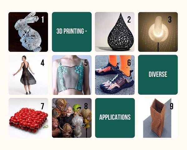
- Bunny mathematical sculpture
- Contemporary Sculpture
- Geometric Lamps
- 3D Printed clothes
- Miranda Marquez
- Fused Footwear
- Dinara Kasko
- Rick Baker
9.Ceramic Constellation
Parametric equation
Links:
All3DP
Instructables
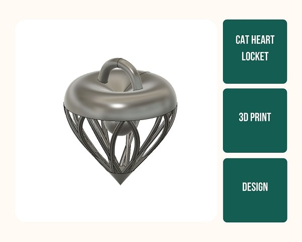
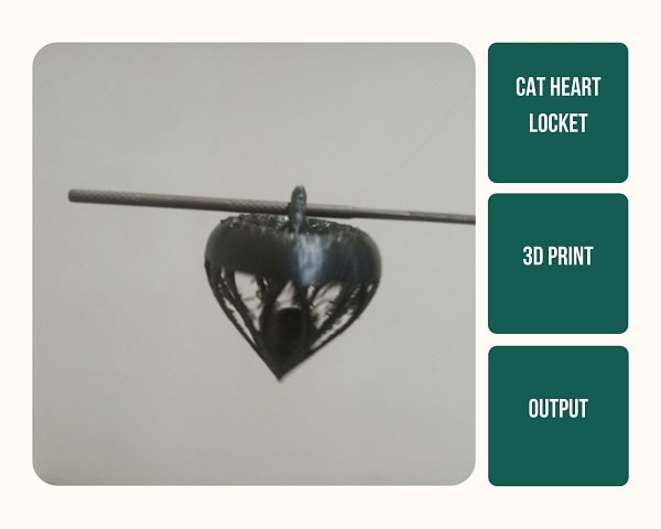
3D Print-Heart Pendant
I initially designed a dovetail joint, but as it turns out there are machines that can create this “impossible” joint. I decided to make a Pendant for my Cat’s Collar with a Ball inside it.
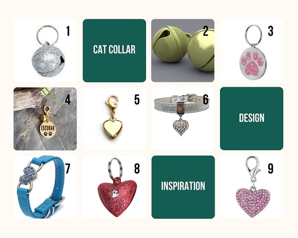
I made a heart shaped pendant and test printed in a bigger scale.
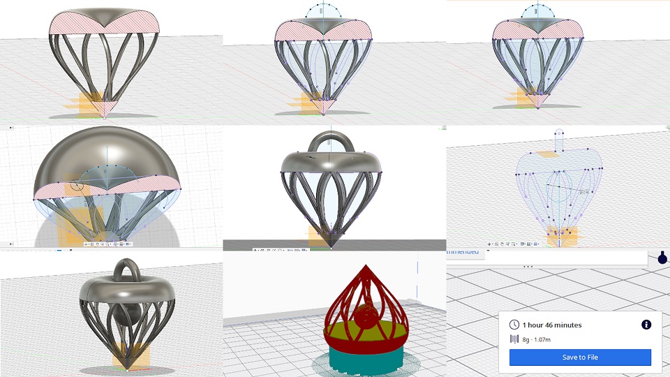
The heart shaped pendant has a circular ball inside of it which can be viewed from outside through the “jaalis” in the outside. The ball can move inside the pendant.
It is impossible to make such a design using traditional subtractive methods because the inside of the pendant cannot be subtracted away and yet isolate the circle cannot be isolate.
But this is easily possible using a 3D printer as it is building layer by layer.
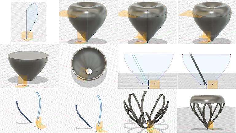
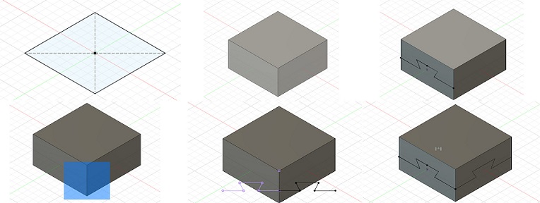
Image 1: Under Sketch menu=> Create Sketch, I chose a plane.
Select line tool, start it at the origin. Click my mouse up, and click again to stop the line. Press escape.
I pressed D and dimensioned the line to 27mm.
I clicked the spline tool and started from one end of the line by clicking once. I clicked several times on the way to add control points and ended on the top of the line and clicked on the hand to finish the spline. The tangents in the control points on the path can be adjusted to get a nice smooth curve that looks like half a 2D heart.
3D scan a body and print it
Our Leo scanner is yet to come and since we didn’t have any other option to scan we tried photogrammetry.
We took lots of photos of a tiny tree of life and downloaded meshroom to edit it. But uploading each image in its true size was taking way too long, so we discarded it.
So our instructors told us to do the scanning after two weeks when Leo reaches its home here.
Research
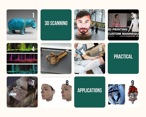
1. William the Hippo
2. As We Are - Matthew Mohr 2017
3. 3D printed life like mannequins
4. Scanlab Projects
5. Preserving artefacts
6. Prosthetics
7. Crime Scene Reconstruction
8. Plastic Surgery
9. Reverse Engineering
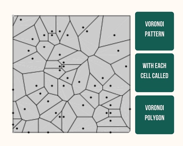
Voronoi Pattern
My aim is to get the 3D scanned output in a voronoi patterned image.
3D Scan myself
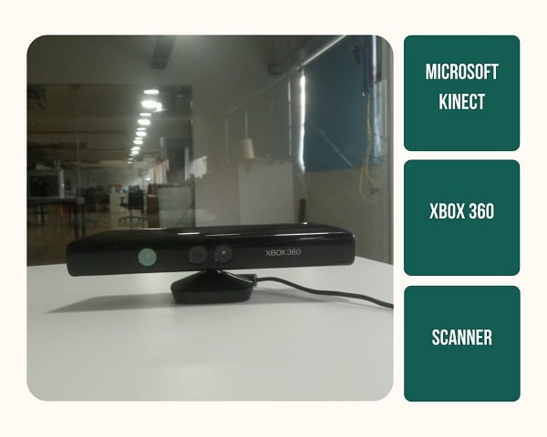
For 3D scanning, I first tried with Leo Artec a 3D scanner which our lab recently aquired. It is a handheld scanner and it was fun to scan with it and to be scanned by it. However, due to a technical issue we are not able to get the output of this high quality scan. So I ended up using Microsoft Kinect XBOX 360.
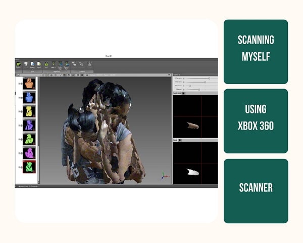
Step 1: I downloaded the Kscan 3D setup, installed it and set it up for scanning.
Step 2: Next I stood in front of it, so my upper body would be in the scan area of the device. I positioned the focus on myself by changing x,y and z coordinates. Then I marked 20 spots in a 360 degree angle from where I was standing so I would move in correct angles. Next I started the scan and I rotated 360 degrees. I took 20 images from different angles.
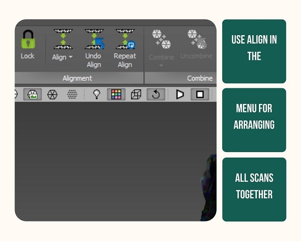
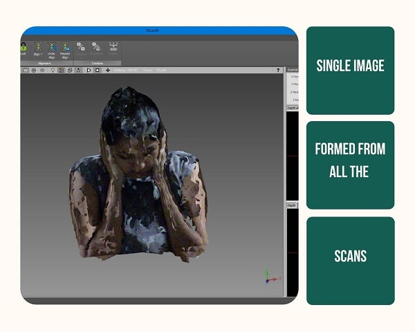
Step 3: Click “Align” to arrange the different scans into one complete scan.
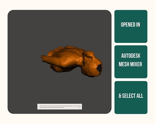
Step 4: I exported this to mesh mixer, selected all.
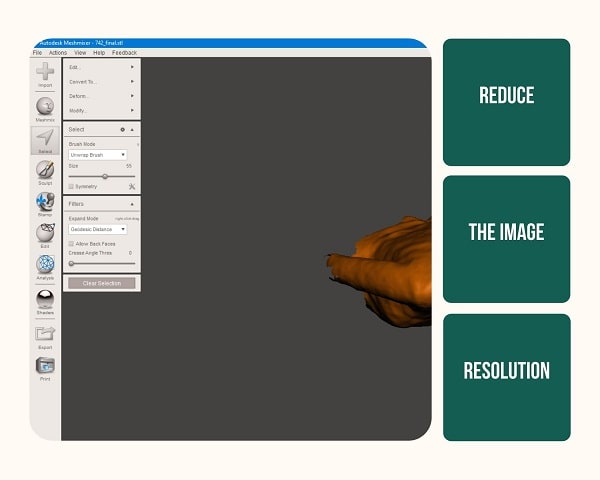
Step 5: A pop up box opened up when I selected all on which I could find Edit–Reduce
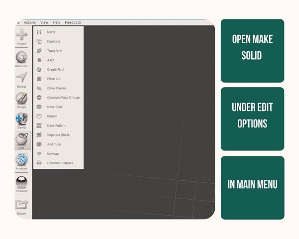
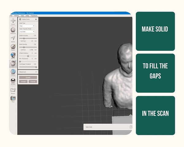
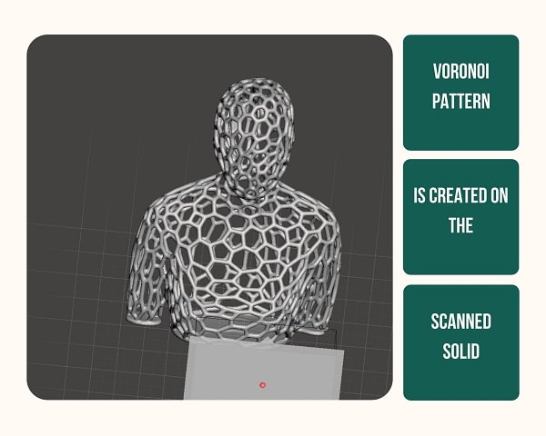
Step 6: I wanted to make it into a solid to fill the gaps, so I pressed the “Edit” and chose “Make Solid” and changed the settings.
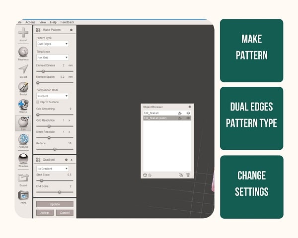
Step 7: To make the voronoi patten, I clicked on the main “Edit” menu option then the “Make Pattern” I chose dual edges and increased
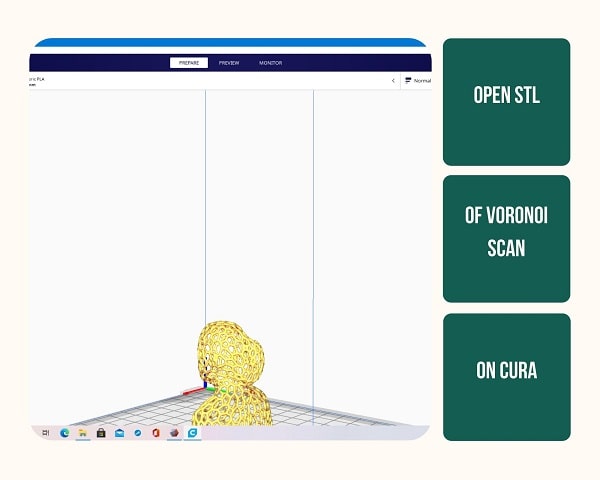
Step 8: I got the voronoi patterned output which I exported as an .stl file
Step 9: I opened the .stl file in Cura
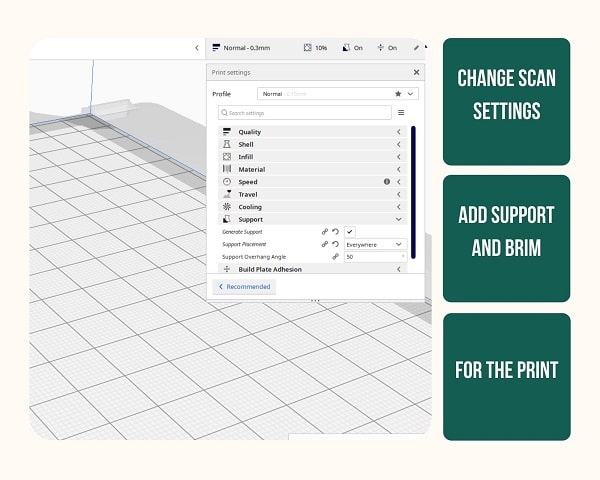
Step 10: I changed the print settings, infill percentage, gave support and added brim.
Step 11: The file is saved into the 3D printer SD Card as .stl file and gave for printing
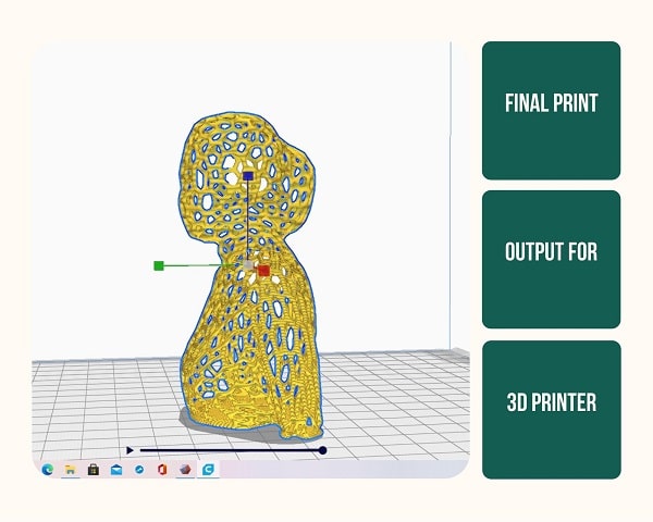
The file is ready to be 3d printed
Discarded Individual Assignment
Dovetail Joint
Files
For my files click here.