3. Computer Aided design
Objectives
The objective for this week is to model (raster, vector, 2D, 3D, render, animate, simulate, …) a possible final project, compress the images and videos, and post it on my class page.
Files and Tools
Files
Find all my files here:
Tools used
Inkscape
GIMP
Autodesk Fusion 360
Research
To learn more about raster vs vector files -Shutterstock
Very easy explanation - IMX Video&Design Channel
To understand Raster vs Vector - Fastprint
Channel on YouTube to learn more about GIMP - Tutorials4view
Tutorial ON GIMP - Davies media design
Fusion 360 basics from Product design online channel
How to make a box in Fusion 360 by Lars Christensen
Individual Assignment
Raster and Vector
Both Vectors and Rasters are made of pixels. Vector graphics have anchor points and they are connected by formulas and can change shape according to the connections. Both look the same when scaled down.
Raster Graphics have a limited amount of pixels and gets blurry when scaled, Raster graphics are large files, has millions of elements and increases the size on scaling up, Rsater graphics are used for detailed images like photos. All the photos taken on a mobile phone or camera are raster files.
Vector Graphics are recreated mathematically and the scaling will not affect their quality, Vector files are usually small and has very few elements, they stay the same inspite of the scaling, Vector graphics are used for less detailed images like logos, texts, illustrations etc. Vector images are created using softwares.
Example
Vector creation and editing using Inkscape
I downloaded inkscape, a vector editing software, rather than illustrator or coral draw because it is free. I am also planning to download and learn Free CAD.
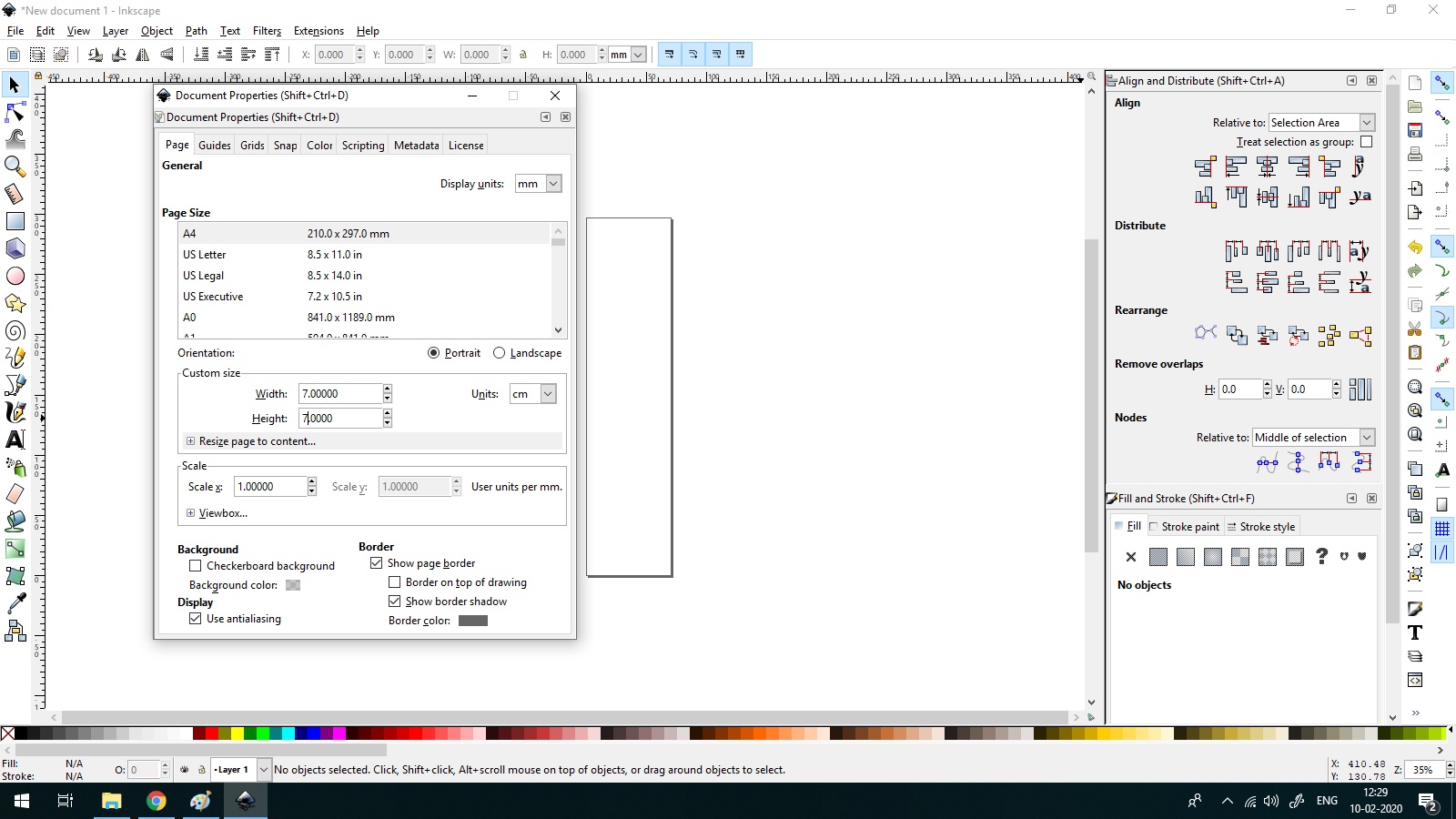
“To start with I learned document properties. I changed to 10 cm* 10 cm square for my project”
“Cntrl with left button can increase or decrease selection”
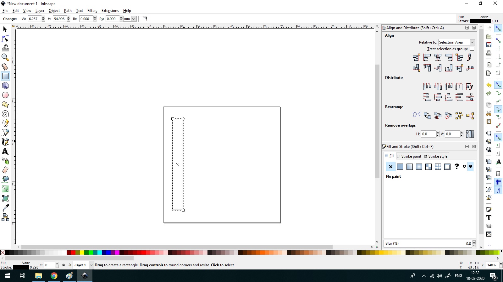
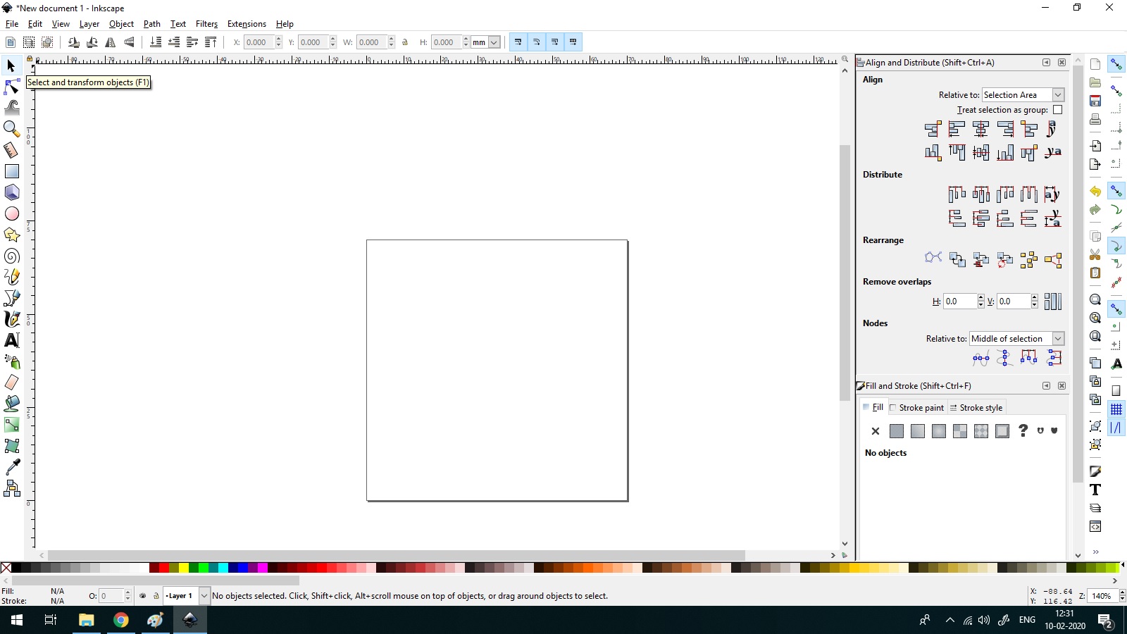
“To draw Rectangle”
“To change alignment when I join two shapes”
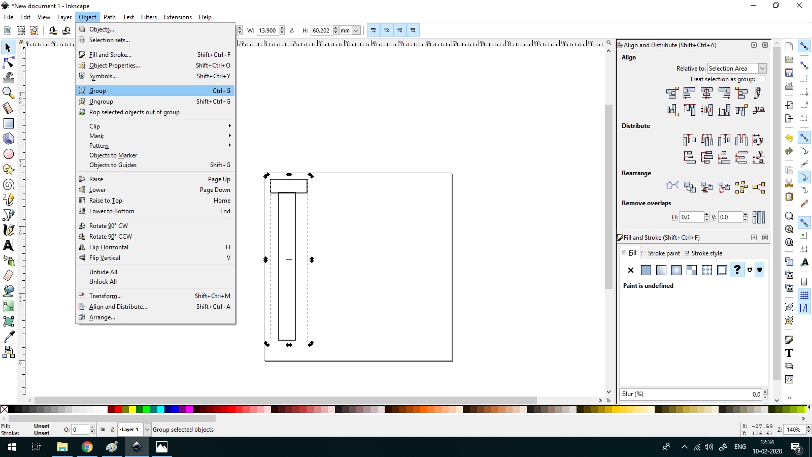
“Group multiple shapes together”
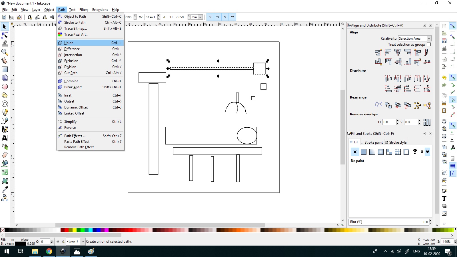
” Boolean operation Union”
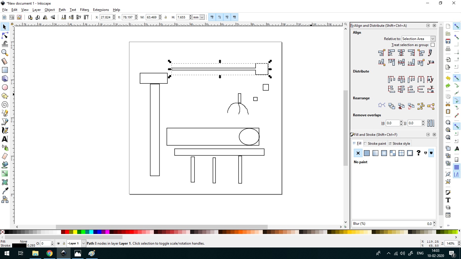
” Unioned!!!”
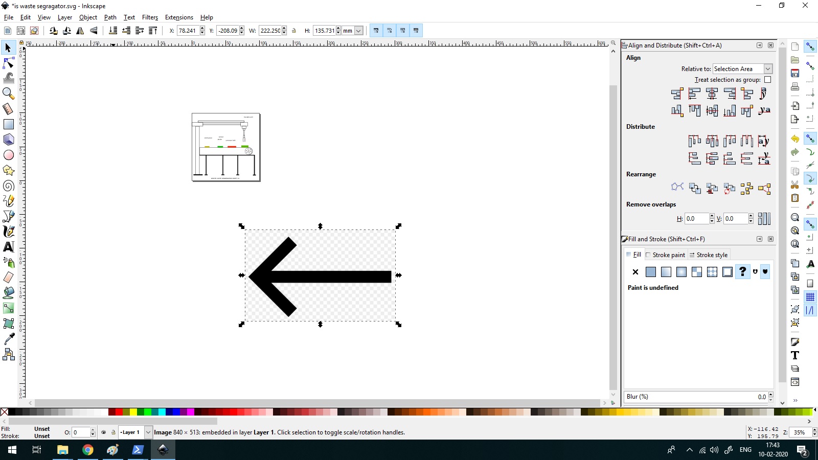
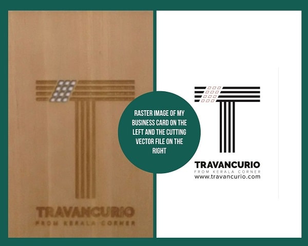
“To convert the raster image of Arrow to vector image of Arrow “
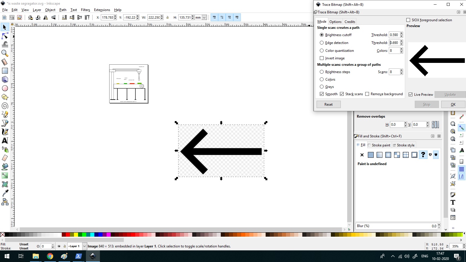
“The process”
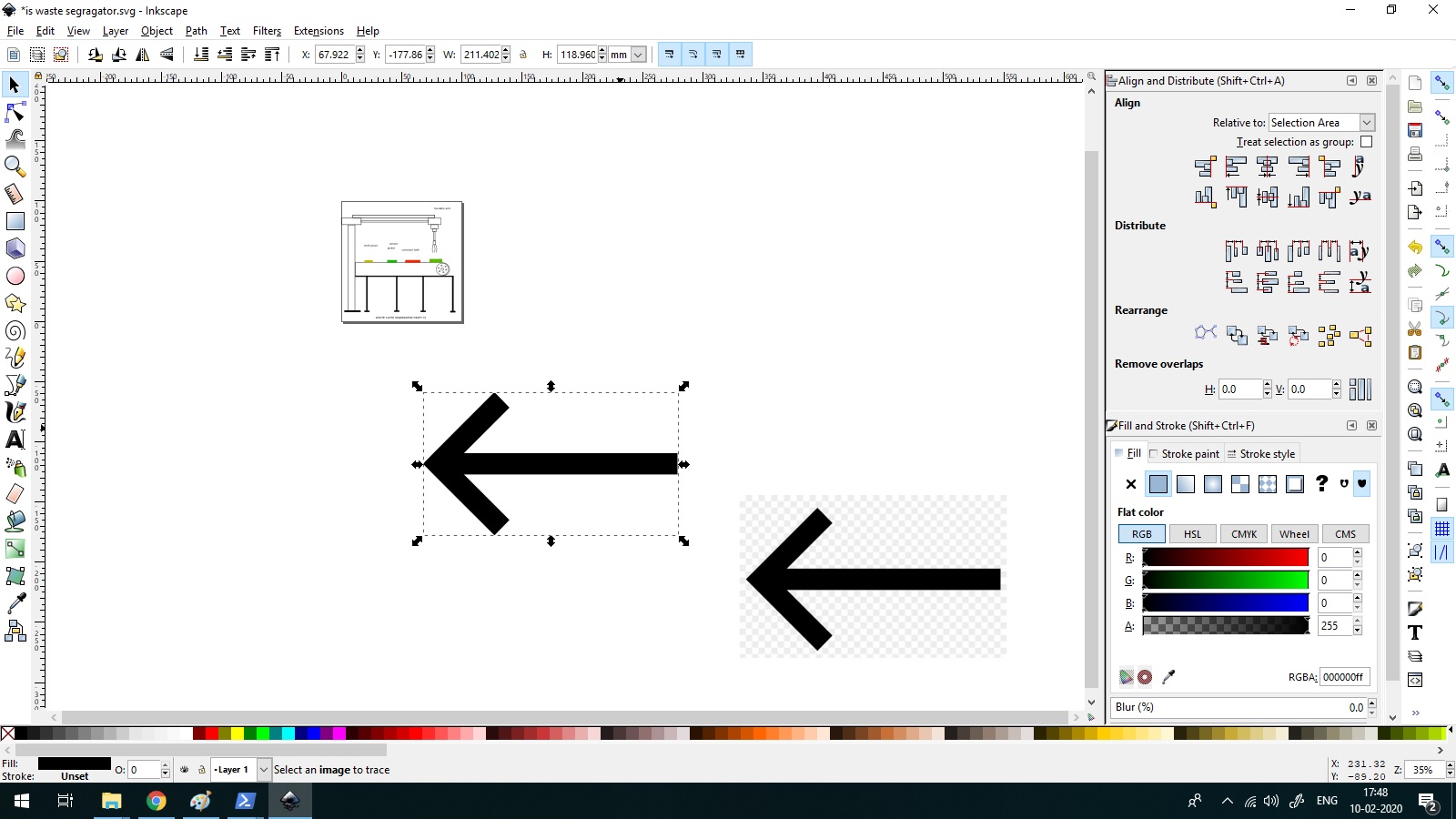
“Vectored!!!”
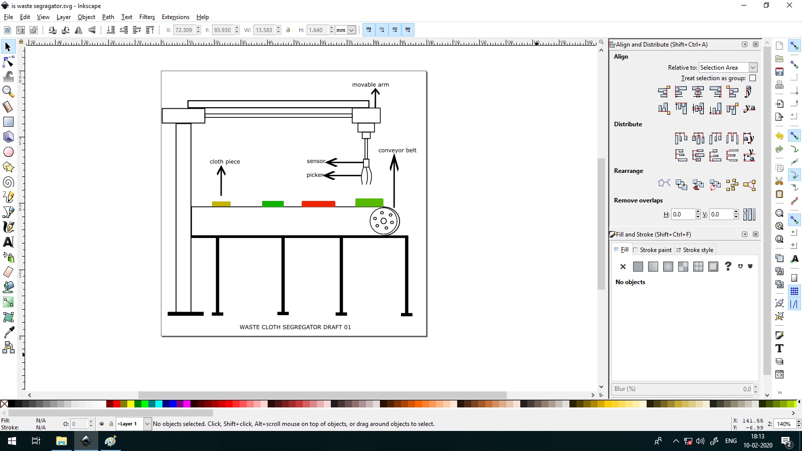
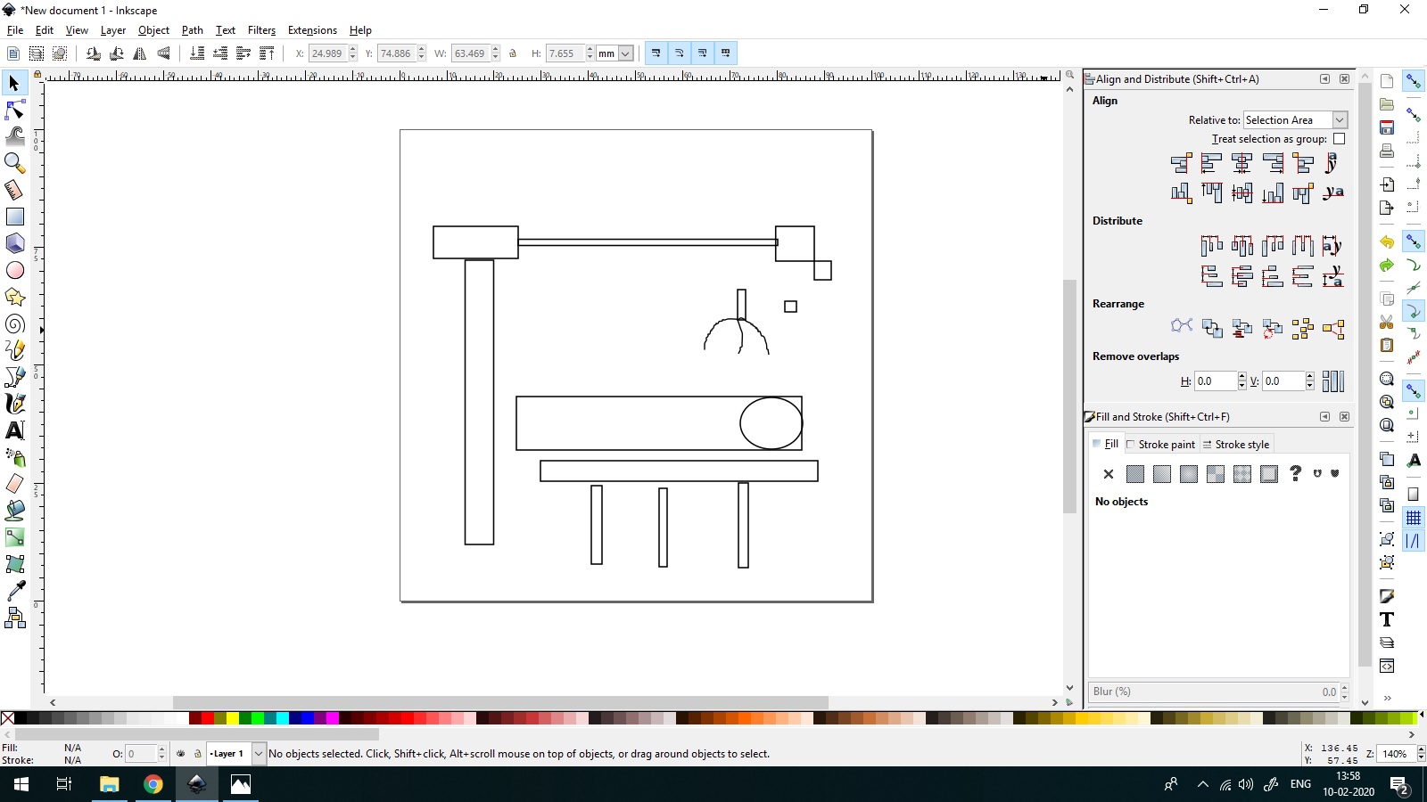
“Final project screenshot of inkscape”
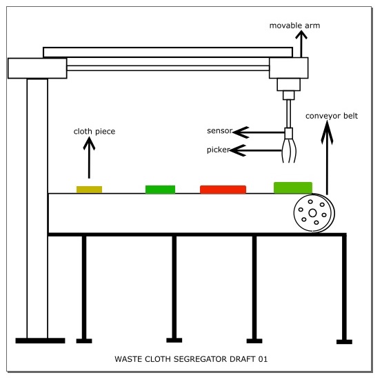
“My final Project - Draft 01”
Learning Boolean operations
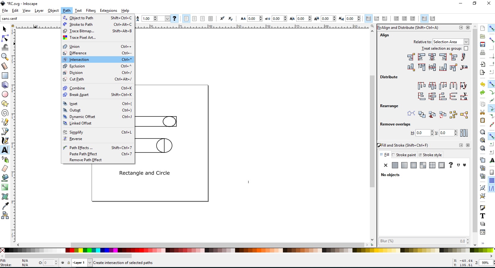
“Boolean operations can be found under Path in the main menu”
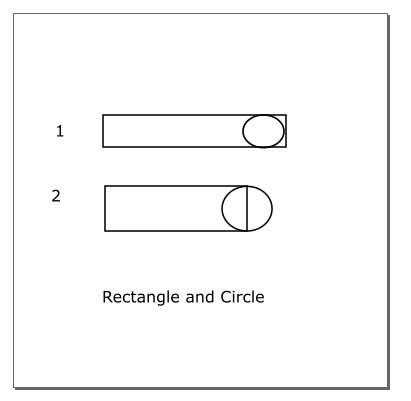
“A Rectangle and circle drawn in two forms”
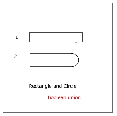
“Boolean operation Union of two Rectangle circle combinations”
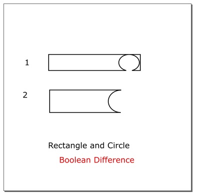
“Boolean operation Difference of two Rectangle circle combinations”
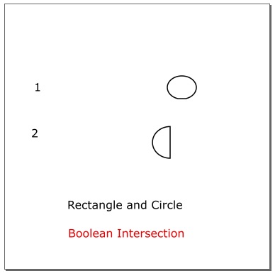
“Boolean operation Intersection of two Rectangle circle combinations”
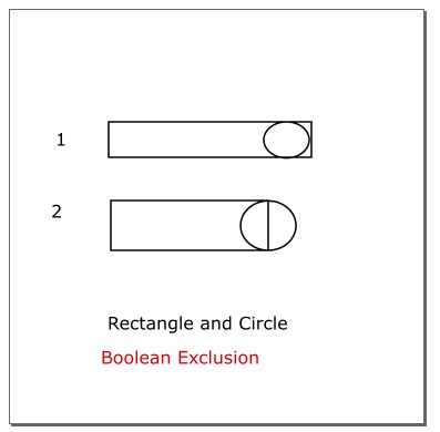
“Boolean operation Exclusion of two Rectangle circle combinations”
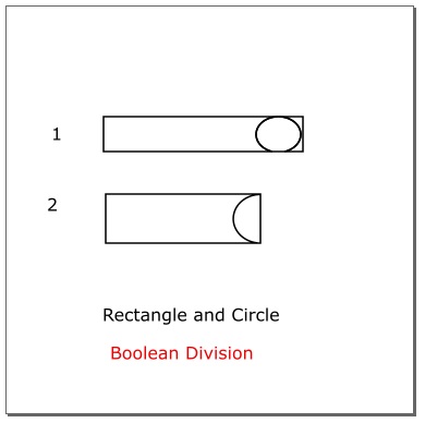
“Boolean operation Division of two Rectangle circle combinations”
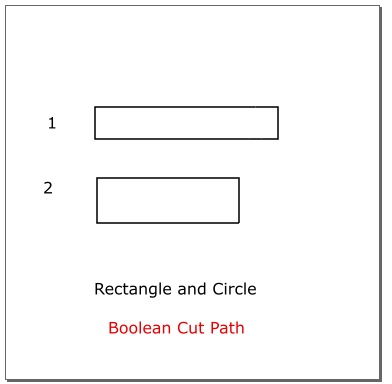
“Operation Cut Path of two Rectangle circle combinations”
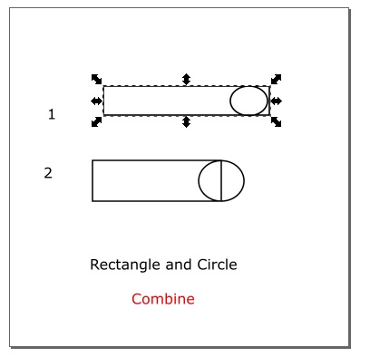
“Operation combine of two Rectangle circle combinations”
What I liked about Inkscape
I liked that it was easy to learn, file is really small, so it was fast to download . I especially liked the boolean operations and trace bitmap. I was able to trace my card from the image.
What I didn’t like about inkscape
It is not very user friendly in certain areas - I was unable to combine a Rectangle with a Circle when the circle was placed inside (near the edge of the rectangle). None of the Boolean operations worked in this case. However I rectified it by placing the centre of the circle on the edge of the rectangle
Raster Editing using GIMP - GNU Image Manipulation Program
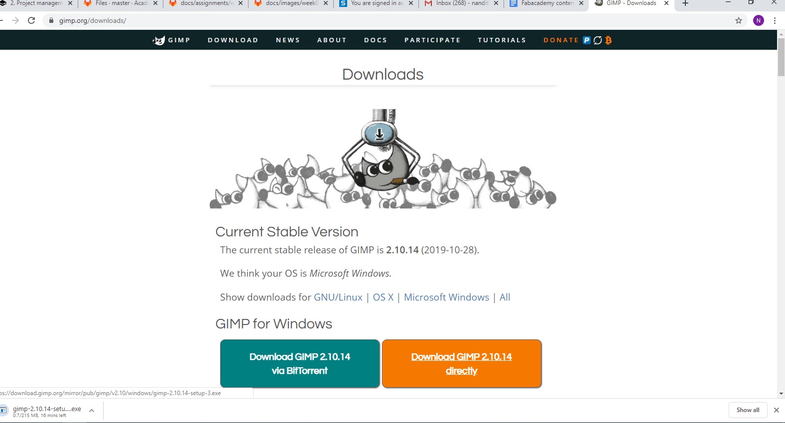
GIMP is a free and open source project that is set up to allow anyone in the world to view, edit, and make changes to the images then submit back to the project.
I downloaded GIMP for windows directly.
Import new photo to GIMP
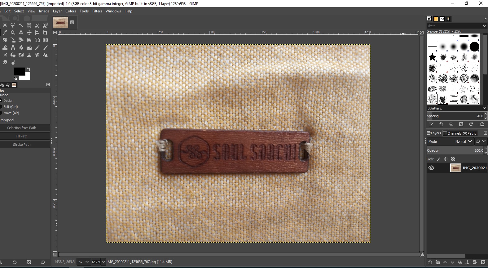
Remove Background
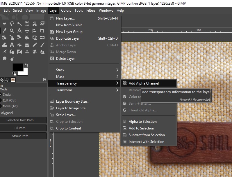
“Go to Layer-Transparency- Add Alpha channel to Add Transparency”
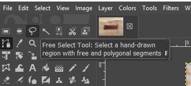
“Free Select Tool— Click and drag on the portion to be cut”
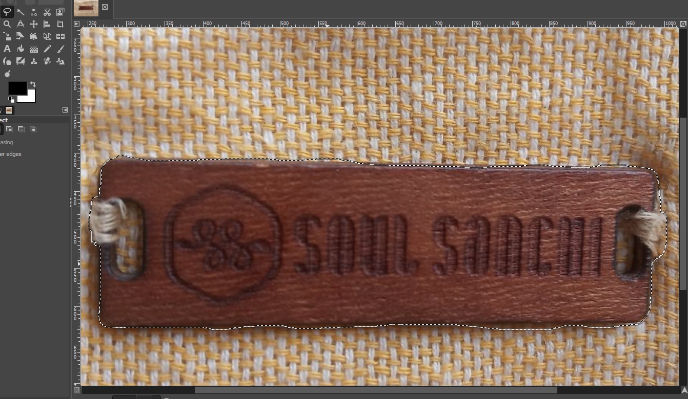
“Slide it all the way to the starting point and click it Click”
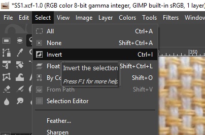
“Select>> invert”
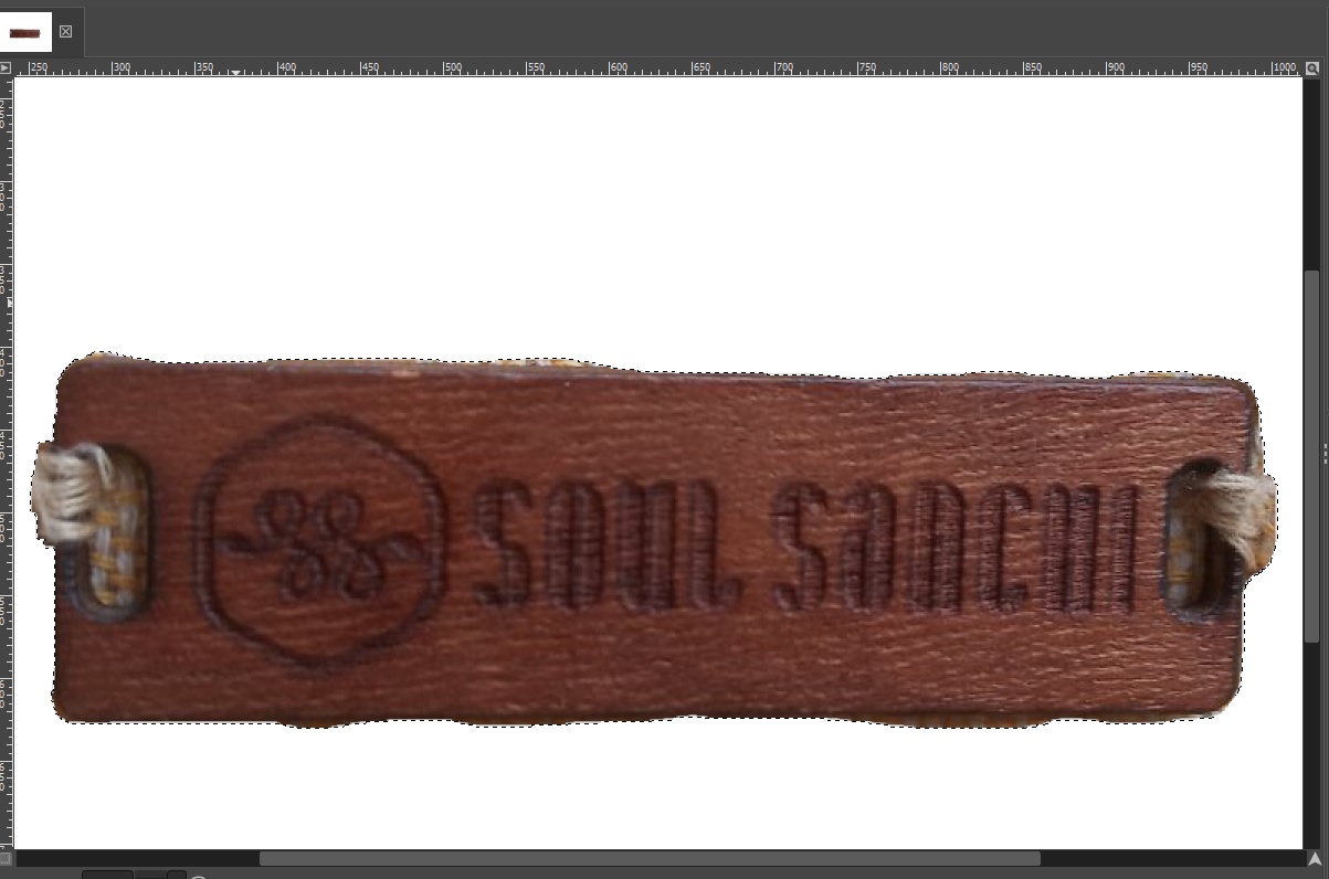
“Cntrl+x to remove the background”
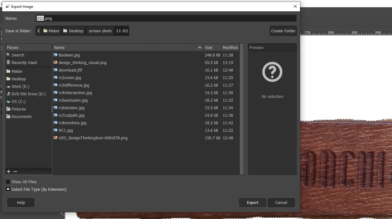
“Save it as .png to preserve transparency And Export”
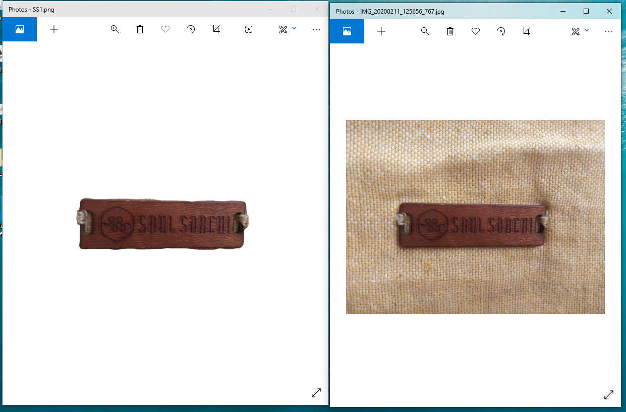
“Compare original and final cut”
Added one image to another
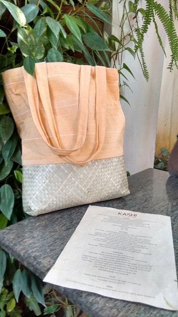
“No logo in this photo”
“Removed logo from this photo”
“Added to the original photo”
3D Designing - Autodesk Fusion 360
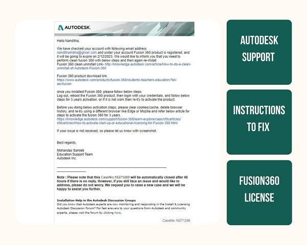
I learned fusion 360 because it is free. First I downloaded it from the Autodesk website and tried the free trial version. For some reason, I wasn’t able to get the free trial even after I registered with my Fablab credentials. I contacted the customer care who promptly gave me advise to fix the problem.
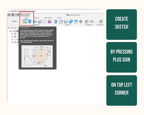
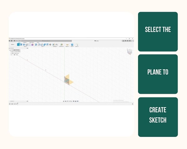
Step 1: First I opened the Fusion 360 and pressed on Create Sketch to start drawing. Next the plane on which I drew was selected by clicking on the axis given at the origin. I chose the bottom one and to view this from top I pressed on TOP of the square that is on the right corner.
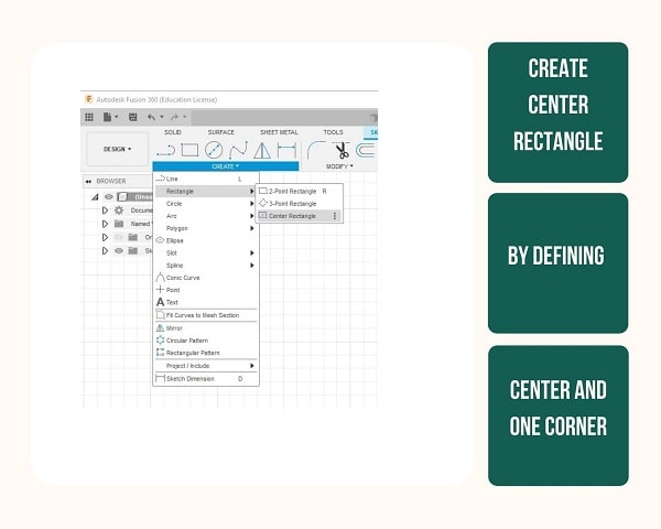
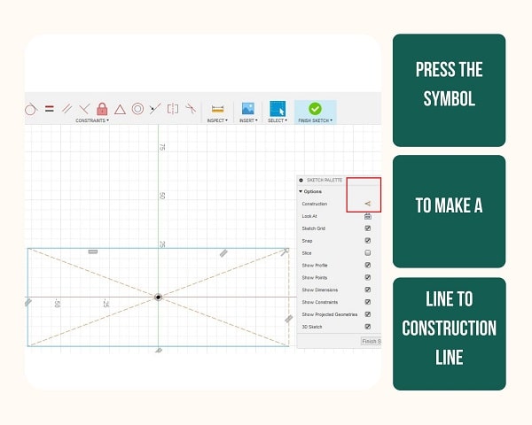
Step 2: As I have to draw a sketch I pressed create sketch on the main menu and used the Center Rectangle tool. In this, I had to click where I had to position where I want the center to be and the one corner of the rectangle. Then a box popped up on the right called sketch palette. As this first rectangle is not something on which I want to build on but rather a general rectangle that would hel me position these things, I made it into a construction line by pressing the construction symbol after clicking each side of the rectangle. Then each line transformed to dotted lines than a rather straight line.
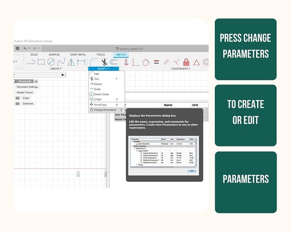
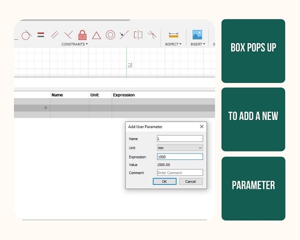
Step 3: Next I want to give the dimensions of the rectangle as well as the model I would be making. For this I took Change Parameters from the mian menu and added the name and dimension of each parameter I want to add in the popup box.
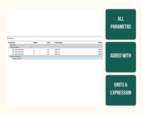
Step 4: Next I dimensioned each side by clicking on the line and pressing D. Then a dimension rectangle appeared on which I could enter the dimension by pressing the already given parameter name.
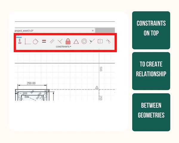
Next I learned about constraints and realised that each geometry I make can be constrained with another. A line and another line can be made equal, which means, whenever the dimension of one line is changed the other changes accordingly. If Ipress perpendicular constraint on two lines then one line will always be in 90 degree with the other. I went on creating other lines and given them dimensions and constrained them with each other.
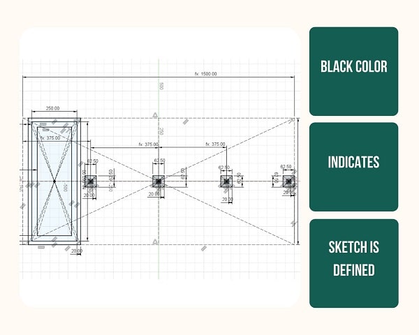
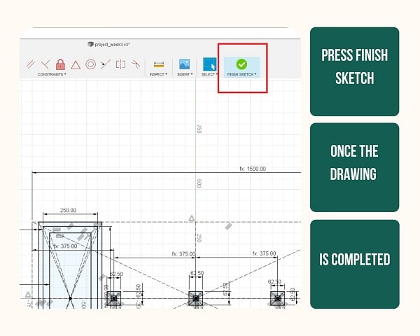
Step 5: Once all the lines are given dimensions and all the lines were constrained, the colour of the lines changed from blue to black which shows it is fully defined. Next I pressed the finish sketch on the top right corner of the menu so I can finish this sketch and exit the diagram.
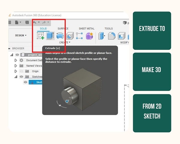
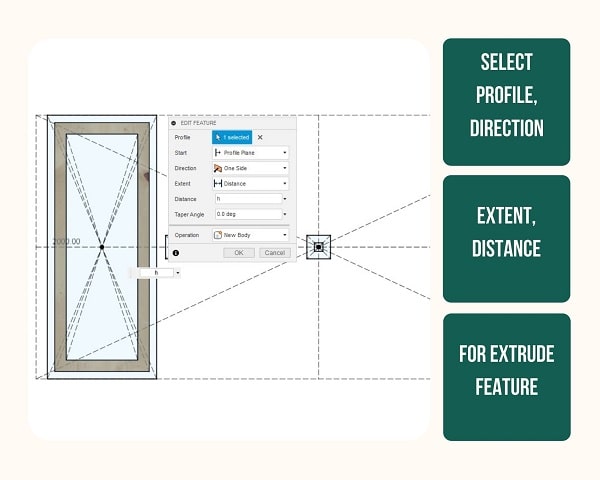
Step 6: To make the 2D sketch to a 3D I used a tool called Extrude. Then a box popped up and it allowed me to choose the part of the sketch I wanted to extrude and to what directions for how much distance. I tried it out by changing the angles as well. I realised that it works only with closed figures. When I gave the correct figure and distance of the base of the pillar of the waste segregator it magically appeared in 3D. I realised I was making each one into a new body. It was fun to create! I went on creating the bottom parts for this I had to go back to the initial sketch and added further squares(how i went back and forth is explained below) to extrude them also as new bodies.
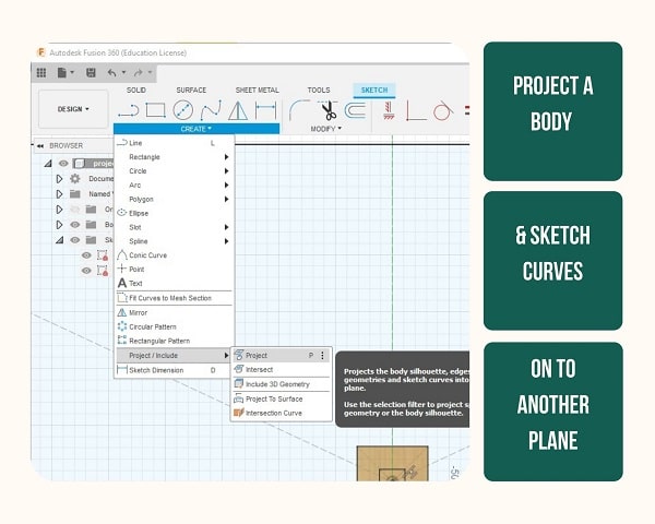
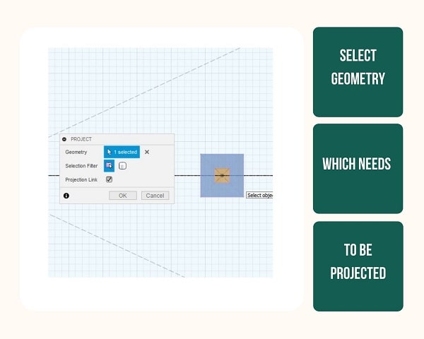
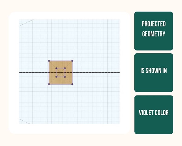
Step 7: To create a sketch a geometry based on an already drawn geometry was very confusing to me at first. I went through a tutorial to realise that it is possible to project the shape of one 3D body on to a plane thus making it easy to understand the shape and dimension of the body from the plane.
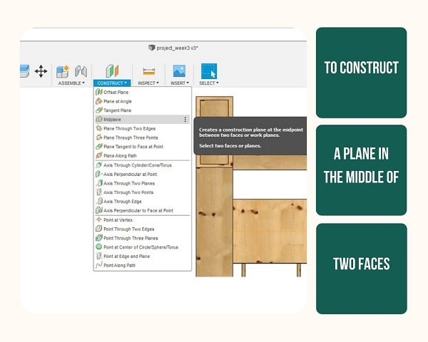
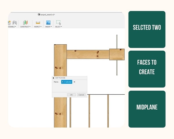
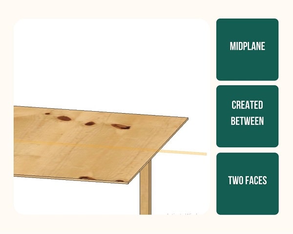
Step 8: To create the conveyor belt in the middle of the base I had to first find the middle, for this I used Midplane feature and selected the two faces of the base. Then a plane was formed in the middle on which I could make a cross section of the conveyor belt and I could extrude it to both sides.
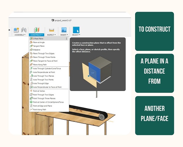
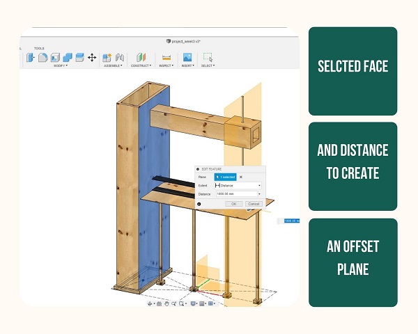
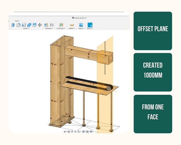
Step 9: I had to make the movable arm in such a way that it would be in the middle of the base and conveyor belt at a distance from the pillar. For this I craeted an Offset plane at 1000 mm from the pillar. Then I projected all the geometry on to it and then drew the middle portion of the arm. Then I extruded it to both sides.
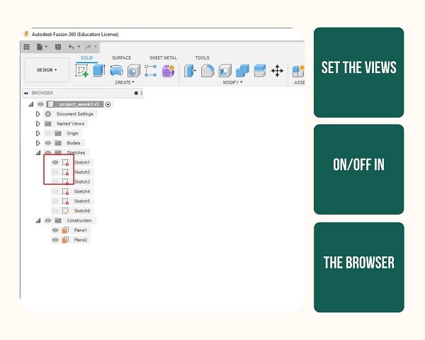
Step 10: View in the browser on the left side of the window gives all the sketches and bodies and each has an eye on its left. On pressing this I could make the corresponding sketch/Body/plane visible or hide it.
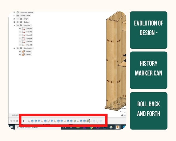
Step 11: One of the best features in Fusion 360 seems to be the History Marker. Every step that I did was saved and I could move back by clicking on the corresponding icon in the history menu given underneath. I could edit by pressing Roll History Marker here and Edit sketch OR Edit feature corrsponding to what I was doing then.
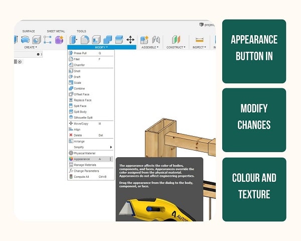
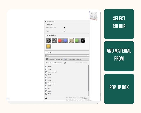
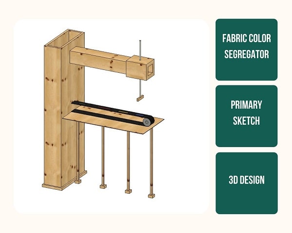
Step 12:Once I created all the bodies I wanted to make all of it look realistic. To change the appearance of each of the body, I could easily select from the given list and chose the material and the color, then drang and drop it to the body or face of the body. The library had various materials including metals(steel polished, iron matte etc), various types of wood, fabric etc
Final Model
Mistakes and Learnings
Inkscape
I forgot to keep saving throughout the progress and lost a chunk of work due to power shut down.
It took me a while to get the hang of Boolean operations.
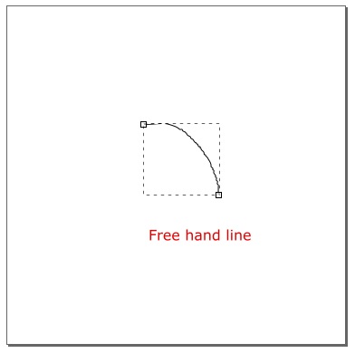
I learned three ways to draw a curve.
1. Using Free hand lines
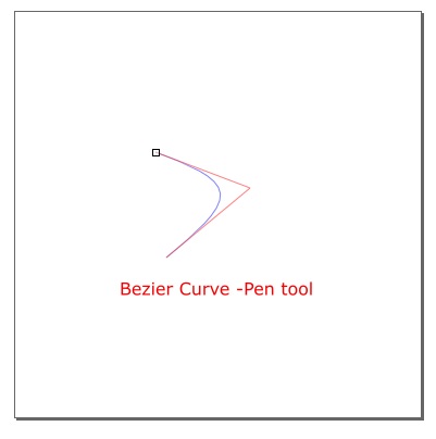
- Using Bezier curves aka pen tool and adjusting the paths. To draw a curve, I just had to click and drag from one end to another. From the second position I moved the cursor to the next end point. This forms a curve.
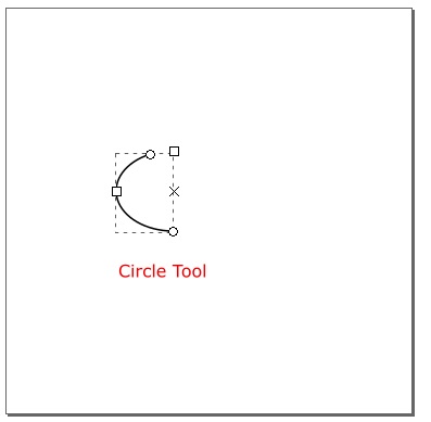
- Using circle tool and dragging the points inside of the circle only to the required curve shape
Fusion 360
It was a big learning curve to learn 3D. It was a really hard task for me to do it. I had absolutely no background in 3D and it took several tutorials and help from my instructor Jogin and my lab mate Anooj to finish my work.
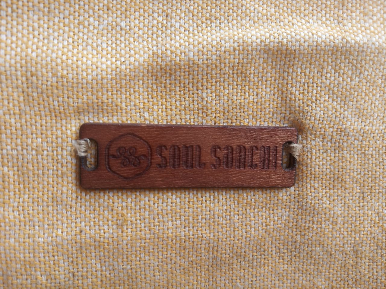
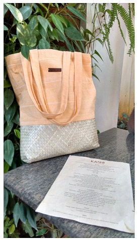
What made me proud
I wanted to add the logo to my bag for a long time, for simple things like this I always depend on my designers. It is really hard to convey what I want, I’m really happy that I was able to do this own my on. Learning 3D made me incredibly proud as I’m still able to learn it at this age.