Week 21
Project Development
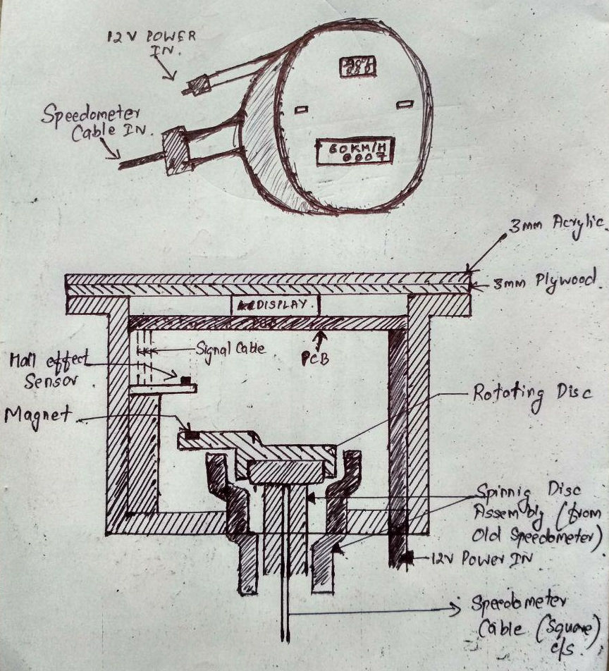
The project development started during the Networking and Communication week when the board was designed along with the main housing for the speedometer. Below is the sketch developed during that week.
The integration of the electronics into the housing was partially taken care in the design and the integration into the morocycle remained to be done. The integration was to be first completed followed by making the digital hall effect sensor to work by programming the MCU. The final presentation to neil, was scheduled on the early hours (02.30 IST) of 19.06.2018 before which the presentation slide and presentation video was also to be made. I have 12 days left to complete the project and its documentation. Also, the weekly assignments have to be submitted for global evaluation before 11th.
I plan to begin integrating the housing, and testing the rotating disc on the motorcycle by making test ride. With the board, main housing and the rotating disc in hand, I plan to follow it with learning to use interrupts of the MCU and then to programme the board. All the procurement were already made and the sensors are at hand. The code for LCD display was already working, and the interrupt function was to be integrated into the code. Apart fom this, the magnetometer sensor have to be made working.
After the MCU start to accept the interrupt from the hall effect sensor and display the result onto the LCD, i will have to finalise the design by cutting acrylic.
I will do the motorcyle integration during the day time and spend the nights for learning to use interrupts. These two things has to be finished in the first 6 days along with submitting the weekly assignments. Weekly assignments have to be given priority till 11th and then project has to be finalised. The code should be working before 14th after which the top covers will be designed and fabricated. The integration to the motorcycle should be made latest by 16th. The video has to be recorded during the process itself. Presentation slide can be finalised on 17th.
Mechanical Design
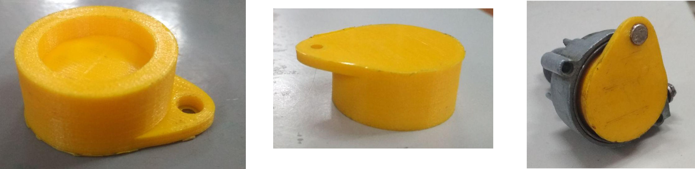
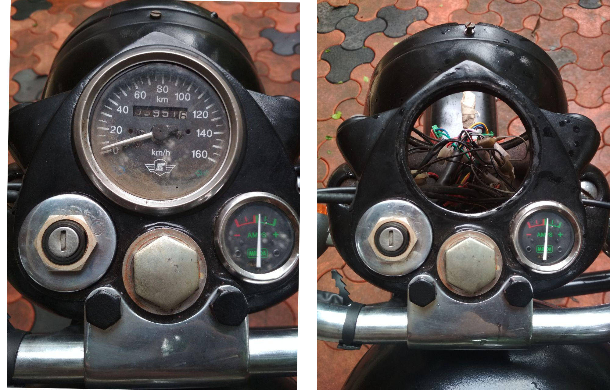
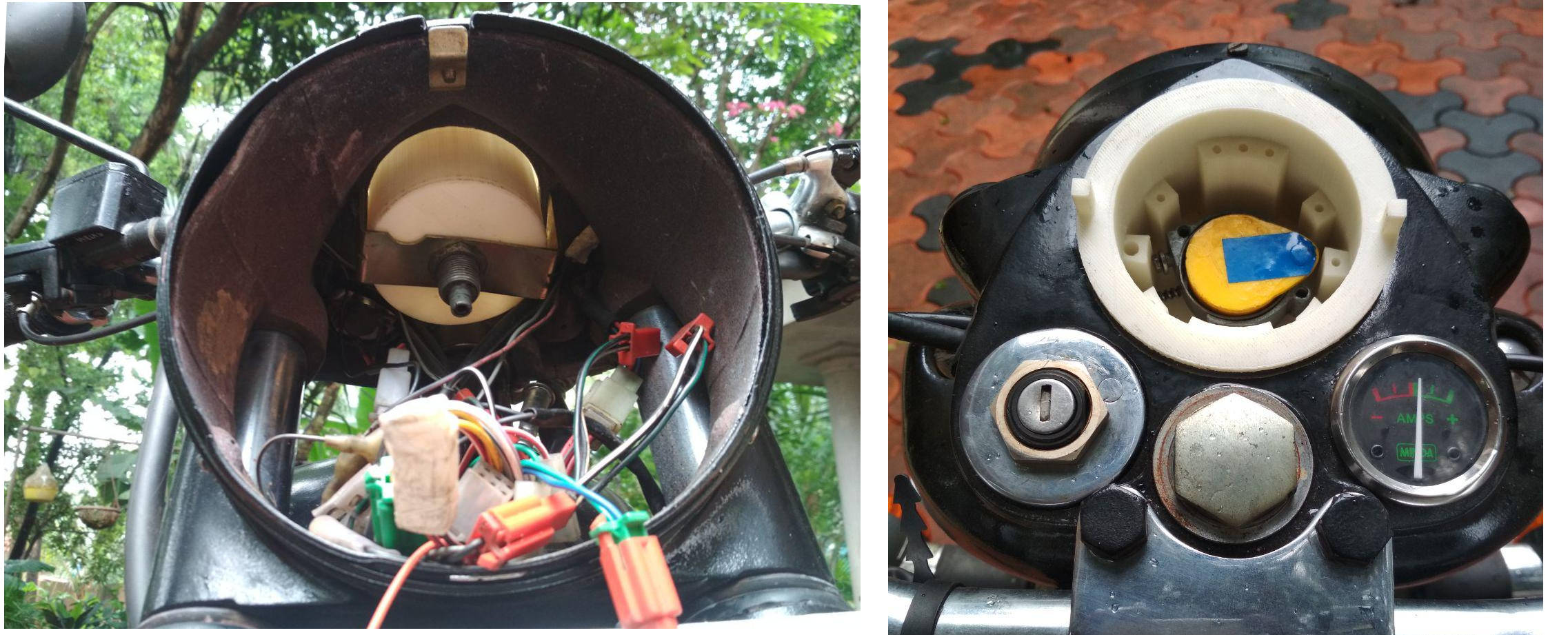
The below image on the left shows the rotating assembly used from the old analog speedometer. The speedometer cable can also be seen which when rotates, rotate the shiny disc on the left side of the image.
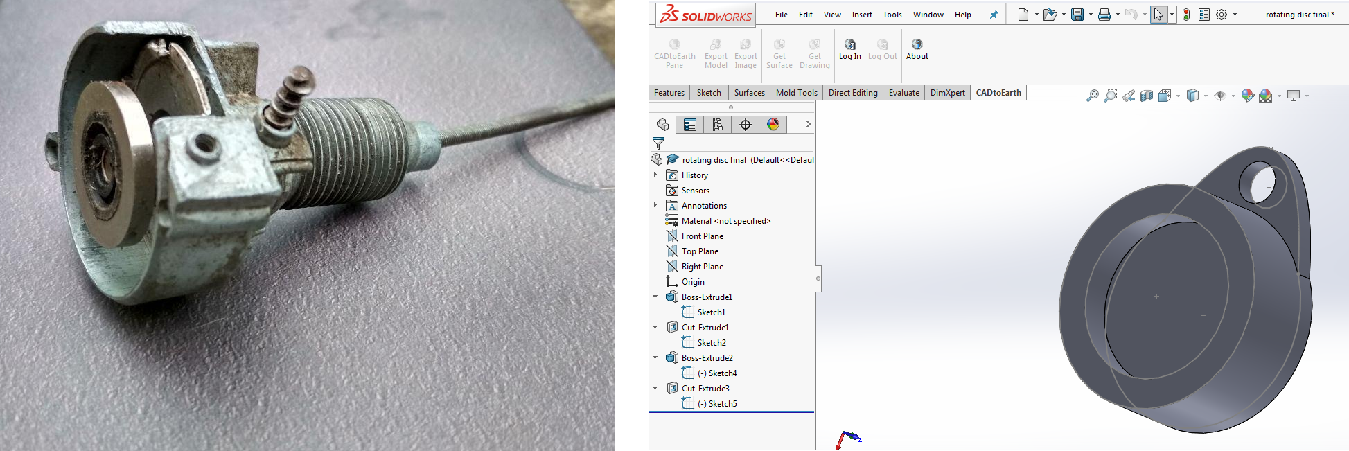
The magnet has to be rotated along with the spinning disc and a suitable "rotating disc" had to be designed. The above image on the right shows the part designed which will press fit onto the shiny disc of the reused part. The designed part had a hole for placing the magnet from the top. The magnet is mounted at the outer periphery of the designed part for getting a distinct pulse at the sensor. The size of the part was fixed taking account of this and the dimensions of the housing which was in turn depended on the physical dimensions on the motorcycle.
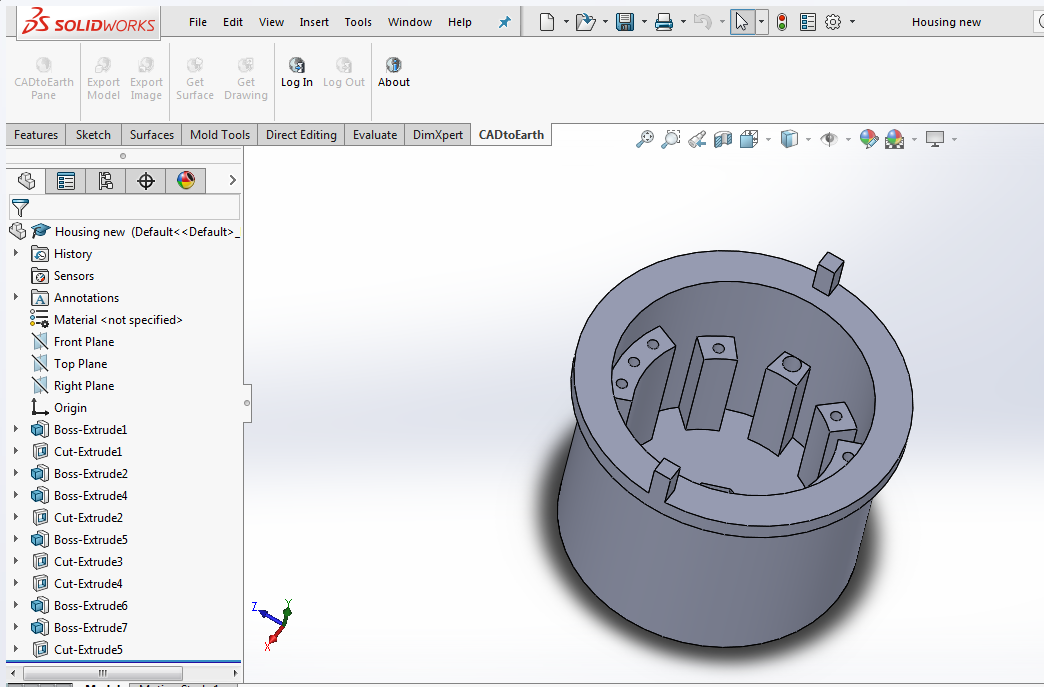
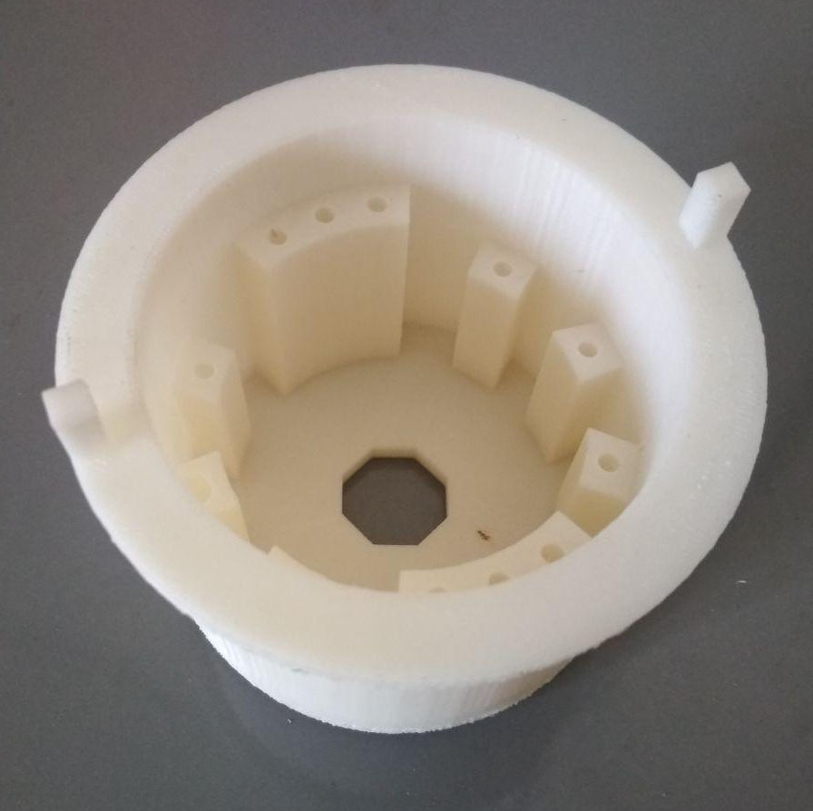
The main "housing" was next designed by taking care of the actual measurments on the motorcyle and the reused part. A hexagonal shaped hole was provided at the bottom to hold the reused part firmly. Several supports were provided at different heights to enable fastening of PCB's using screws. Two rectangular extrusions were given on the top to make it possible for press fitting the top acrylic covers.
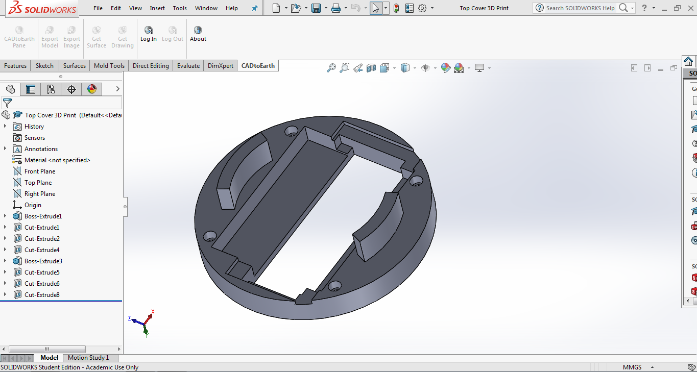
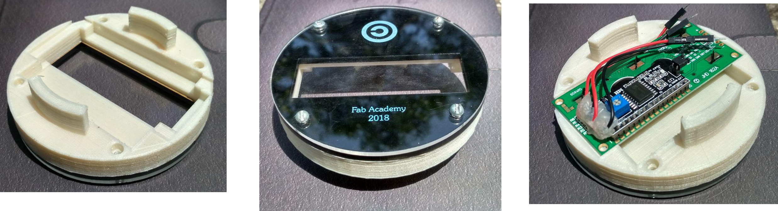
After 3D priting the housing, the extrution atop was found with insufficient strength. Also, the initial plan of the OLED as the output device didnt work out and had to be changed to a 16x2 LCD. To accomodate this LCD, and to support the top acrylic covers, another part was designed in SOLIDWORKS. The "Top Cover" was designed to hold the LCD in place and also to press fit onto the main housing. A extruding arc shape was given to enable press fitting onto the main housing. The height of the extrusion was fixed such that the "Top Cover" will hold the main PCB against the two supports from below, thereby avoiding srews on the PCB and enabling its easy dismantling. Provisions were provided for fastening the acrylic top covers using screws. Unnecessary portions were cut out to reduce the consumption of material during 3D printing. Below image shows the designed part from below.
The drawing for the top acrylic cover's were designed to be laser cut and is available in the link below.
Download the Mechanical Design Files
More on Computer Aided Design during the CAD Week and Computer Controlled Cutting week
3D Printing & Laser Cutting
The rotating disc was 3D printed in PLA using a fill density of 40% and shell thickness of 0.8mm. The below image shows the rotating disc with the magnet mounted on the reused part.
The main housing was 3D printed in ABS with a fill density of 70% ands shell thickness of 1.2mm, for the improved strength to withstand the stresses developed during and when installed onto the motorcycle. Below image shows the 3D printed housing.
The "Top Cover was printed in PLA usinf a fill density of 70% and shell thickness of 0.8mm. The image below shows the 3D printed "TOP Cover", with the LCD and acrylic covers.
More on 3D Printing during the 3D Printing & Scanning Week
More on Laser Cutting during the Computer Controlled Cutting Week
Electronic Design & Production
Electronic Design & Production
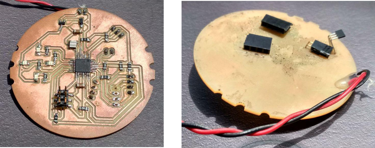
The electronic design and production was done during the Networking and Communication week when the board was designed along with the main housing for the speedometer. The diode, regulator and the connecting wires were soldered onto the board made during the week. The pin heads except the ISP were desoldered and soldered from below. The hall effect sensor was also soldered from below to detect the magnet mounted on the rotating disc. Below image shows the final board after stuffing and rearranging. The six partial holes made for screws can be seen, which was made manually by file'ing. These holes was later found to be of no use by designing the "Top Cover" which heold the PCB into place. Here is the Datasheet of AtMega 328P
The below image shows the final board ready to be assembled into the housing. The hall effect sensor and the pin head for connecting I2C LCD can also be seen.
Download the Electronics Design Files
More on Electronics Design during the Electronic Design Week
More on Electronics Production during the Electronics Production Week
Programming the MCU
Arduino code for a tachometer was obtained from this webpage which was modified to calculate the speed and distance and also to drive the LCD using an I2C module. Below is the final sketch which was uploaded to the MCU.
  // This programme is written for the working of a digital speedometer for a motorcycle.
  // The rotation of the wheel is transferred through a cable to a rotating disc that houses
  // a magnet. A full revolution of the wheel is equal to one full revolution of the disc.
  //
  // Akhil Hari 25-06-2018
  // Fab Academy 2018, Fab Lab Trivandrum, India
  // Final Project
  //
  // This programme is made by modifying the programme written and published by Richard Baker
  // on GitHub
  // https://github.com/rtbaker
  // https://github.com/rtbaker/ArduinoTachometer/blob/master/ArduinoTachometer.ino
  //
  // The original programme has been modified by communicating with the LCD over the I2C protocol
  // and also by displaying the distance travelled onto the LCD.
  //
  //
  // MCU - ATmega 328P (32-pin TQFP)
  // The MCU is connected to the I2C module which will drive the LCD.
  // The SDA & SCL Pins of the MCU and the I2C module are connected.
  // The SDA & SCL Pins of the MCU are pulled up externally for I2C communication.
  // The MCU and the I2C module have a common ground and supply voltage.
  // Output of the Digital Hall effect sensor is connected to pin PD3 of the MCU (Arduino Pin No.3).
  // PD3 is the interrupt Pin 1 of the MCU. By default, the output of sensor is High.

  #include <Wire.h>               // Includes library for I2C communication
  #include <LiquidCrystal_I2C.h>  // Includes library for I2C communication with LCD
  //Set the pins on the I2C chip used for LCD connections:address, enable, R/W, RS, D4, D5, D6, D7, backlight, backlightpol
  LiquidCrystal_I2C lcd(0x3F, 2, 1, 0, 4, 5, 6, 7, 3, POSITIVE);

  // Stating the Variables
  volatile byte rpmcount; // volatile byte are variable stored in RAM and is more accurate for handling interrupts.
  unsigned long rpm;      // unsigned long are extended size variables used for number storage and stores 32 bits.
  unsigned long velocity;
  unsigned long distance;
  unsigned long distancenow;
  float totaldistance;    // float is used for numbers with decimal points and stores 32 bits.
  unsigned long timeold;

  // Setting up the pins
  int sensorPin = 3;

  //Interrupt handler called once per revolution as the magent passes the sensor
  void rpm_tick() {
    rpmcount++;       //increment the value of the variable rpmcount
  }

  void setup() {
    // Hall effect sensor triggers on FALLING (change from HIGH to LOW)
    attachInterrupt(1, rpm_tick, FALLING); // a trigger on Interupt Pin 1 will execute the function rpm_tick
    // set up the LCD's number of columns and rows:
    lcd.begin(16, 2);
    // Print a message to the LCD.
    lcd.setCursor(0, 0);
    lcd.print("Fab Academy 2018");
    delay(1000);
    lcd.clear();
    // Declaring the initial variable values
    rpmcount = 0;
    rpm = 0;
    timeold = 0;
    velocity = 0;
    distance = 0;
  }

  void loop() {
    delay(1000);     // Dealy given to update the display after every second and also to process interrupts during the time.
                     // By observing serial data, it was understood that the display actually refreshes in 1062ms,
                     // 62 ms being the time taken by the MCU for execution.

    //Don't process interrupts during calculations
    detachInterrupt(1);

    // Time between now and previous display update
    unsigned long now = millis();            // Stores the number of milliseconds since the program started into a new variable called "now"
    unsigned long diff = now - timeold;      // Calculating the time elapsed after the last calculation.

    rpm = (60.0 * 1000.0 / diff) * rpmcount; // Calculating the RPM of the disc mounted with the magnet.
    velocity = (rpm * 0.11304);              // Converting the RPM into speed. Diameter of wheel = 60cm.
    distancenow = (velocity * 5 / 18);       // Distance travelled in between the iterations.
    totaldistance = distance + distancenow;  // Total distance travelled.
    distance = totaldistance;                // Storing the total distance travelled into a new variable.
    // Display the result
    lcd.setCursor(0, 0);
    lcd.print("Speed = ");
    lcd.print(velocity);
    lcd.print(" Km/hr ");
    lcd.setCursor(0, 1);
    lcd.print("Distance = ");
    lcd.print(totaldistance / 1000);
    //lcd.print(" Km");

    // Reset
    rpmcount = 0;
    timeold = millis();                     // Storing the total time elapsed into the variable "timeold"

    //Restart the interrupt processing
    attachInterrupt(1, rpm_tick, FALLING);  // restart counting the interupt's.
    digitalWrite(sensorPin, HIGH);          // making the interrupt pin high for avoiding tristate.
  }
More on Arduino IDE during the Embedded Programming Week
More on hall effect sensor during the Input Devices week and Interface & Application Programming week.
More on LCD during the Output Week
Integration & Testing
The below image shows the old analog speedometer atop the motorcycle which is fastened using a U-shaped clamp and a nut. The image on the right shows the speedometer removed.
The image shows the newly made housing and the rotating disc installed on the motorcycle. The magnet was glued and taped to avoid the possibility of dislodging during testing.
The below video shows the rotating disc successfully working during a test ride. A small jerk was observed during the operation which happened due to a protruding screw thread which was forced against the housing. After fixing the issue, there was no jerk and the rotating disc with the magnet was revolving smoothly and ready to "interrupt" the MCU!.
After the successful test ride of the rotating disc, the device was assembled and tested at lab after powering on with a 9V battery. The rotating disc was rotated by manually rotating a speedometer cable and the device was found to be working perfectly.
On the day before the final presentation, the LCD module started to show signs of abuse and was replaced. The video recording happened side by side and the only thing left was to record a working footage during a ride and to prepare the presentation slide and video. The speedometer was installed atop the motorcycle and powered up by connecting to the 12V battery of the motorcycle. It worked smoothly (except for few instances during when it showed speed as 0 while it was not) and attempt was made to record the on board footage. The footage of the actual working was so jerky and the LCD display was not rendered properly to read the text displayed. During the process, the monsoon clouds started making love with earth rinsing the speedometer with water. Few drops of water were observed underneath the clear acrylic which got in through the holes of the screws. After a sleepless night the day before, presentation.png was prepared using Google Slides and presentation.mp4 was made with Openshot and was presented to neil on time. Below video is the final presentation video which shows the assembling and working followed by the presentation slide.
Issues to be addressed
Making it weather proof is the major issue to be addressed which can be done by making use of gaskets. The total distance travelled have to be stored to the EEPROM of the MCU so that it works as a proper odometer. The frequency of accessing the EEPROM is to be kept minimum to avoid damaging the EEPROM.
What has worked and what hasn't
The procured OLED didnt work and had to be switched over to LCD. The housing was designed to be adaptable and it worked to accomodate the LCD instead of the initially planned OLED. I accidentally damaged the magnetometer sensor by reversing the supply and ground pin and the plan for the compass had to be dropped for the replacement was not to arrive before 18th. The digital hall effect sensor made things easier than the analog one used during the weekly assignments. The housing was designed to hold the top acrylic covers by press fit onto the protruding parts. However, the extrusions broke for the low fill density and an additional cover to hold the acrylic had to be designed and 3D printed.The documentation didnt happen properly and a proper working video of the speedometer installed on the motorcycle couldnt be shot. On the day of my final presentation, during the attempt to record on board footage, my laptop got soaked in rain and stopped working. I was left to push the slide and video which made me nervous and slightly unsettled. However, everything was completed on time by configuring git and pushing the slide and video from another computer at our lab.
What have i learned
Fab lab is a place where education and experience go in tandem making the learning complete. I learned to make almost anything by using the principles and applications of digital fabrication and also, developed the skills needed for the same over the weekly assignments. On january 17th, i had a minimal knowledge on CAD and digital fabrication, and almost nothing on electronics and programming. By the time this is written, i have developed my skill in computer aided design to a profound level, and have gained the knowledge and confidence to design and produce electronic circuit that are not too complex. In terms of programming, i can now understand Arduino sketches (and a little C) and modify it to my needs. Over all the above, i have this belief that i could learn anything by investing time and by proper documentation.
Apart from the learning and acquiring of skills, I'm left with a feeling of joy in being a part of a greater community, that is set to make this world a better place by bestowing people with the ultimate justice of freedom. More than what i learned through the weeks, i cherish the learning to respect and properly attribute the "collective intellect" in our work's. Fab lab community has enabaled me to stand on the shoulders of the giants (and not on their toe's) to see far more further, making myself indebted for the advancement of the community. "Fab Academy" is something to be experienced in life that will impart confidence and make us more gentle and humble.