Week 3
Computer Aided Design
Computer Aided Design is the craft of using CAD sotware in designing and protoyping of things. We were introduced into types and practices, and also the various softwares available for 2D Design, 2.5 Design and 3D Design. In addition to this, we were also introduced with creating and editing auido and video, simulations and game engines. This weeks assignment was to model a possible final project in a raster, vector, 2D and 3D softwares. and also to render, animate and simulate it.
2D - Raster vs Vector
There are two main type of image files: Raster and Vector. Raster images are created with pixel-based programs or captured with a camera or scanner. Vector graphics are created with vector software and are used primarily in manufacturing. The main differences are summarised below.
| Raster (Painting with Pixels) | Vector(Drawing with Vectors) |
|---|---|
| Image is made up of several pixels. | Images are made up of shapes defined using mathematical formula. |
| When scaled to a bigger size, loss of quality | Can be scaled infinitely |
| Each pixel is a colour | The colour of the outline, and the inside fill of a shape can be defined. |
| File Types: .jpg, .gif, .png, .tif, .bmp, etc. | File Types: .svg, .ai, .cdr, .eps etc. |
| Larger file size | Smaller file size |
| Smooth colour grading. Used in photographs etc | Colour of the shapes can be easily changed. Used for machining with cnc machines. |
| Softwares:Photoshop, GIMP etc | Softwares:Illustrator, CorelDraw, InkScape etc |
GIMP
GNU Image Manipulation Program (GIMP) is free and open source raster image editing software. GIMP was used to create a thumbnail image for the week 2 webpage by combining the logo of Ubuntu, Git & Atom and so as to integrate it into the webpage. The three logos were downloaded from the internet and opened it in GIMP by cliclking File > Open, and after selecting the images, click open.
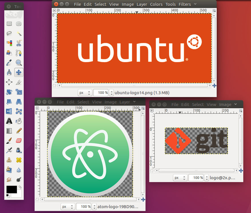
By cliclking Tools > Selection Tools we can select a particular region of the image. It is possible to select a rectangular region, elliptical region, region by colour etc. After selecting the rectangular portion in the ubuntu and git logo, click Image > Crop to Selection to crop the image as displayed below.
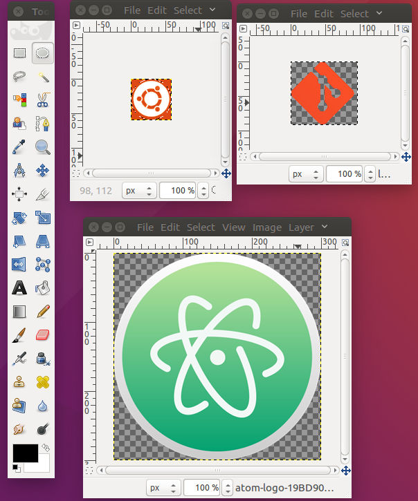
Save the individual images and then open a new Gimp window. Click File > Open as Layers and select the three images. The images will be imported in three layers one stacked over the another. With Gimp, we can work on the three laeyrs individually and simultaneously. The image can be worked in each layers with the help of the Layer menu in GIMP.
1. Layer > New Layer Creates a new layer placed on top of the existing layers. We can create a white or transparent layer, layer for the foreground and background colour with its width specified.
2. Layer > Stack To stack the layers on top of each other and to switch between layers.
3. Layer > Transform To rotate the layer.
4. Layer > Scale Layer To resize a layer by specifying height and width.
5. If we want to crop a particular layer, select that layer by using Layer > Stack and then click Tools > Selection tools and select the required area. Then clcik Layer > Crop to Selection to crop the individual layer.
The Atom logo layer was scaled down and placed in the required manner. After arranging the layers, Image > Fit Canvas to Layers was clicked to fit the canvas to layers. A new white layer was added and was stacked to bottom by clicking Layer > Stack > Layer to bottom to get the follwing image.
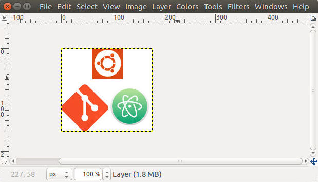
The image was exported as a jpg image by clicking File > Export As and the file was saved with a .jpg extension after selecting the quality. We can reduce the size of image files by making use of this option. The red area around the ubuntu logo was painted white using the paint brush tool available in the toolbox. To open the tool box, press Ctrl + b. The colour of the paint brush can be selected by clicking the rectangular area at the bottom of the toolbox. The final image is shown below.

Download Design Files
Inkscape
Inkscape is free and open source vector graphics editor. In my final project, the top covering piece for the speeedometer was to be made in Plywood. The plywood had to be cut to precise dimensions for press fit and also, engraving of the north direction was planned. I modelled the part in Inkscape so that the kerf of the laser cutter can be taken into account while designing.
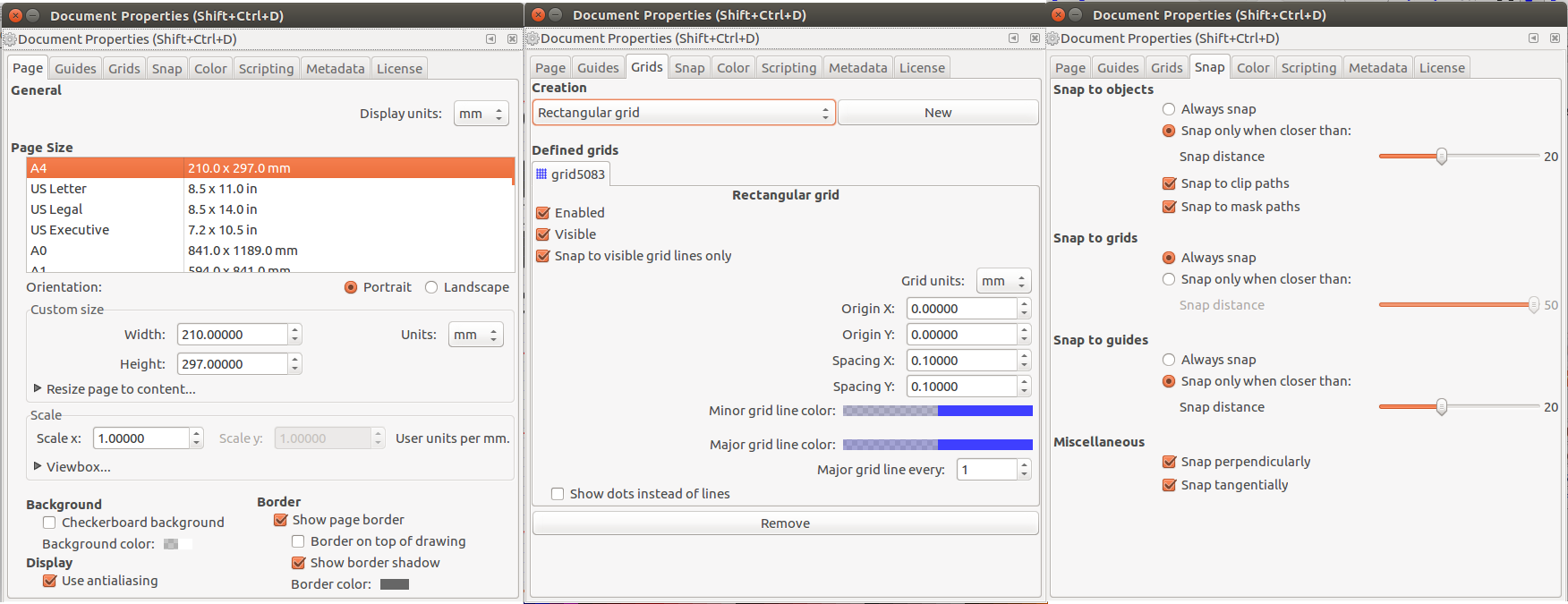
To set the document properties, click File > Document Properties. The document size, units, grid spacing, snap etc can be configured from the window which opens up.
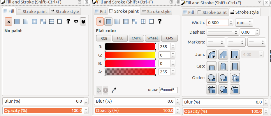
In Inkscape, different mathematical curves define the shape. The properties of the curves can be changed according to the need. The width of the curve is known as Stroke. The area enclosed by any curve can be filled with any colour using the Fill option. Click Object > Fill & Stroke to edit the properties of any curve. In addition to the colour, the width of stroke is of great use during laser cutting, for the kerf can be accounted here. The colour and intensity of the fill inside any curve is also of great use during laser cutting for it defines the depth of engraving.
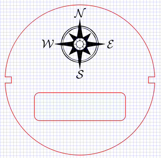
By selecting the Circle in the left pane, a circle was created. The properties of the circle can be changed by entering the value at the top of the window. The colour of the stroke was set to red and the width was changed to 0.3mm.
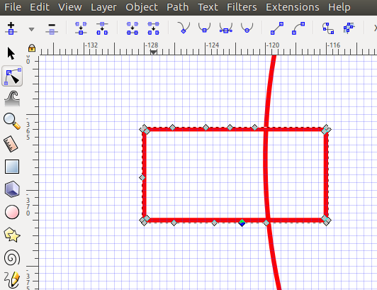
Similarly, two rectangles for the slots for press fit was drawn and the stoke width and colour was set. By clicking Object > Transform the objects can be moved, scaled and rotated. By selecting the rectangles, the rectangles were moved to keep it symmetrical with the circle.
Next step was to trim the unwanted portions of the rectangle. There is no direct way to trim objects in Inkscape. However, it can be done by editing the path of the curves.The strokes have to be first converted to path by selecting the stroke and by cliclking Path > Stroke to Path. By clicking, Edit path by nodes additional nodes can be added, and the path can be changed to the need.
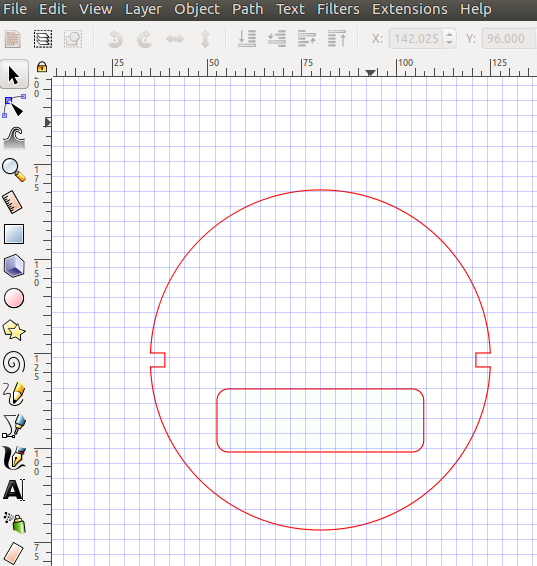
The unwanted portions of the rectangle and the circle was removed by deleting the nodes and by editing the paths. Another rectangle with rounded corners were added to house the LCD display. Below image shows the rectangles and circle after the unwanted paths were deleted.
Another useful feature in Inkscape is to convert Raster Images into Vector. To import an image into Inkscape, click File > Import. After importing and selecting an image, click Path > Trace Bitmap to open a new window in which we can set the number of brightness steps to import. Increasing the number of scans will give a high quality with a compromise on the performance of the PC. This image was imported to trace the bitmap.
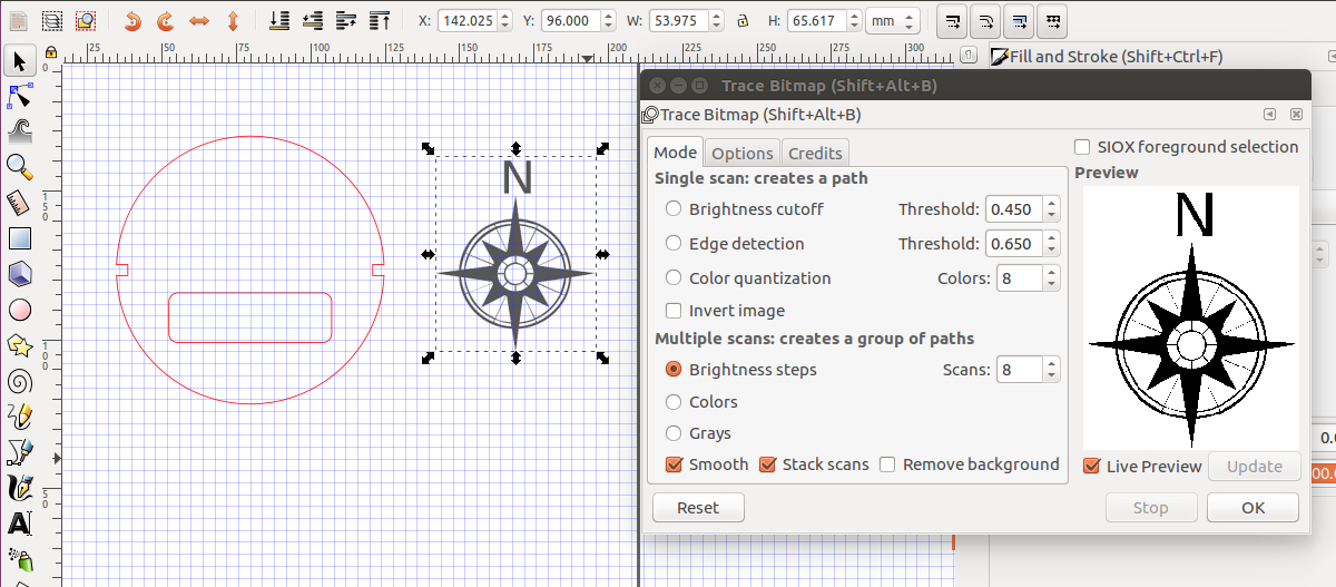
The converted bitmap image can be moved to the required place, and can be edited by editing the nodes. I set the number of scans to 2, and the resulting bitmap had some minor imperfections which was corrected by editing the nodes. Below is the final image after scaling down the traced bitmap and including the texts for the four directions. As the traced bitmap was for engraving, the fill was set to black.
Download Design File
3D Design - Parts, Types & Softwares
The different parts and types of 3D design softwares are as listed below.
1. Constructive Solid Geometry : Constructive solid geometry is logic on shapes. It allows to create a complex surface or object by using Boolean operators to combine/subtract/intersect simpler objects
2. Constrained : The objects are constained with each other like tangential constrain, parallel constrain etc. The purpose of constraints in a design is to control and limit the behavior of the entities and bodies in relation to another entity, plane or body.
3. Hierarchical : A shape is defined and used multiple times in the model. The entire instance of the shape can be edited by editing a single entity.
4. Parametric : The enitre design is defined with respect to parameter's and the entire design can be changed by changing the parameter's.
5. Procedural & Algorithmic :3D models are defined using a set of rules or algorithms.
6. Boundary (b-rep) : The boundary or the surface of the model is defined.
7. Function (f-rep) representations : The volume of the model is defined.
Dating with 3D Softwares
To familarise and to select the 3D softwares, attempt was made in FreeCAD, SolidWorks & Onshape
FreeCAD is a parametric 3D modeler made primarily to design real-life objects of any size. Parametric modeling allows you to easily modify your design by going back into your model history and changing its parameters. FreeCAD is open-source and highly customizable, scriptable and extensible. FreeCAD is multiplatfom (Windows, Mac and Linux), and reads and writes many open file formats such as STEP, IGES, STL, SVG, DXF, OBJ, IFC, DAE and many others.
SOLIDWORKS is a solid modeling computer-aided design and computer-aided engineering computer program that runs on Microsoft Windows. SolidWorks is published by Dassault Systemes. We were given with free license for educational use and i used the same.
Onshape Onshape is a computer-aided design (CAD) software system, delivered over the Internet via a Software as a Service (SAAS) model. It makes extensive use of cloud computing, with compute-intensive processing and rendering performed on Internet-based servers, and users are able to interact with the system via a web browser or the iOS and Android apps.It has a free version with some limitations.
The softwares have identical user interface with several workbenches like sketch, part, assembly etc. We can begin by drawing a sketch in 2D, and convert it into 3D by extruding/revolving around an axis etc. We can also directly begin to model 3d objects and do boolean operations upon them. In the assmebly workbench, we can assemble the individual parts and carry out simulations.
I began with FreeCAD for the capabilities shown by Neil during the lecture. It is a very powerful parametric design software but the user interface is a bit hard to figure out at the begining. We can add scripts for more advance design. I later switched over to SOLIDWORKS for the numerous tutorials available online. It was an easy switch from FreeCAD to SOLIDWORKS for both have almost similar interface. Onshape is exactly like SOLIDWORKS, but requires a fast internet connection. I modeled a potential final project in FreeCAD for this week's assignment. However, i switched over to SOLIDWORKS later during the course for some bug's associated with FreeCAD. In fact, fell in love with FreeCAD but was forced to date SOLIDWORKS for the time being!
FreeCAD
FreeCAD offers several workbench which we can switch at ease. One can draw 2D in "sketch workbech" and take it to "part workbench" to make it 3D. I tried to make a 3D model of a 3 axis gyro stabilised mount for smartphone's using FreeCAD.
1. Base

A base of size 200mm x200mm x100mm was created in the "part workbench". A cube was inserted and a hole was made on the top surface by drawing a sketch of a circle at the centre and then extruding it and making a cut of the objects.
2. Vertical Arm
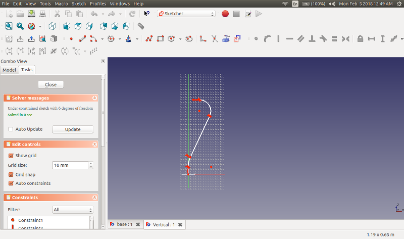
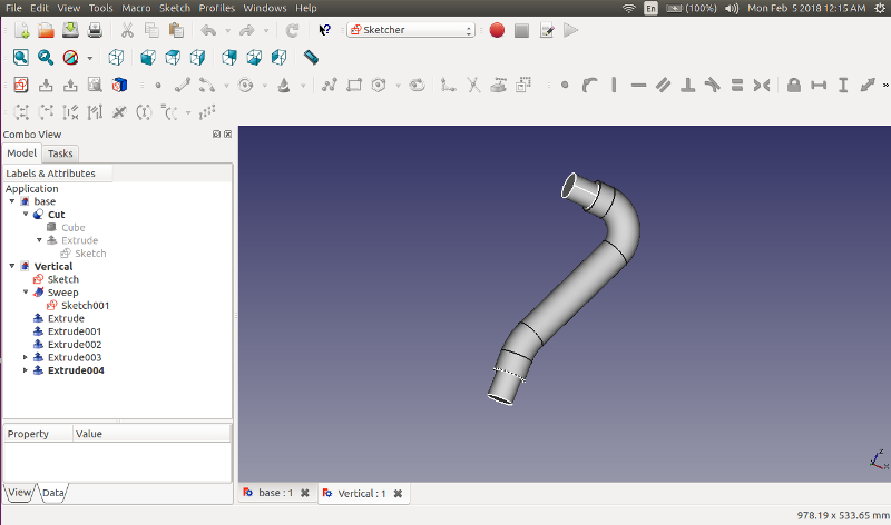
The vertical arm was made using the sweep function. A sketch of the profile was drawn and by sweeping a circle of 50mm dia around the profile path, the object was modelled. The round end blocks of 40mm dia are made by extruding circles from the face plane. The bottom end block will go inside the hole in "base" and can rotate around Z-Axis. The top end block will go inside the hole in "horizontal arm" and can rotate around the X-Axis.
3. Horizontal Arm.
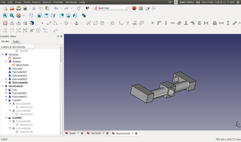
The horizontal arm can rotate around the X- Axis and also allows the "mount" to rotate around the Y- Axis.The horizontal arm was made in 3D by extruding different part over another. The holes were created by extruding a circle from the planes and making a cut of the objects.
4. Mount.
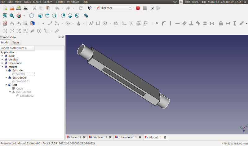
The mount is having an opening to hold the smartphone and can rotate around Y- Axis. Objects were extruded from the face to create the mount.
5. Assembled Model.
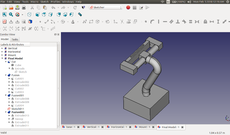
Each of the files were brought together and the pieces are kept in the assembled state by translating each part so as to fit together.
Download Design Files
SolidWorks
SOLIDWORKS was used for the rest of the weeks and below are the links to the assignments where SOLIDWORKS was used to design.
DNA structure for 3D printing - Week 6
Designing a Pulley Holder - Week 16
In addition to this, the speedometer housing, cover for the housing and the magnet mount for the Final Project was also designed in SOLIDWORKS.