Week 18
Wild Card Week - Composites
This weeks assignment was to Design and produce something with a digital fabrication process (incorporating computer-aided design and manufacturing) not covered in another assignment, documenting the requirements that the assignment meets, and to include everything necessary to reproduce it. Possibilities included (but are not limited to) composites, textiles, biotechnology, robotics, and cooking.
Composites
A composite material is a material made from two or more constituent materials with significantly different physical or chemical properties that, when combined, produce a material with superior characteristics than the individual components. The individual components remain seperate and distinct within the finished structure, differentiating composites from mixtures and solid solutions. One of the most common composite is reinforced concrete, in which steel and concrete are used, resulting in a material with high tensile and compressive strength. Another widely used composite is made from carbon fibre and epoxy which is having a high strength to weight ratio and finds its applications where weight has to be kept down without compromising the strength.
There are three types of composite manufacturing processes: open molding, closed molding and cast polymer molding.
1. Open Molding: Composite materials (resin and fibers) are placed in an open mold, and allowed to harden while exposed to air. Tooling cost for open molds is often inexpensive, making it possible to use this technique for prototype and short production runs. Open molding utilizes different processes, including hand lay-up, spray-up, casting, and filament winding.
2. Closed Molding: Composite materials are processed and cured inside a vacuum bag or a two-sided mold, closed to the atmosphere. Closed molding is used in cases where a two-sided finish is needed or if high production volumes are required.
3. Cast Polymer Molding: A mixture of resin and fillers are poured into a mold (typically without reinforcements) and left to cure or harden. This molding methods sometimes use open molding and sometimes use closed molding.
The Composite Labs website is a really informative website which gives insight into the process of composite manufacturing.
In case of composites, group assignment was to produce test coupons for the composite fabrication process done at our lab and the individual assignemnt was to read the safety data sheet (SDS) and technical data sheet (TDS) of the resins at our lab, and to design and fabricate a 3D mold and produce a fiber composite part in it, with resin infusion and compaction techniques.
Reading the SDS & TDS of the resin at our lab.
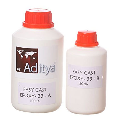
The resin we have at our lab is manufactured locally which was procured online. It is a two part compound with Part A & B which is mixed in proportion to harden. SDS & TDS for this particular resin was not avilable in the internet even after doing an extensive search. However, the details availble over the e-commerce website are the following.
1. This is a transparent epoxy resin with very less viscosity like water.
2. Can cure in 30 minutes if heated at 65 degree centigrade and poured.
3. Will cure at room temp in 24 hours
4. Non - Yellowing
5. Ratio of mixing: A:B = 2:1 by weight.
The general safety requirements and things to take care while using epoxy and fibre reinforcements are the following.
1.Always use protective gloves and googles.
2.The mix proportion should be strictly adhered to. Improper mix proportion may result in a soft material even after curing.
Producing test coupons
To get familiar with the composite making process and to analyse the effect of orientation of fibers in the composite, test coupons were produced using linen and jute fibers. The fibers were cut into rectangular shape in two different ways. The fibers were cut along the transverse direction to get a 90 degree orientation. To get a 45 degree oriented fibers, the rectangle was cut out diagonally from the sheet. We made 5 layer fiber composite with linen forming the outer surfaces and three jute layers in between. The linen at the outer surfaces were oriented along the length in all the three coupons. The first coupon was having the three jute layers oriented at 45 degrees. The second one was having the middle jute layer at 45 degree and the other two oriented along the length. The third coupon was made with all the layers oriented along the length.
The resin and hardener mixed in the proportion 2:1 by weight was applied onto the reinforcements using a spatula. Each layer of fibre was coated with adequate resin to soak it completely and the next layer of fiber was placed over. The process was repeated after keeping the successive layers. The test coupons were kept under a weight and allowed to cure for 24 hours.
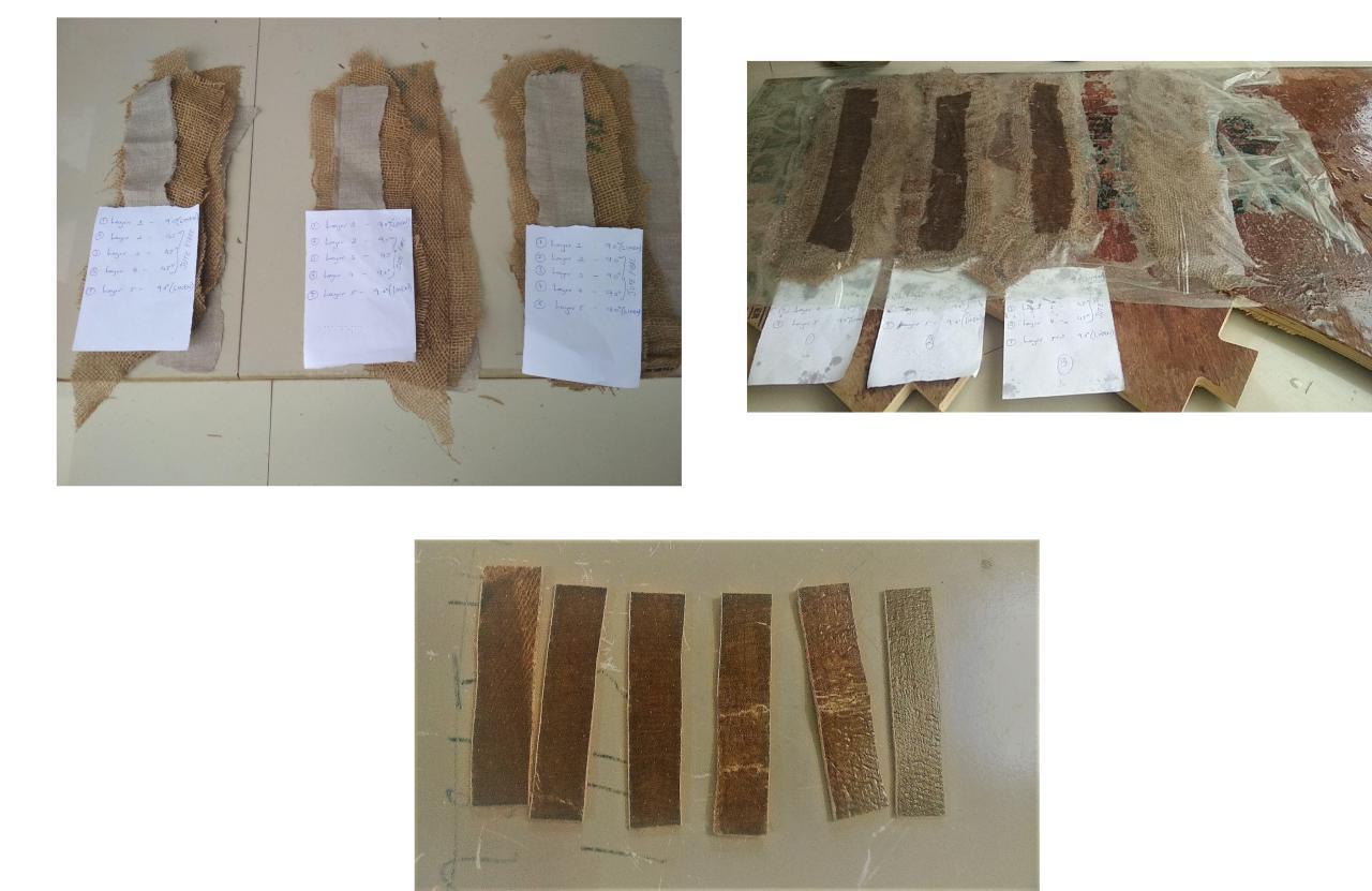
The coupons were cut out into regular shapes and was tested by bending along the longitudinal axis. The coupons where in all the three jute fibers were oriented at 45 degree exhibited superior properties than the other two.
Designing & Fabricating a 3D Mold
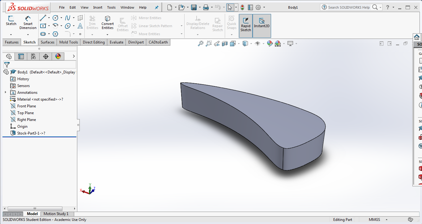
(Read more on Molding & Casting Week). A 3D mold is to be made from Plywood using ShopBot. A design cover for motorcycle fuel tank was designed in SolidWorks using the "Flex" feature. The cover had to be curved in both directions. The required shape was drawn using "spline" option in the skecth and was then extruded to a solid. Using the flex feature, the solid was then bend in two directions to obtain the profile of the fuel tank. Below is the image of the designed object.
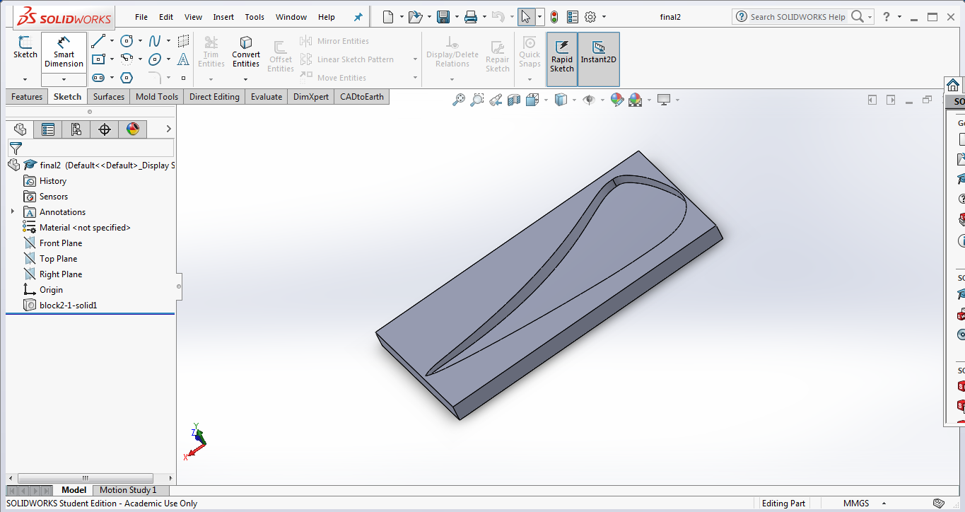
The designed part was subtracted from a solid rectangular part to make the mold. Below image shows the final design of the mold.
Download the Design Files
Using Shop Bot during Computer Controlled Machining week
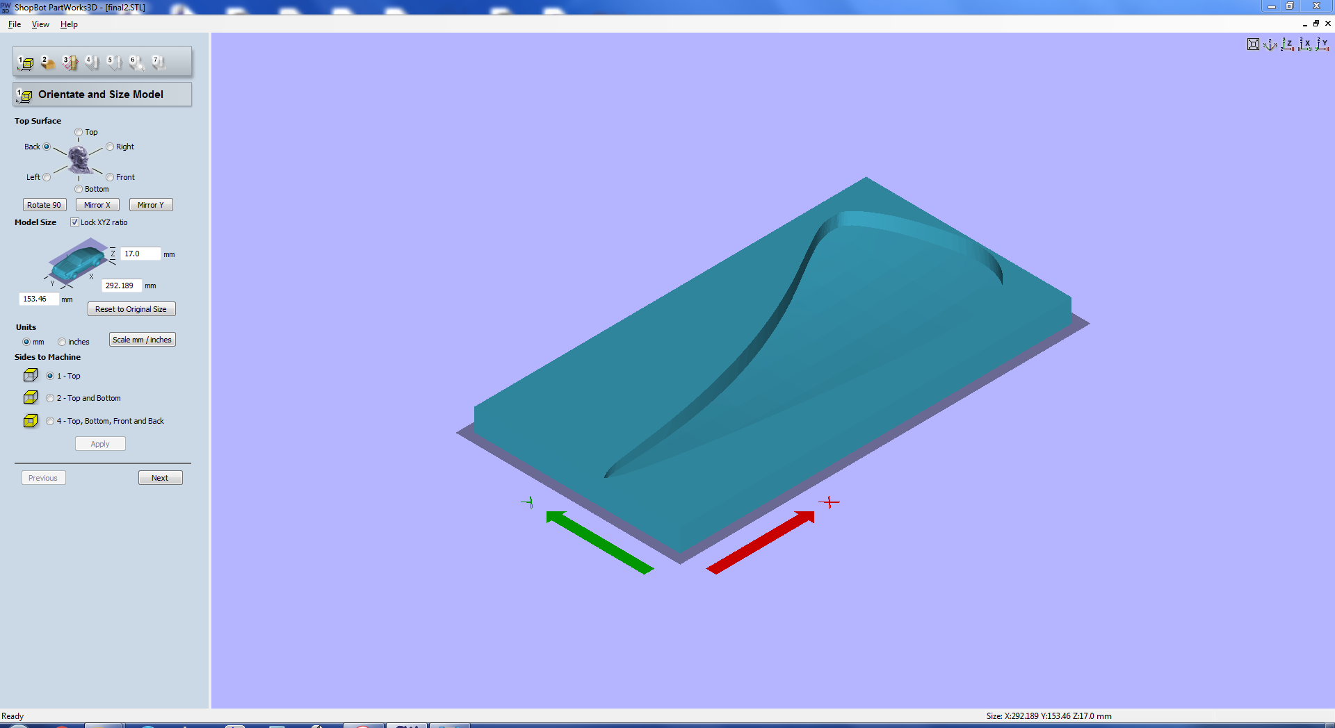
The design was exported as an STL file and opened in "ShopBot PartsWork 3D", the one for carrying out 3D milling in ShopBot. The below image shows the window of the software after opening the stl file.Here we can orient and size the stl model.
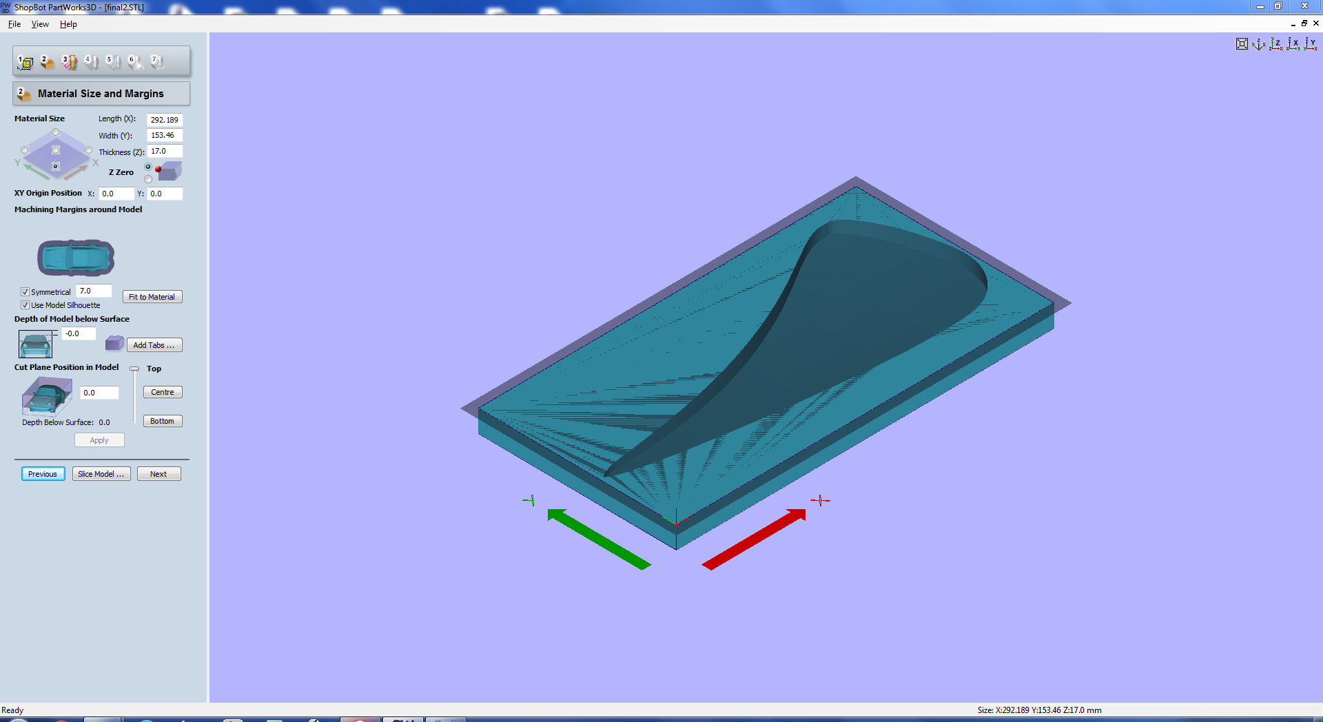
The below image shows the next window where we can set the origin and also add tabs if necessary.
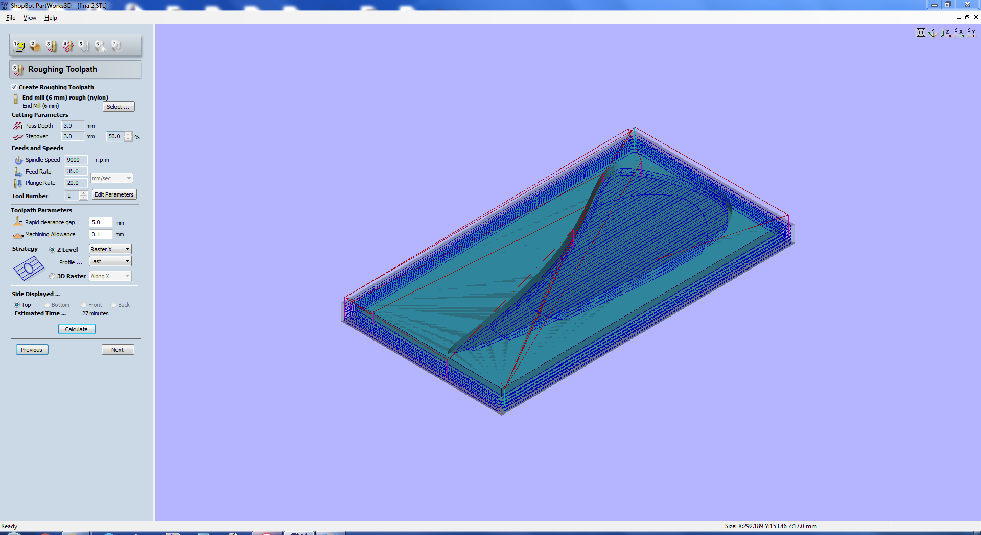
The milling operation will be carried out in two stages. The initial one is known as the "Rough Cut" which primarily removes the material to make the rough shape. The next stage is the "Finish Cut" in which the finishing operation will be done. The next window of the software is where we create the toolpath for the Rough Cut by specifying the drill bit and the cutting parameters. The below image shows the options for creating the toolpath for rough cut.
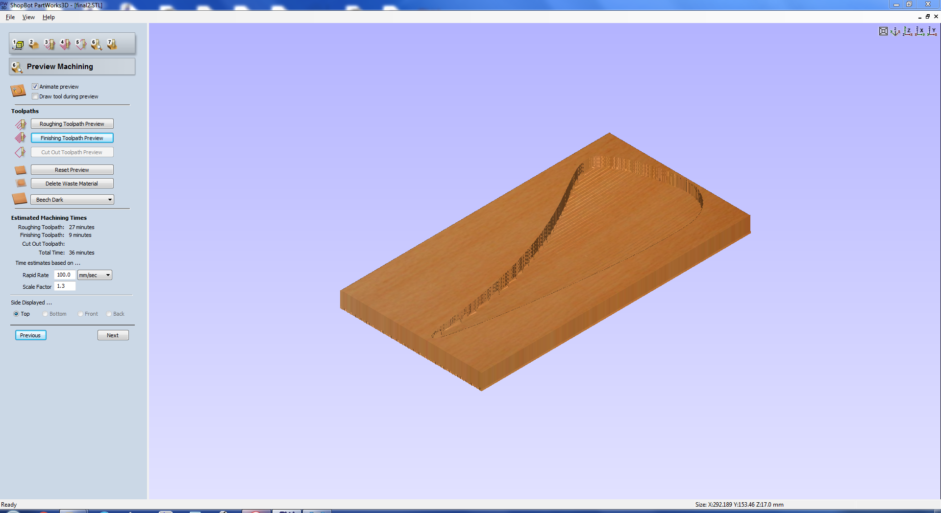
The next window is where we create the toolpath for finish cut. The appropriate bit has to be selected and the cutting parameters are to be configured here.
After creating and saving the toolpath's, the same will be send to ShopBot to create the mold.
After saving the toolpath for rough and finish cuts, the rough cut was first done with ShopBot. Below image shows the operation in progress.
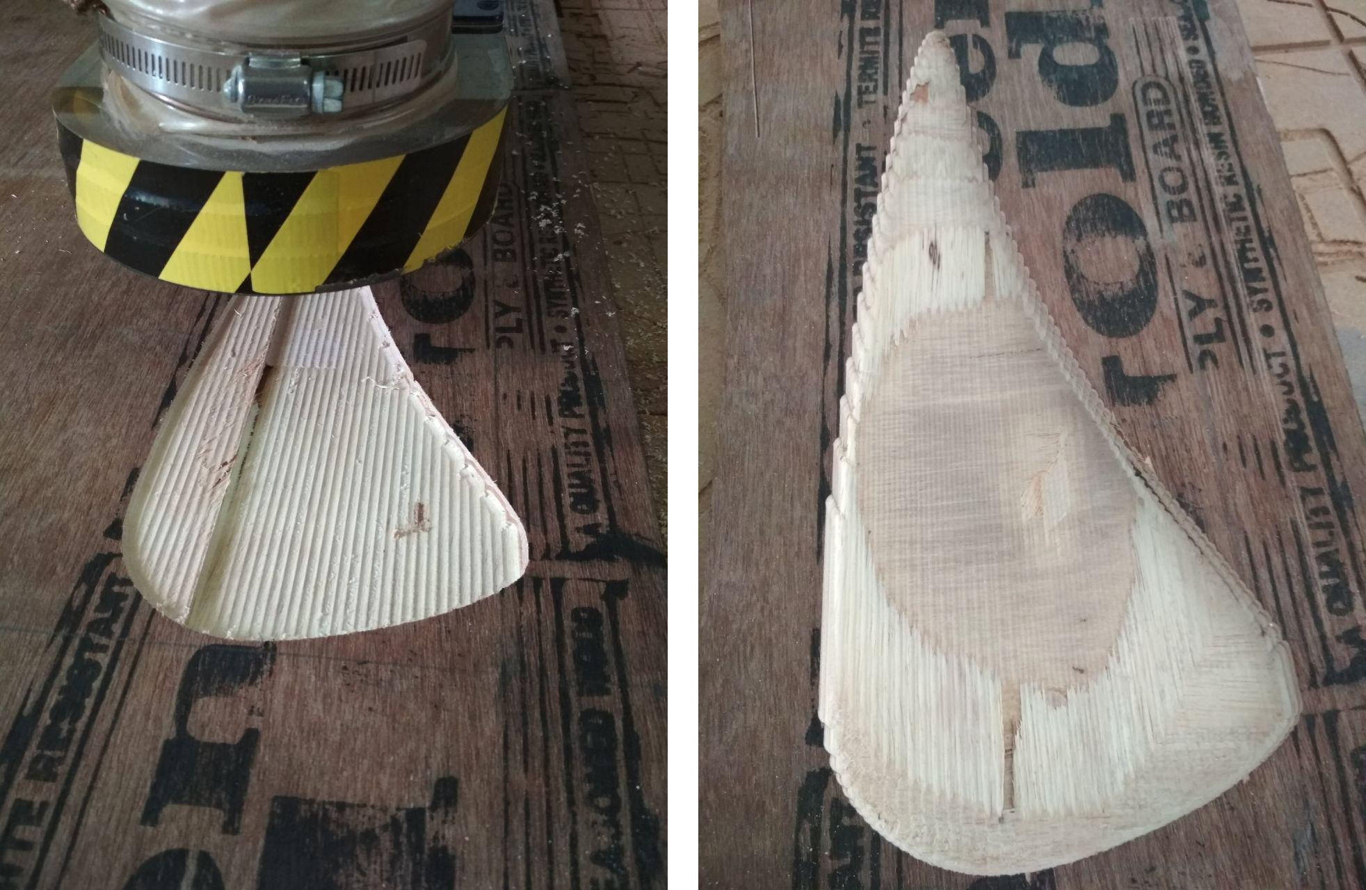
After completing the rough cut, the smooth cut was also done using the same bit. The image below shows the mould during and after the milling operation. For the bigger size of drill bit used for finishing, the sides of the mold was not having the exact curve as in the design. It was later manually, filed down to get a smooth curve.
Making a composite part
To ensure that the mold and part do not stick together, a "Release agent" is used which also reduces the amount of bubbles that occur between mould and part which ensures a proper composite. Several things like wax, silicone based solvents can be used as a thin layer to act as the release agent. Cello tapes were used as release agents in this case. Cello tapes were carefully stuck over the profile ensuring that no area is left out. In the process, cello tapes had to be overlapped which formed kinks and ripples which will affect the finished surface of the composite.
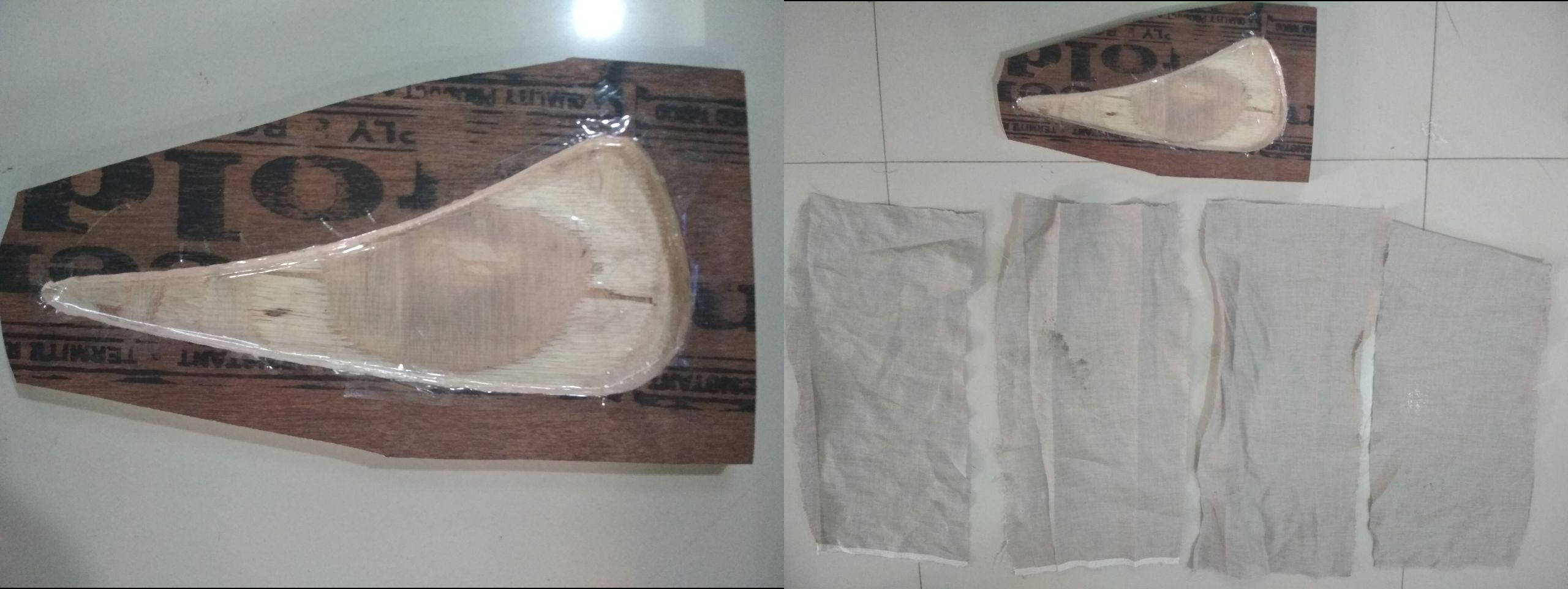
The next step was to cut the reinforcement fabric to the required shape and orientation. Linen cloth was available at our lab and it was used as the fibre reinforcement. The orientation of the fibers where set along the length so that the composite can bend more along the longitudinal axis. The above image shows the mold with the release agent and the pieces of the linen fabric cloth.
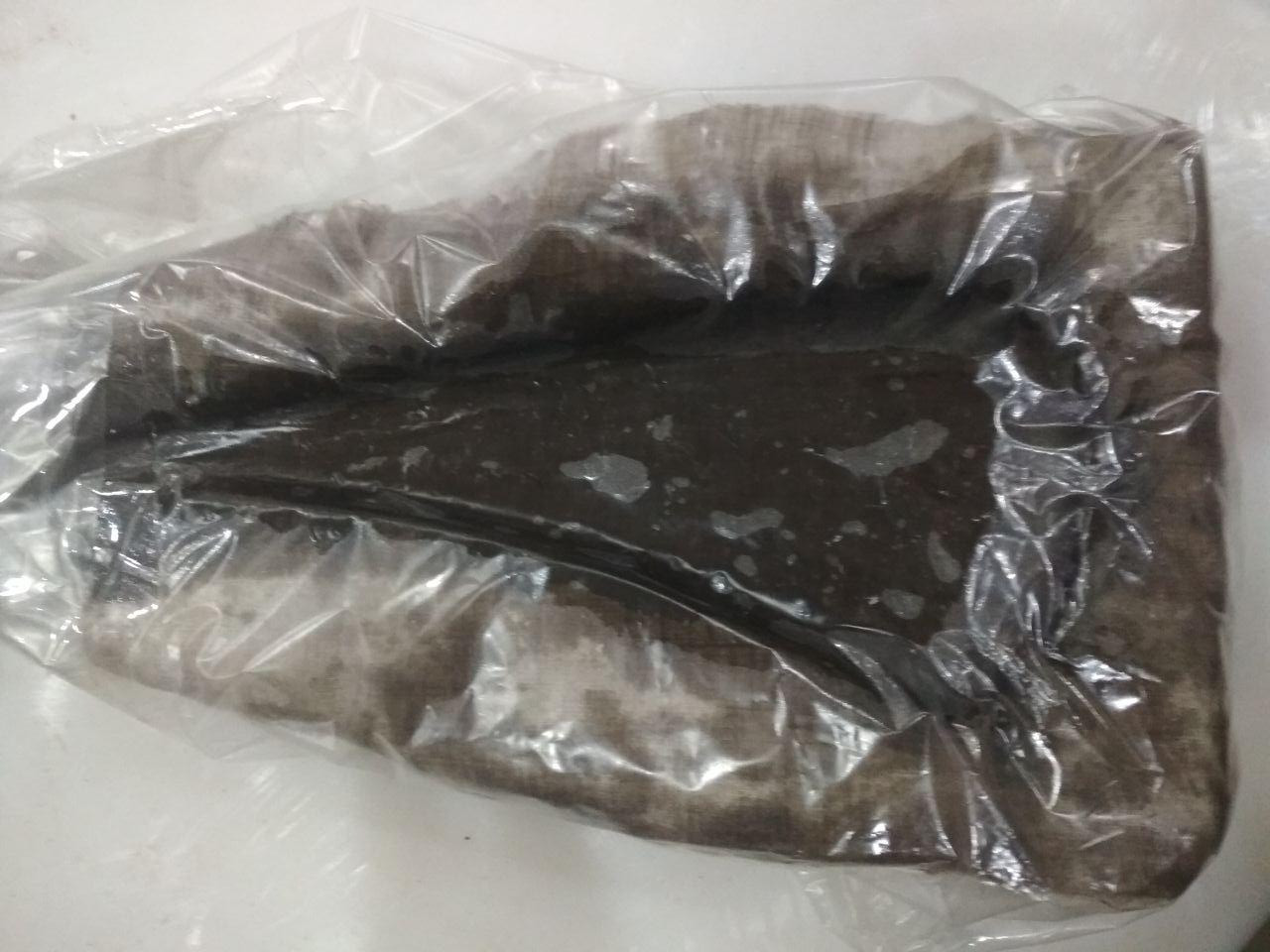
The epoxy and the hardener was mixed in the ratio 2:1 by weight and was thoroughly mixed using a wooden spatula. Care was taken to avoid the formation of air bubbles. A layer of the mixed epoxy was applied over the release agent using a sponge brush. The first layer of reinforcement was then kept over and the epoxy was applied over the fabric. The epoxy should be applied with a gentle pressure so as to ensure penetration well into the fabric. The reinforcement was pushed towards the mold at the corners so that it assumes the shape of the mold without any kinks and twists. The process was repeated after keeping the successive layers of fabric. Formation of air bubbles should be kept minimum at all stages of composite production. After placing the reinforcement and applying the epoxy, a perforated layer has to be kept over the epoxy layer so that, the excess epoxy can squeeze out when pressure is applied for curing. However, i forgot to place the perforated sheet.
After completing the process, the next stage is to place the mold inside the vaccum bag and to suck out the air using a vaccum pump. The vaccum process eliminates the air inside the bag with the atmosphere applying a pressure over the mold. The vaccum has to be maintained during the curing period. However, the vaccum process didnt work out well and i placed the mold under a sack filled with wooden dust for applying the pressure. Below image shows the composite just before the vaccum process.
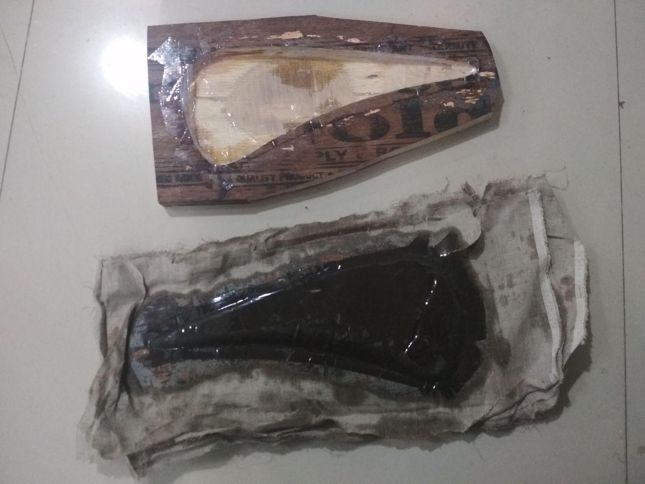
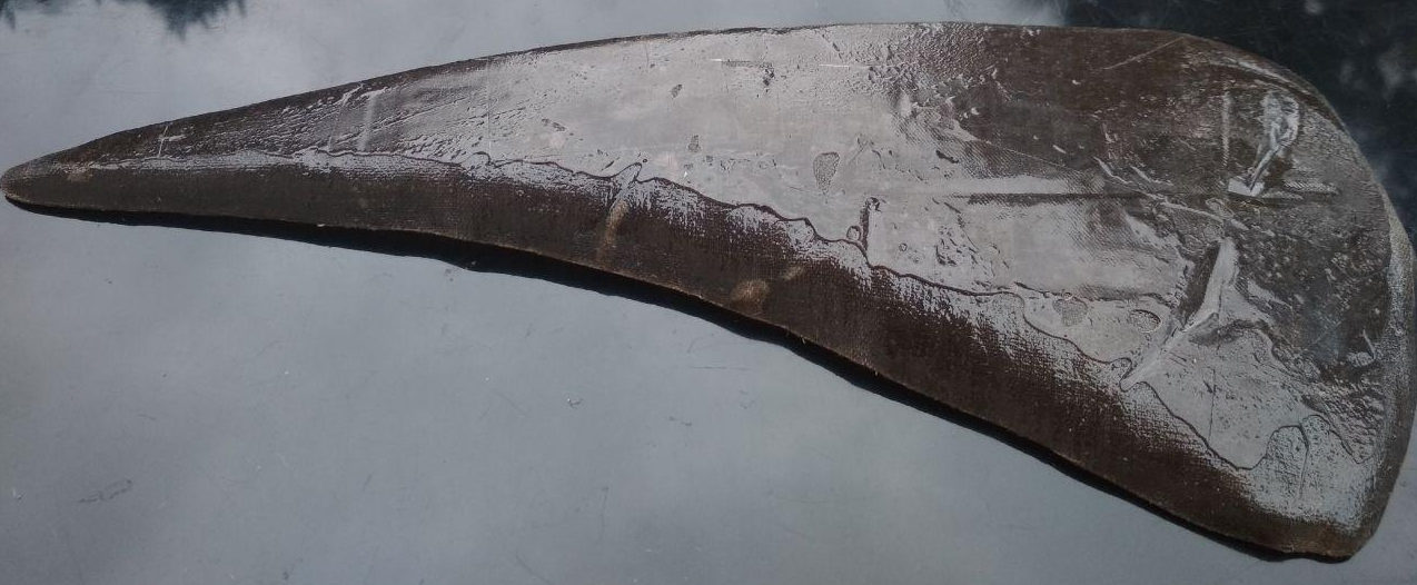
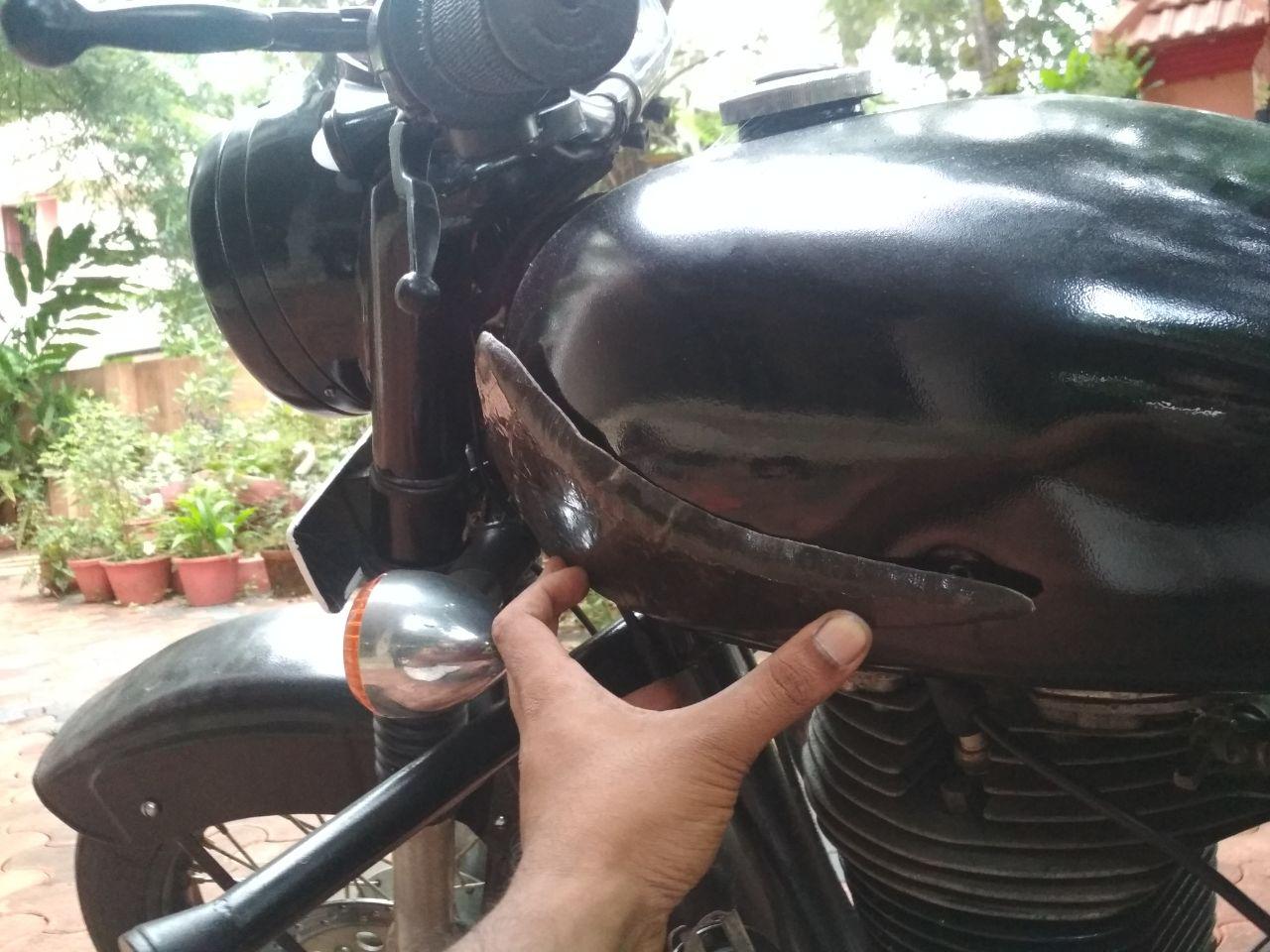
The composite was allowed to cure for 24 hours and was then removed from the mold. The removal was not a smooth process and the composite had to be pulled out from the mold by applying small pressure. Below image shows the composite after it was removed from the mold. The unwanted portions were cut using a knife and the final product can be seen over the fuel tank.
What I would do differently next time
1. Draft Angle to be incorporated into the design
It was difficult to release the part from the mold and also the part had a poor surface finish.
The reason for the same is to be attributed to the absence of draft angle in the mold.
Draft angle is the slope provided to the vertical face of a mold to facilitate the easy removal
of the casted part, thereby reducing the risk of damage during ejection. It takes account of the
shrinkage of the part during the curing time. Providing draft angles reduces the friction (due to the surface tension developed during curing)
between the mold wall and the part.
Providing draft angles in the mold will also
avoid surface scratches on the casted part during ejection and safeguard the mold against possible damages
during ejection of the part. The draft angle required for a mold depends upon the
depth of cavity, thickness of part, the geometry of the part, the surface texture of the part etc.
The draft angle also gives adequate space for the end mill to go and properly mill the bottom corners
in case of deep cavities.
For most materials and thickness, a draft angle of 1 to 2 degree is enough. It can be also as low as
0.5 degree. A general rule of thumb is 1 degree of draft for each inch of cavity depth. All material shrink towards the centre during
the curing/colling process and will exert pressure on the inner surfaces.
It is for this reason, the draft angles at the inner surfaces are kept more than that for the outer surfaces.
More detailed information on draft angles are available at the following websites.
Protolabs.com
revpart.com
2. Providing fillets
The shrinkage during the curing process will exert pressure on the inside surface and the corners.
To avoid developing stresses on the part, sharp corners and sudden change of cross section is to be avoided and
is the reason for providing fillets. Fillets avoids the concrentration of stress at corners and distributes it to a larger volume.
Fillets are also provided at the outer corners to reduce the surface tension at the corners for easy removal.
Below links are for more detailed reading.
OF ALL ON casting
Magic Precision
3. Proper Vaccum bag moulding or using a bag of sand instead of wood dust
The composite part made was having unevenness due to entrapped air and the lack of
proper compression. The less pressure applied by the wooden dust didnt squeeze out the excess resin and this
made the composite less compact, resulting in a low fibre density and decreased strength, which was evident from the
easeness with which the part bends.
The composite before and during curing, should be well compressed to force out the
trapped air and the excess resin. Vaccum bag process is a good way to achieve the same which
will make the composite stronger. In the absence of a vaccum bag, using a bag of sand will be
used to compress the composite for the increased unit weight of sand.
4. Increasing the step over
The milled mould was not having a smooth surface which could have been
avoided by using more step over. Step over is the overlapping area in
adjacent tool paths. However, increasing the step over will significantly increase the
time taken to finish the machining operation.
5. 3D scanning to get the surface profile
The curvature of the designed part was fixed arbitarily and was not
fitting to the fuel tank properly. It had to be bend to match the surface profile
of the fuel tank. A 3D scan of the fuel tank to obtain the correct pofile would have eliminted this error.
6. Taking care to put screw/nut inside the composite part to facilitate its fastening at the desired place.
A nut/screw if kept inside the resin and fibers before curing will integrate to the final part
and will enable the mounting of the part.