Week 8
Computer-Controlled Machining
This week's assignment was to test the runout, alignment, speeds, feeds, and toolpaths for the machine at our lab and to make something big.
Setting up the machine and design considerations
The machine we have at our lab is ShopBot with a bed size of 96x48 inch. The machine has a fixed base upon which we mount the material. The cutting edge of the machine is an end mill, of which the speed of rotation can be controlled. The end mill can move along the Z axis and the assembly which mounts the end mill can move along the X & Y axis making it possible for a 3D cutting. The end mill makes the cuts by removing the material along the predetermined path in successive layers. The speed of horizontal movement (on X-Y plane)of the end mill is known as "feed" and the speed along the Z axis is known as the "Plunge". Both the "feed" and "plunge" can be controlled using the bundled software (command console). The removal of debris is accomplished by the use of a vacuum cleaner which creates a vacuum around the bit and sucks the debris as and when it is formed. The bundled software of ShopBot is a command console which can only understand G-Code. The G-Code required for the operations are generated using another bundled software called "V-Carve".
The machine can do three types of operations, Drill, Profile (Cut) and Pocket.
1. Drill: In this operation, the machine makes a drill. By specifying the tool properties (diameter) and depth of drill, the operation can be carried out. The diametre of the drill is only dependent on (and equal to) the diameter of the tool. Even if a command to drill along a circular profile is given, it will only drill a hole at the centre of the circle.
2. Profile (Cut): In this operation, the machine cuts the material along a specified path. We have to specify the tool diameter, depth of cut and the side (relative to the path) on which the cut has to be made. The end mill can be configured to move along the path in three different ways. "In cut", "Out cut" and "On cut". If "Incut" is selected, the end mill will remove material along the inside of the path and the overall size of the material at every point inside the closed path will reduce by an amount equal to the diameter of the bit. If "On cut" is selected, the material will be removed equally from either side of the tool path. In case of "Outcut", the material will be removed from the outer side of the path.
3. Pocket: In this operation, the machine removes the entire material over an area formed by a closed path. The tool diameter and depth of pocket has to be specified. This operation is similar to engraving. The end mill can make the pocket in two different ways. In the first case, the end mill will remove material from the centre point towards the outer periphery of the closed path in successive passes. In the second case,the end mill will begin removing material from the outer periphery and move inwards.
Steps of operation & factors to be considered
1. Design
Like any other computer aided manufacturing process, the design is of paramount importance. For making a 2D cutting, the design file has to be in DXF format which is to be imported into "V-Carve". It will be ideal to design the model in 3D and to then export the 2D view needed for the cutting. A 3D model will enable us to assemble the different parts and to verify the assembly for any defects. The DXF file after importing into V-Carve has to be first examined thoroughly for any deviations from what is expected. The layout of the objects which are to be cut out has to be arranged in the software which will result in minimal wastage of material. Due to the type of tools used during the design and also due to file exporting properties of design softwares, V-Carve may not recognise closed paths to be closed. In such cases, the paths can be closed within the V-Carve software.
2. Material.
The material selected should be softer than the end mill available. To ascertain the hardness of the bit, the specification of the bit has to be checked. When compared to the hardness of the material, using a much harder bit will ensure less wear and tear for the machine and also the bit.
3. Mounting of the material atop the machine bed.
The material to be cut should be mounted atop a sacrificial layer which is to be mounted first atop the machine bed. The sacrificial layer should be firmly fixed on the machine bed with suitable type of fasteners and if screws are used, the screws should be kept sufficiently deep into the sacrificial layer so that it wont interfere with the movement of the end mill during operation.
Before mounting the material, the material should be checked for any defects and deformations. The thickness of the material has to be checked at various points so as to ascertain the depth of cut required for making a clean cut. The material is to be held firmly to the bed and should be held flat at every point before and while making the cut. Improper fastening of the material can induce vibration of material during the cutting activity and puts the end mill at the risk of breaking. The material can be fastened using various methods such as screws and clamps etc. Care has to be taken to keep the fastening object (screws and clamps etc) away from the tool path so as to avoid breaking of bit. If the sheet of material is having any bends, it will be ideal to place the sheet with its convex shape upwards so that the material can be held flat easily by fastening at the sides.
4. Setting up the machine.
Following factors are to be accounted during the setting up of machine.
A. Type of end mill.
1.Upcut end mill: While moving downwards and making the cut, this type of bit will eject the debris in the upward direction and gives a smooth finish at the bottom side of the cut. This is the most commonly used one for the ease of debris removal. This type of bit will have a tendency to pull up the material from the machine bed and can result in a rough finish at the top surface.
2. Down cut end mill: While moving downwards and making the cut, this type of bit will eject the debris in the downward direction and gives a smooth finish at the top side of the cut.
B. Origin.
The origin of the end mill (also of the mounted material) has to be set in all three directions. The origin on the three directions can be set using the buttons available in the command console. The coordinates of the bit will be displayed in the software. It is better to set the origin on the Z axis by using the plate provided with the machine. The plate is electrically connected to the machine and when the bit moves down and touch the plate, it creates a continuous circuit with which the machine will calibrate the origin on Z axis.
C. Horizontal Speed of movement (Feed) and rpm of the end mill.
These two factors are to be decided with respect to the hardness of the material to be cut and the hardness of the end mill used. In case of harder materials, the horizontal Speed of movement has to be reduced so as to give sufficient time for the end mill to entirely remove the material. The rpm of the bit has to be increased in the case of harder materials so that the bit can entirely remove the material before moving horizontally. An incorrect speed and rpm, can in fact make a faulty cut and could also wear out (or break) the bit.
If the feed is lesser than what is required, the bit will rotate at the same place even after removing the entire material. If the feed is more, the bit will move horizontally even before completely removing the material and this could end up in wearing out the bit at a faster rate and could even end up in the breaking the bit.
If the rpm is more than what is required, the bit will rotate at the same place even after removing the entire material. This could produce heat and the material could catch fire. If the rpm is less, bit will move horizontally even before completely removing the material and this could end up in wearing out the bit at a faster rate and could even end up in the breaking the bit.
The ideal speed and rpm for each material is to be found out by trail and error method. In the event of the right settings, the machine will make the sweetest of noise while making the cut.
5. Movement of the end mill along the paths
The type of cut i.e "Incut"/ "Outcut"/"Oncut" is to be selected for each closed paths. If the tool paths are very close to each other, the material in between the tool path could vibrate during the operation putting the bit at risk of breaking. In such cases, a pocket for entire depth is to be selected instead of cut.
6. Setting up of tab's and dog bones.
While the end mill almost completes the cutting along a closed path, a major portion of the material inside the closed path will have a tendency to get detached from the main piece and can start to vibrate during the last stages of the cutting operation along the closed path. This could result in an improper cut and also put the bit at the risk of breaking. In order to avoid this, a small portion of the material is to be left uncut so that the material inside the closed path won't vibrate during the closing stages of cutting. This uncut portion is called the tab's and can be configured in the software. Both the length and depth of the tabs can be configured in the software. The depth of tab will be measured by the machine from the bottom face of the material thickness specified. If the material thickness entered in the software is actually more than the actual thickness, the depth of tab created will be reduced and this has to be taken care while dealing with materials of varying thickness. After completing the cutting operation, the tabs are to be manually broken by using a sharp tool to remove the parts from the parent material.
At inside corners (during in cut), the bit cannot cut an exact 90 degrees. If the cut is a female slot for another male slot, the two pieces won't fit proper at the corners due to this shortcoming. To avoid this, dog bones are provided. By inserting a dog bone, at the 90 degree corner, the end mill will make an additional hole at the corner making it possible for the parts to fit together properly.
7. Creation of tool path and generation of G-Codes
The design file in DXF format has to be first imported into the V-Carve software. By clicking "Job Set Up" in V-Carve, the job size, material thickness and units can be specified. If the available material is away from the origin, the origin of the end mill can be offset using the appropriate option.
The next step is to check if the vectors are closed. It can be ascertained by clicking over the vectors. If the entire closed path is not getting selected, the vectors are not joined. The same can be joined by selecting the needed vectors and clicking "Join open vectors".
The next step is to create the dog bones. By clicking "Create Fillet" option, and by specifying the tool radius, the same can be accomplished. Click on the required junctions to create the dog bones.
The next step is to create the tool paths for the respective operation of drill, pockets and profile(cut). First, the drilling operation has to be carried out, followed by the pocket and profile. If the profile (cut) operation is first carried out, the material will become detached from the parent material except at the tabs portion. The lack of fastening will induce vibration and can result in improper pockets and cut and put the bit at risk of breaking.
The next step is to install additional fasteners to the mounted material so as to keep it firmly attached to the bed during the cutting operation. This is needed since the parent material will become discountinous once the cutting operation begins and chances are there to vibrate. To do the same, screws have to be installed at locations where in the tool will not pass. The selection of locations for the screws should be such that the entire portion of the parent material will be held down firmly during the operation. For doing the same, draw circles of radius equal to tool diameter at the desired locations. Select these circles and create a tool path for the drill operation at the circles. Generate the G-Code for the drill and run the G-Code in the command console. This will drill holes at the exact desired locations with which we can install screws.
The next step is to generate the tool path for the Pockets and Profile (Cut) and generate the G-Code and run the G-Code one after the other to complete the operation.
8. Running the G-Code & operating the machine
The generated G-Code is to be opened in the command console software of ShopBot. The machine has to be turned on and the spindle is to be engaged by turning the key. The spindle has to be then started by pushing the physical button for the same and the rpm of the spindle is to be confirmed from the monitor display before begining the operation. Once the spindle has attained the intended rpm as displayed, the cutting operation can be started by clicking the button in the command console. The person operating the machine should never leave the machine unattended and should be in a position to pause or cancel the operation in the event of such a need. The cutting operation can be paused by pressing the space key (or any other key). If the operation is paused, it can be resumed from where it was left, after starting the spindle again. In the case of any emergency, the operation can be aborted by pushing the physical button provided for the same. However, if the emergency button is pushed, the cutting operation cannot be resumed.
9. Safety Precautions.
The machine has to be operated with extreme care for the chance of
fire and getting injured. The bits spinning at high speed could initiate a fire
and adequate measures for fire extinguishing should be available. The debris of the material,
or in the worst case, a broken bit, could go in any direction and hence the operator
should wear safety glasses,gloves and shoes. Do not wear loose clothes and leave hair untied,
while operating the machine for these could even end up in fatal injuries. The person
operating the machine should never leave the machine unattended and should be
always close enough to the machine so as to pause or cancel the operation in
the event of such a need. In addition to the personal safety, certain measures
are to be taken for the safety of the machine also.
1. Before setting the origin on Z axis, first check if the continuity between the
plate and drill bit is detected by the software.
2. Ensure proper removal of debris during the machining operation.
3. Maintaining close attention to the sound of the machine.
If the machine makes any abnormal sound during the operation,
the pause button should be immediately pressed and the reason should be investigated and
rectified before resuming.
4. Ensure that the bit is spinning before the command for making the cut is given.
In case, the bit is not spinning, the bit will crash into the material and break,
for the bit will start to move horizontally without spinning and will hit
against the material and break.
5. Keep a close watch on the mounted material for any vibrations happening due to
loss of adequate fastening during the operation.
Making Something "Big"
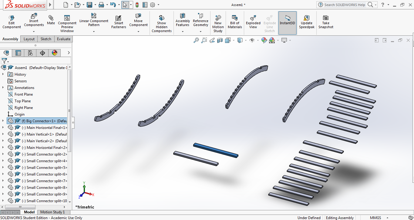
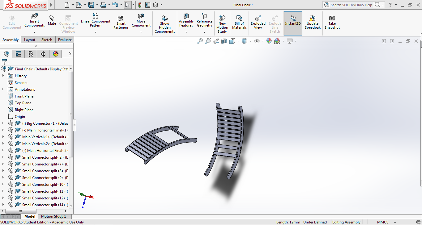
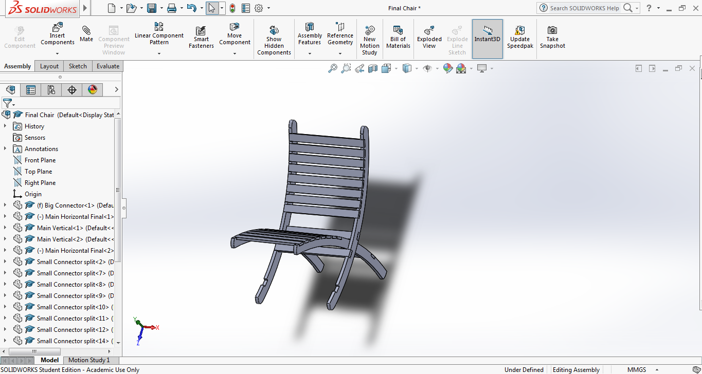
The computer aided design skills developed during the Computer Aided Design week and Computer Controlled Cuting week came handy during this week. To experience the process and to familarise the "ShopBot" available at our lab, I decided to design a detachable 2 piece chair which can be made by press and slide fit. The material available at our lab was plywood sheets of thickness 18mm and 12mm. The vertical and horizontal frame's of the chair was designed keeping in mind of the 18mm plywood and the connecting members with 12mm. The 4 individual parts were designed and assembled in Solid Works and the dxf file of the faces were exported. Below images gives an overview of the design.
Click to download the design files
After doing the 3D asssembly, it was decided to strengthen the vertical frame at the portion where it meets with the horizontal frame. Also, the width of the connectors were made bigger by 0.1mm so that it fits tighlty into the main frame(to account for the loss of material during the filing operation after making the cut). The changes were done accordingly and the design was finalised.
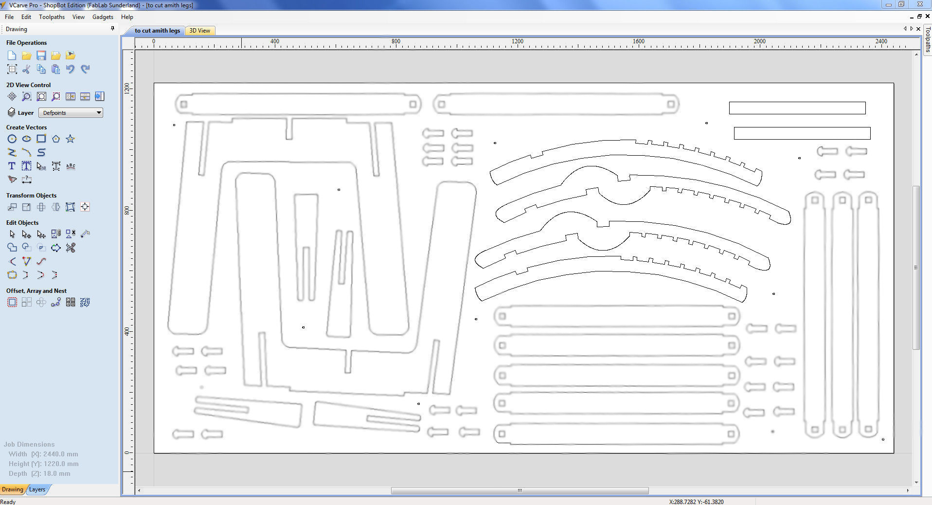
The DXF files were then imported into the V-Carve software so as to generate the toolpaths and G-Code. As i had to use plywood sheets of two different thickness, the job was combined with fellow student Amit's and Abhilash's cutting job so as to save material by utilising the vacant space available in the full sized plywood sheet.
Below is the V-Carve layout of the different parts to be cut in 18mm thick plywood. (Vertical frame, horizontal frame and the big connector). The parts of Amit has been blurred out in the image using GIMP.
After the layout was fixed, the toolpath for profile (cut) was to be created. It was observed that some of the vector paths were not closed and the same were closed using the option in V-carve. The tabs were inserted at the needed places manually and below is the screenshot after insertion of tabs.
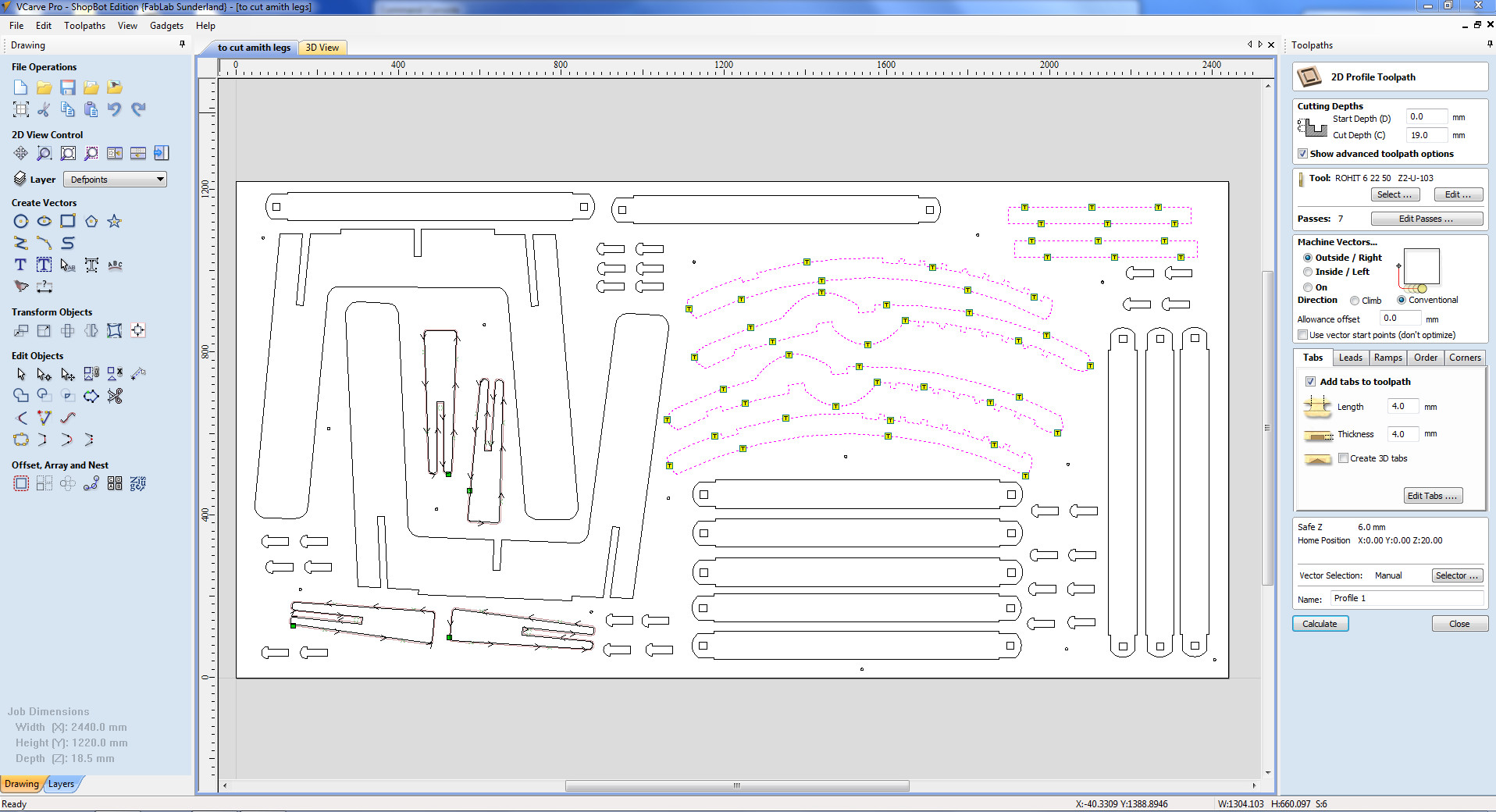
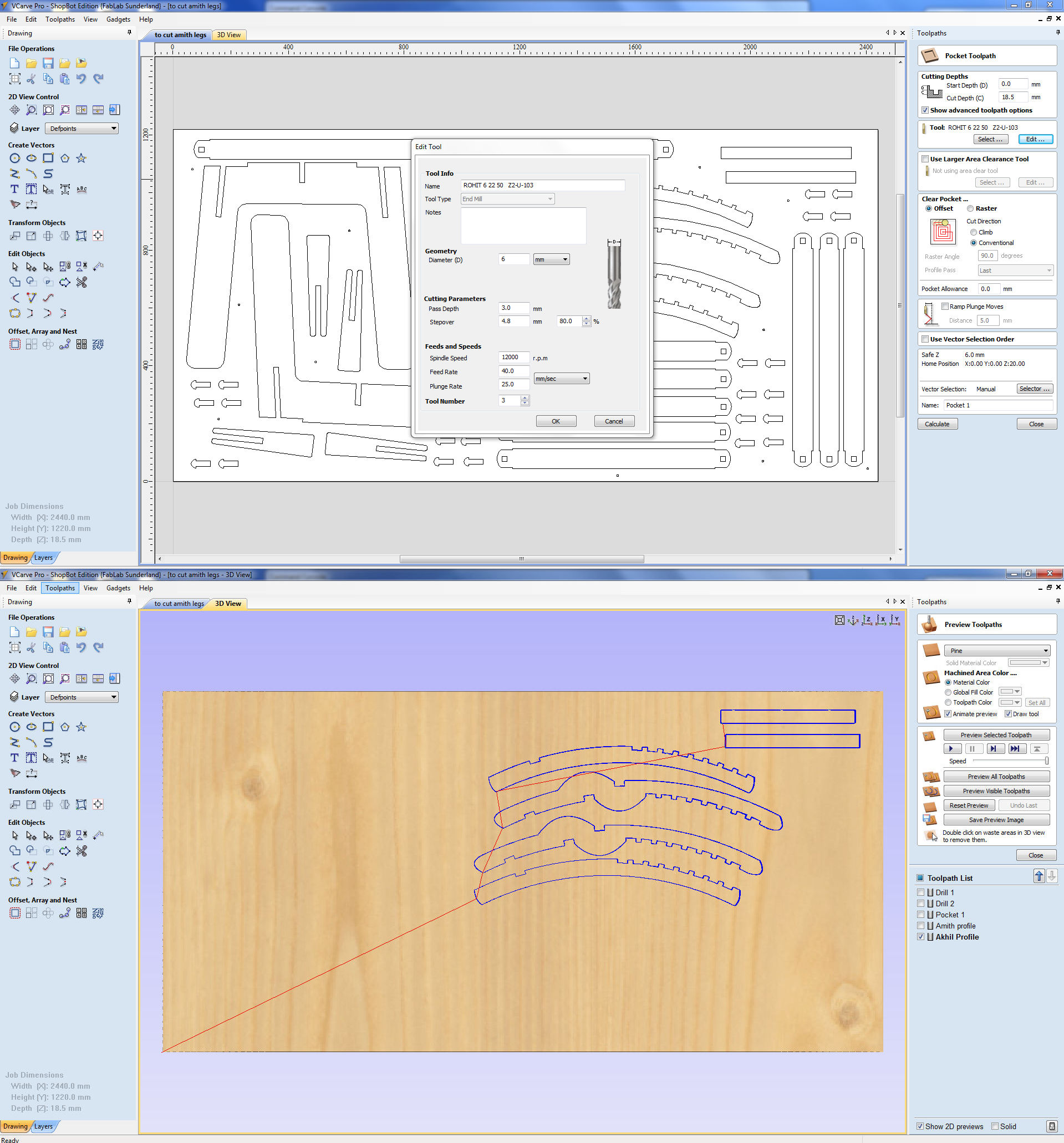
The G-Code for the toolpath was created after selecting the tool and the cutting parameters. The configuration used and the toolpath is shown below.
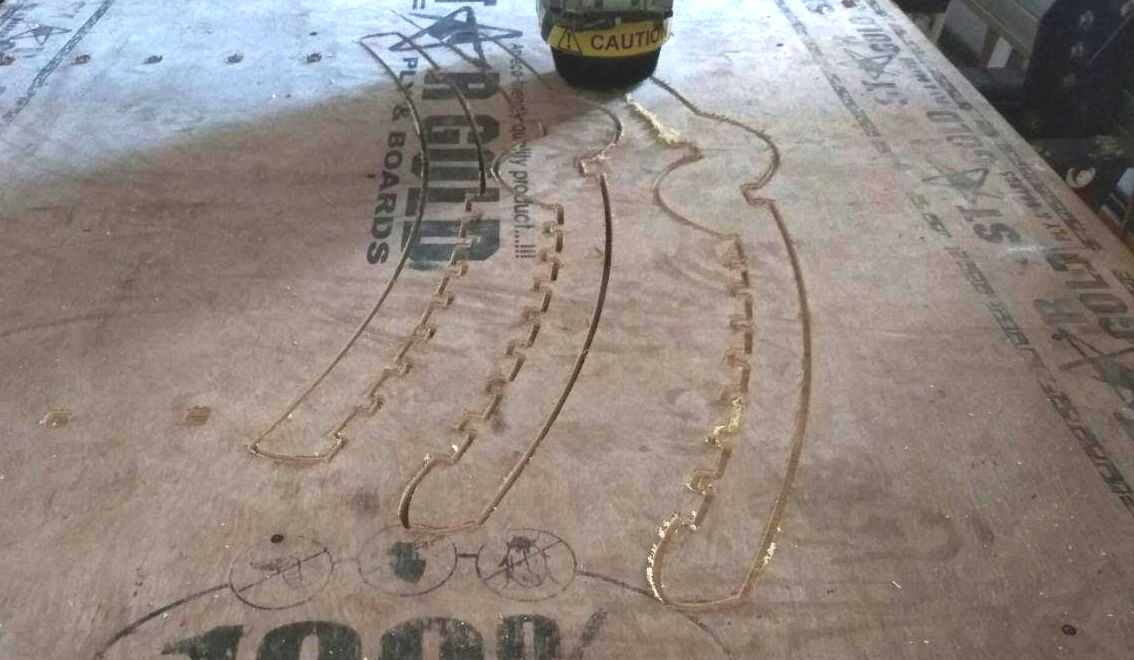
The G-Code was then opened in the command console to begin the cutting. The below image shows the cutting of 18mm plywood in progress.
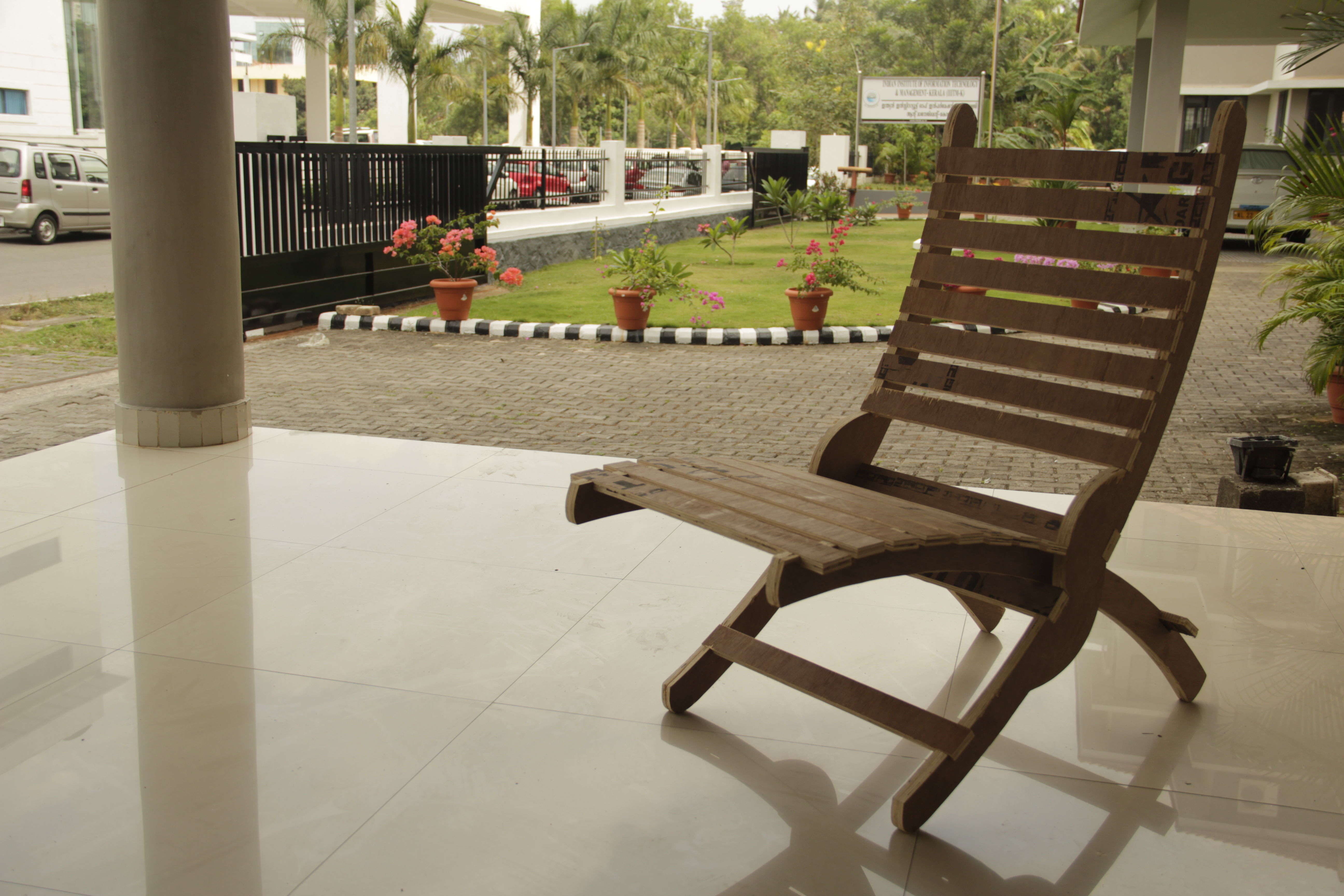
After finishing the cutting operation, the tabs were broken and the individual parts were removed from the parent material. The parts were having rough edges and were made smooth by sanding, after which the parts were assembled together to make the chair.
Errors Commiitted
The dog bones were not inserted into the layout before the generation of G-Code and the parts were not seating properly. The corners of all the slot had to be filed down manually which was a tedious process.