Week 12
Input Devices
This week's individual assignment was to design a microcontroller board which will read data from a sensor. The group assignment is to measure the analog levels and digital signals in an input device.
Hall Effect Sensor
A Hall effect sensor is a transducer that varies its output voltage in response to a magnetic field. Hall effect sensors are used for proximity switching, positioning, speed detection, and current sensing applications. Below is the datasheet of the sensor we have at our lab.
Hall Effect Sensor Working Principle
This website gave a good insight into the working of Hall effect sensors and the below image obtained from the website summarises the working.
Hall Effect Sensors consist basically of a thin piece of rectangular p-type semiconductor material such as gallium arsenide (GaAs), indium antimonide (InSb) or indium arsenide (InAs) passing a continuous current through itself. When the device is placed within a magnetic field, the magnetic flux lines exert a force on the semiconductor material which deflects the charge carriers, electrons and holes, to either side of the semiconductor slab. This movement of charge carriers is a result of the magnetic force they experience passing through the semiconductor material.
As these electrons and holes move side wards a potential difference is produced between the two sides of the semiconductor material by the build-up of these charge carriers. Then the movement of electrons through the semiconductor material is affected by the presence of an external magnetic field which is at right angles to it and this effect is greater in a flat rectangular shaped material.
The effect of generating a measurable voltage by using a magnetic field is called the Hall Effect after Edwin Hall who discovered it back in the 1870’s with the basic physical principle underlying the Hall effect being Lorentz force. To generate a potential difference across the device the magnetic flux lines must be perpendicular to the flow of current and be of the correct polarity, generally a south pole.
A schematic representation of the working can be observed below where in a wheel containing two magnets is passing by a Hall effect sensor.
The above animation was obtained from Wikipedia and is licensed under CC BY-SA 3.0
PCB Design & Production
I relied upon neil's design to design the board using the skills developed during the Electronics Design Week.
I started with adding the respective components into the schematic of EAGLE. The components added and the respective packeges are as follows.
1. ATTINY45SI (ATTINY45) (Package:SOIC8, Library: fab)
2. Resistor - RES-US1206FAB (RES-US) (Package:R1206FAB, Library: fab).
3. PINHD-2X3-SMD (Package:2X03SMD, Library: fab)
4. FTDI-SMD-HEADER (Package:1X06SMD, Library:fab
5. CAP-UNPOLARIZEDFAB (CAPACITOR) (Package:C1206FAB, Library: fab)
6. A1323LH (A13*?) (HALL EFFECT SENSOR) (Package:SOT23-W (Version 1), Library: allegro (Version 1)
I couldnt find the exact component for the hall effect sensor A1324 and hence i added an almost similar component which has the same package of SOT23-W which has got the same footprint. Below is the schematic after adding all the components and making the electrical connections.
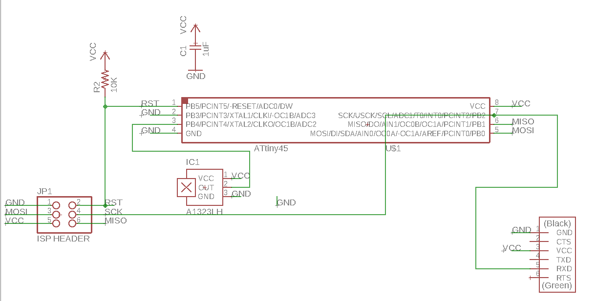
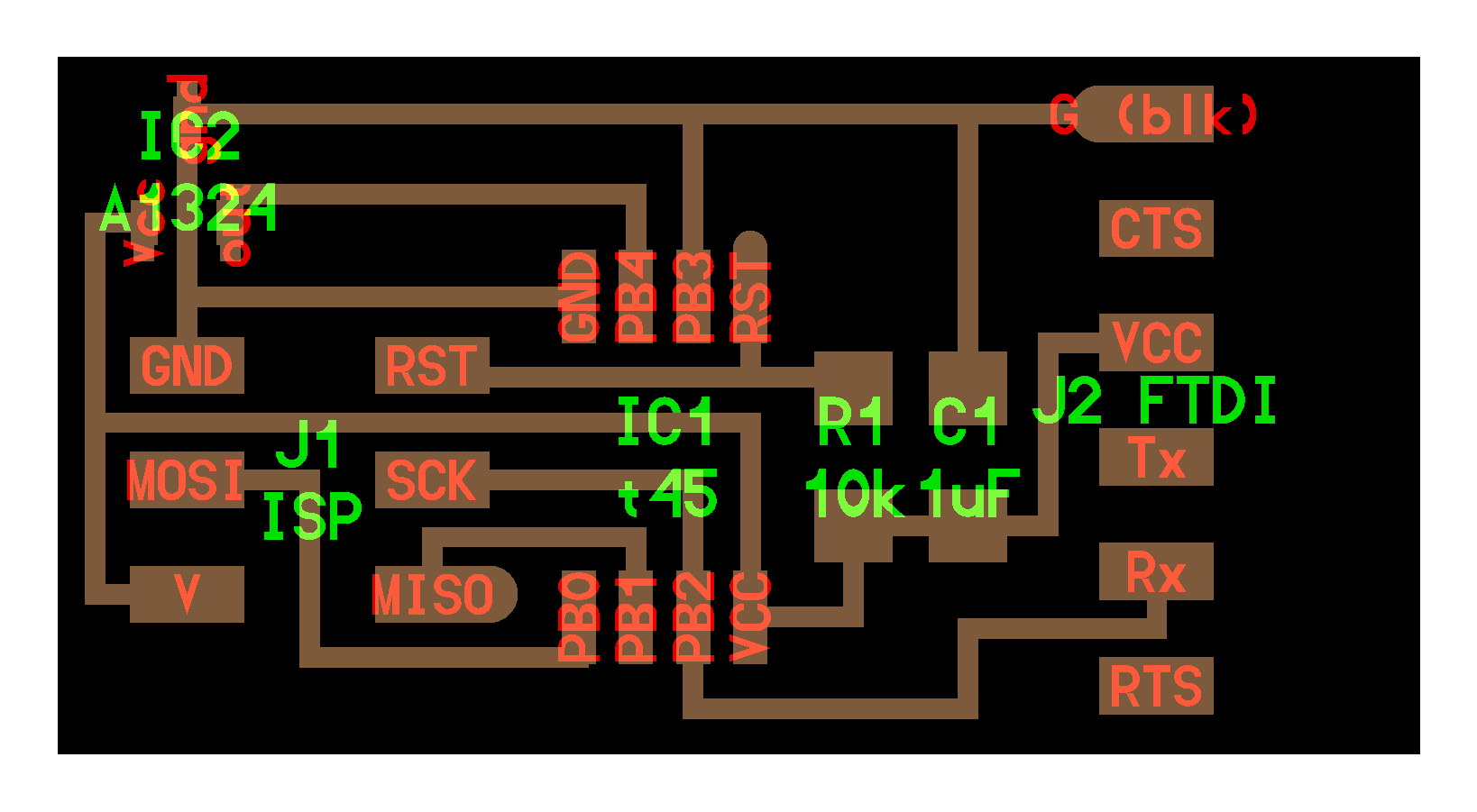
The electrical rules check were done in the schematic and the board was designed in EAGLE and below is the screenshot of the board.
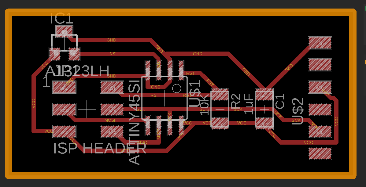
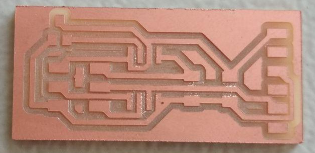
After checking for design rules, the png images of the traces and outline were exported and the board was milled and cut in Rolland MDX-20. Below is the finished board ready for receiving the components. (Electronics Production during week 5)
Click here to download the Design Files
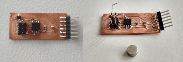
Below is the image of the board after stuffing the components. The neodymium magnet can also be seen in the image. For connecting the output of the hall effect sensor to the osciloscope, i soldered a header pin onto the trace coming out from the output pin of the hall effect sensor. After working with it for a while, the header pin started to shake and came off by damaging the traces. The damage was irrepairable and i had to manually connect the output pin of the sensor to the microcontroller pin using a wire.
Measuring Signals
Osciloscope & Signal Generator (Power Supply)
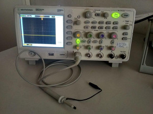
Osciloscope is a type of electronic test instrument that allows observation of varying signal voltages, usually as a two-dimensional plot of one or more signals as a function of time. Below is the image of one of the osciloscope available at our lab.
A signal generator is an electronic device that generates repeating or non-repeating electronic signals in either the analog or the digital domain. The one we have at our lab can generate signals in two channels simultaneously.
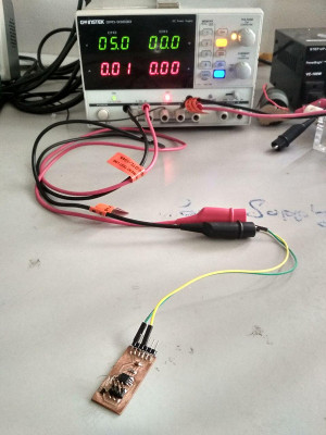
The signal generator can be used for powering up the PCB, so that we can measure the signals from the hall effect sensors during operation. Below image shows the PCB being powered up by the power supply by connecting the channel 2. The voltage was set to 5V.
Using an Osciloscope
For measuring the output signal from the hall effect sensor, the board was powered up with 5V and the osciloscope was connected across the output pin of the hall effect sensor and ground. By adjusting the settings, the osciloscope was set to display the maximum voltage. Below video shows the measuring operation being carried out.
It was observed that, the hall effect sensor gave an output voltage of approximately 2.5V when no magnetci field is present. The output Voltage gradually increased to 5V, when the south pole of the magnet was gradually brought near the sensor. The voltage gradually decreased to approximately 0V when the north pole of the magnet was gradually brought near.
For measuring the output signal from the PIR sensor, the PIR sensor was powered up with 5V and the osciloscope was connected across the output pin of the PIR sensor and ground. By adjusting the settings, the osciloscope was set to display the maximum voltage. Below video shows the measuring operation being carried out.
It was observed that, the PIR sensor gave an output voltage of 3.3V when motion was detected and in the other case there was no output voltage.
Programming & Testing the PCB
Using the learnings from Embedded Programming Week, Arduino IDE was used to programme the microcontroller to read the data from the sensor and to send it serially. First step was to identify the type and range of the data being read by the microcontroller. To display the serial monitor of Arduino IDE, click Tools > Serial Monitor. It will open a new window which displays serial data send by the micro controller.
To read the value of the ADC pin of the microcontroller while in operation, the board was programmed to send serial data using the following, which can be observed in the serial monitor window of the arduino.
First we have to set up the Arduino to read serial data. For that, include the serial library and declare the RXD and TXD pin of the microcontroller.
The arduino Pin numbers for ATtiny 45 was obtained from this image.
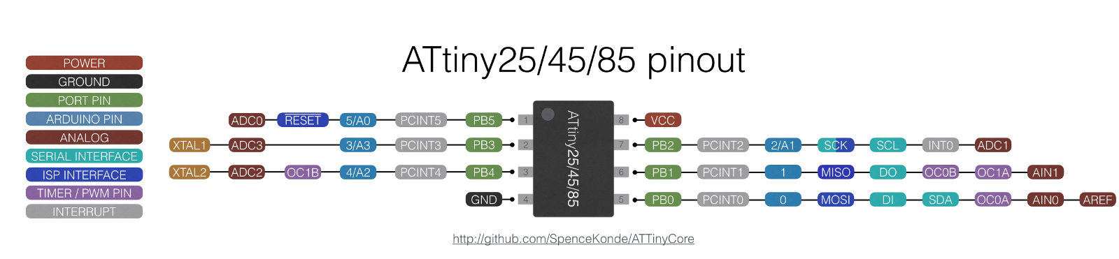
In this case, PB2 was the transmitter pin of the microcontroller, which is Pin 2/A1 in arduino. Since, no serial data was sent to the microcontroller, i used a dummy pin PB1, which was left unused.
  // This program is written to serially print the values read from a Hall Effect Sensor.
  // Akhil Hari 24-06-2018
  // Fab Academy 2018, Fab Lab Trivandrum, India
  // Input Devices Week

  // MCU - ATTINY45SI
  // Output of Hall effect sensor(A1324) is connnected to PB4 (Arduino Pin No. A2).
  // Since, ATtiny 45 doesnt have a hardware serial pin, we have to declare and initialise the serials pins in the software.
  // PB2(Arduino Pin No. A1) is connected to the RXD pin of FTDI connector.
  // PB1(Arduino Pin No. 1) is connected to MISO of ISP Header.

  #include <SoftwareSerial.h>     // Includes the library for software serial.
  SoftwareSerial serial(1, A1);   // Declares the (RX, TX). RX declared as 1 is a dummy. Change the value to the corresponding Arduino Pin No.
  void setup() {
    serial.begin(9600);           // Begins serial communication at a baud rate of 9600.
  }

  void loop() {
    int x = analogRead(A2);       // Reads the value of pin A2 which is connected to the sensor and stores as an integer x.
    serial.println(x);            // Prints the value of A2, in the next line of the serial monitor.
    delay(1000);                  // Delay of 1s between the readings.

  }
From the serial monitor of the Arduino IDE it was observed that, in the absence of a magnetic field, a value of 512 was being send by the microcontroller. When the south pole was gradually brought near the sensor, the value increased and it decreased when the north pole was brought near. The same can be observed from the video below.
From the observed value, i modified the Arduino code such that the microcontroller will send serial data specifying the polarity of the magnetic field. Below is the final code.
  // This program is written to detect a magnet's pole and to print it serially by using values read from a Hall Effect Sensor.
  // Akhil Hari 24-06-2018
  // Fab Academy 2018, Fab Lab Trivandrum, India
  // Input Devices Week

  // MCU - ATTINY45SI
  // Output of Hall effect sensor (A1324) is connnected to PB4 (Arduino Pin No. A2).
  // Since, ATtiny 45 doesnt have a hardware serial pin, we have to initilise the serials pins in the software.
  // PB2(Arduino Pin No. A1) is connected to the RXD pin of FTDI connector.
  // PB1(Arduino Pin No. 1) is connected to MISO of ISP Header.

  #include <SoftwareSerial.h>
  SoftwareSerial serial(1, A1);
  void setup() {
    serial.begin(9600);
  }

  void loop() {
    int x = analogRead(A2);
    if (x > 514)                  // The analog value at PB4 when no magnet is present near the hall effect sensor is 512.
    {                             // The value increases from 512 if south pole is brought and the opposite with north pole.
      serial.print("South Pole"); // An offset of 2 is used in the value to isolate noises from being read as magnetic presence.
      delay(200);
      serial.println(x);
    }
    else if (x < 510)
    {
      serial.print("North Pole");
      delay(300);
      serial.println(x);
    }
    else
    {
      serial.println("No magnetic Field");
      delay(300);
    }
  }