Week 6
3D Scanning & Printing
This week's assignment was to test the design rules for the 3D printer available at our lab and to design and 3D print an object that could not be made subtractively and also to 3D scan an object (and optionally print it)
3D Printing - Working Principle & Design Rules
3D printing is an additive manufacturing method in which thin layers of thermoplastic filament is successively fused and deposited at defined cordinates. This is known as Fused Deposition Modelling (FDM) or the Fused Filament Fabrication (FFF). Thermoplastic when heated becomes soft and regain hardness when cooled. The heated thermosplastic is forced out through a nozzle and is deposited in layers to make the final object. 3D printers are primarily used for the rapid prototyping of deisgns and concepts. With a properly calculated design, and with the use of appropriate materials, it can be also used to make critical parts of professional devices. 3D printing stands apart from other manufacturing processes in the manufacturing of single piece parts that cant be made subtractively. The 3D printers available at our lab are "ULTIMAKER 2" and "DIMENSION sst 1200es".
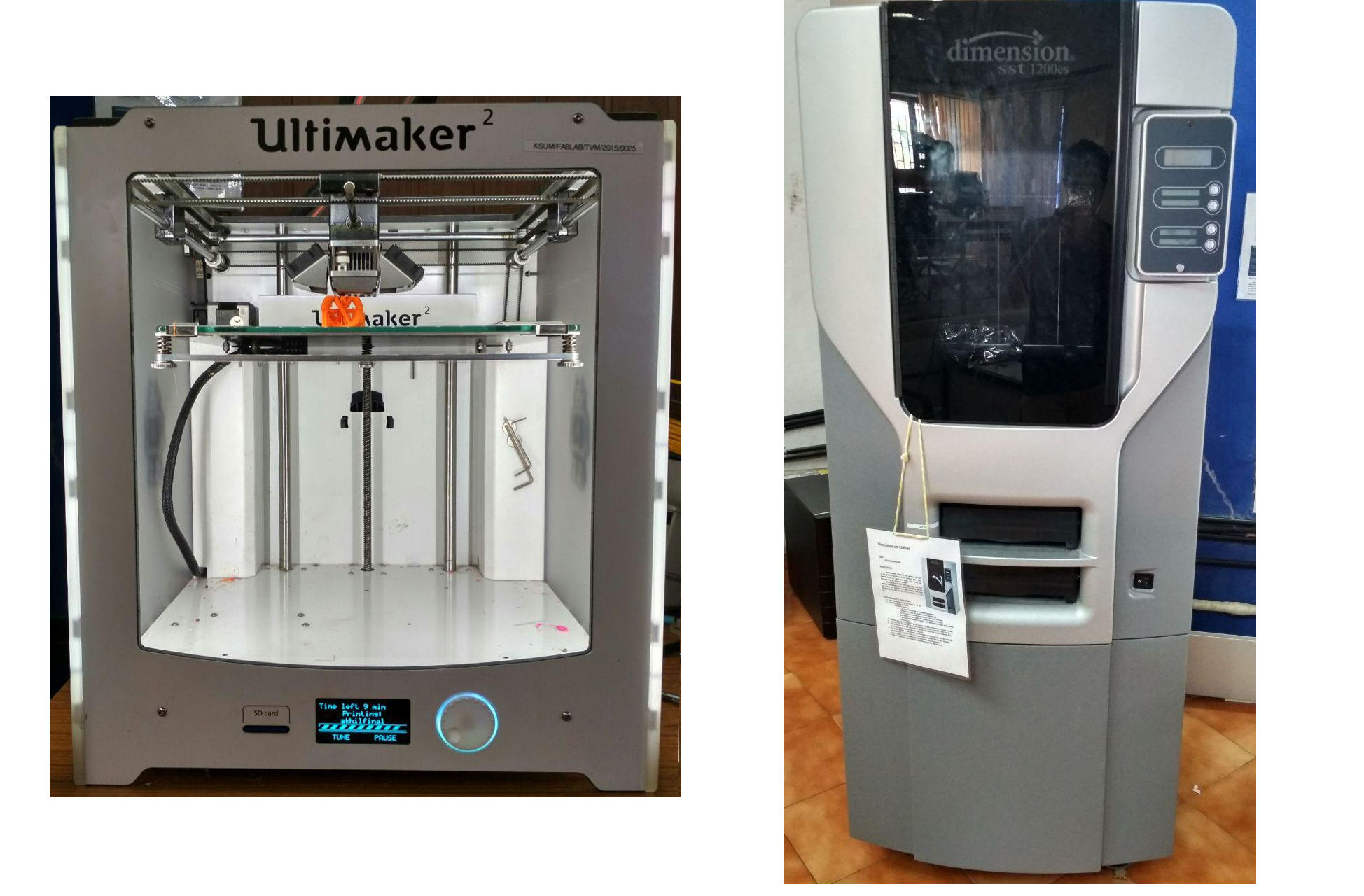
ULTIMAKER 2: Driven by two motors, the nozzle can moves in the X & Y directions along the guide rails. A third motor moves the buildplate in the Z direction making it possible to print 3D objects. Another motor near the filament spool at the rear side pushes the material into the nozzle. The melting temperature for each material is different and is to be set accordingly in the machine by setting the temperature of nozzle. The temperature of build plate have to be set accordingly to avoid colling of the material during the printing. There are colling fans around the nozzle which cools down the thermoplastic as soon as it is fused and deposited. The suppports for the object is also printed using the same material and have to be manually removed. The ultimaker2 can print three different materials, namely the ABS(Acrylonitrile butadiene styrene),PLA (Polylactic Acid), and the CPE (Copolyester).
DIMENSION sst 1200es: is a professional quality printer which can print only ABS (Acylonitrile Butadiene Styrene). It uses seperate support material for the object which can be removed by immsersing the printed object in a heated solution for 24 hours.
Design Considerations
The object has to be designed in a 3D software and has to be exported as an STL file. The STL file has to be then imported into the bundled software of the 3D printer (Cura in case of Ultimaker 2) for generating the G-Code. The printer will print the object in accordance with the G-Code. There are several parameters to be considered during the design and also during the generation of G-Code.
1. Material
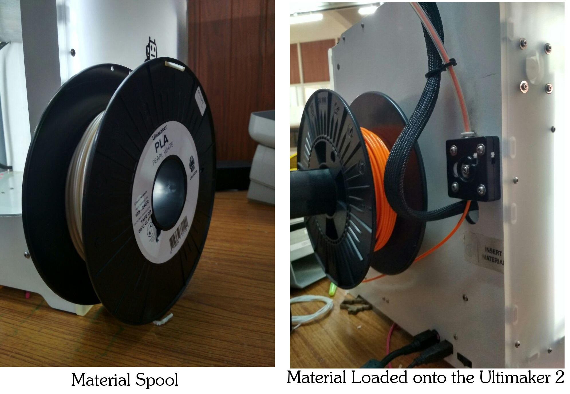
PLA is made from organic material and is biodegradable at controlled environments. In terms of overall strength, ABS slightly outperforms the PLA. ABS is non biodegradable and is used for professional applications like electronic housings etc for its high ductility and machinability after printing. PLA has a lower printing temperature when compared to ABS and is less likely to warp when compared with ABS. The material filament comes in spools.
2. Size & Orientation of the Final Object
The size of the final object has to be kept well within the build volume of the 3D printer. The object has to be scaled down, if the design file is greater than the build volume of the printer.
The bundled software while generating the G-Code, considers the supports needed for making the object stable during the printing operation. The orientation of the design is to be selected such that only the least support is generated during the printing operation. The same can be verified by selecting "Layer" view in the Cura software.
3. Layer Height
The height of each layer deposited can be defined in the bundled software before generating the G-Code. Lesser the layer height, more is the quality and finish of the print and also the time taken to print.
4. Shell Thickness
Even if the object designed in the 3D software is a solid one, the density inside the object can be reduced, while keeping full density for the outer shell of the object. The thickness of the outer shell can be adjusted in the software according to the structural purpose of the object. The shell thickness specified during the generation of G-Code will be uniformly applied to every part/projection of the object.
5. Retraction
This parameter defines the flow of the material through the nozzle while the nozzle moves between discontinuos points in the object. When retraction is enabled, the material will be pulled inside the nozzle while the nozzle moves between two points. If not enabled, the nozzle will continously eject the molten material out, leaving a fine line of material along the path travelled. Enabling retraction can compromise the quality of the print for the material will experience a delay while coming out through the nozzle leaving small pits and peaks in the deposited layers.
6. Bottom/Top thickness of the Fill
This parameter defines the thickness of the bottom and top most part of the object. Similar to the shell thickness, it can affect the strength of the printed object. In between the top and bottom layer, the density of the object can be reduced.
7. Fill Density
This defines the density of the print inside the obejct. By varying this parameter, the density of print can be adjusted. This will not affect the density of the outer layer. By reducing the fill density, considerable savings in the consumption of material can be attained, however it compromises the overall strength of the final object. The fill density has to be selected keeping in mind of the structural application of the object.
7. Print Speed
This defines the speed of the horizontal movement of the nozzle from one point to the other. Lesser print speed will increase the quality of the print but will take more time.
8. Support Type
Almost of the designed object which are to be 3D printed will need suppports at some places or the other. The nozzle will deposit the material in layers, and in the absence of a proper support, the material coming out from the nozzle will fall down due to gravity, making the entire job useless. In order to keep the molten material at the intended place, supports are to be provided. The supports will be printed along with the object and has to be removed after the printing operation is finished. The support can be given "everywhere" or just from the "buildplate". If the support selected is "everywhere", the software will generate the supports at all the necessary points. In this case, the supports will be provided from the buildplate and also from the object itself. If the support type selected is "buildplate", supports will be generated only from the buildplate. The supports are to be removed from the object after the printing job is completed.
9. Platform adhesion type
During the printing operation, the object has to be held firmly to the build plate. For acheiving the same, the software will generate a foundation like structure for the object. The machine will begin by first printing this foundation upon which the printing of the obejct will be carried out. This foundation has to be removed from the object after the completion of the printing operation. There are two types of support namely "brim" and "raft". If the option selected is "Brim", the machine will create a thin layer of material to act as the adhesion platform. This type of platform adhesion is the generally used one. If the option selected is "Raft", a thick layer of material will be deposited by the machine atop which the object will be printed. This type of platform adhesion is required for tall objects and for objects which has comparitively less cross sectional area at the bottom most part.
10. Support Material & Removal of supports
The support is printed along with the model and is to be removed after the printing operation is finished. The Ultimaker2 uses a single material to print the object and the supports and hence the supports are to be manually removed from the object. DIMENSION sst 1200es uses a different support material which is soluble and can be easily removed by immersing the printed object in a chemical solution.
Testing the 3D Printer
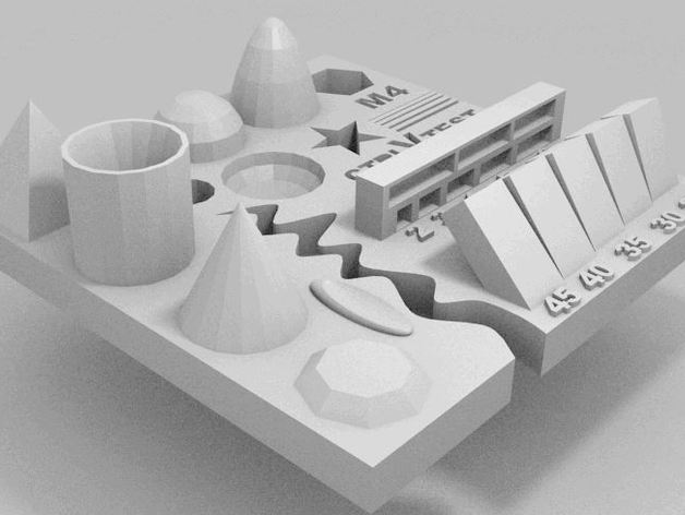
Test your 3D printer! by ctrlV is licensed under the Creative Commons - Attribution - No Derivatives license
The STL file of the above model was downloaded from www.thingiverse.com to test our 3D printers by printing with a Nozzle Diameter of 0.4mm,"Brim" type plaform Adhesion and with no supports. Layer Height of 0.08mm, Shell Thickness of 0.8mm, Bottom/Top Thickness of 0.8mm, 35% Fill Density and 50mm/s print Speed was set in Cura software which showed 1Hr and 54Min to print. The nozzle temperature was set to 240 degree celcius and base plate temperature was set as 80 degree celcius. Below image shows the printed object.
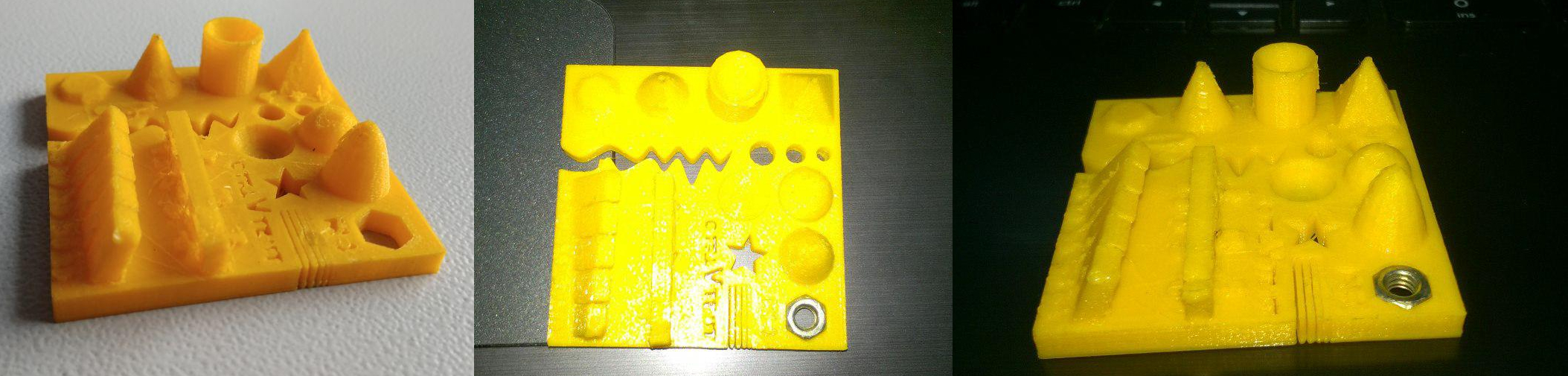 Upon observing the result, the diameter of holes were slightly less.
The M4 nut was fitting perfectly, with the pyramid and cone having good surface finish.
Bridges didnt came out well without the supports.
Upon observing the result, the diameter of holes were slightly less.
The M4 nut was fitting perfectly, with the pyramid and cone having good surface finish.
Bridges didnt came out well without the supports.
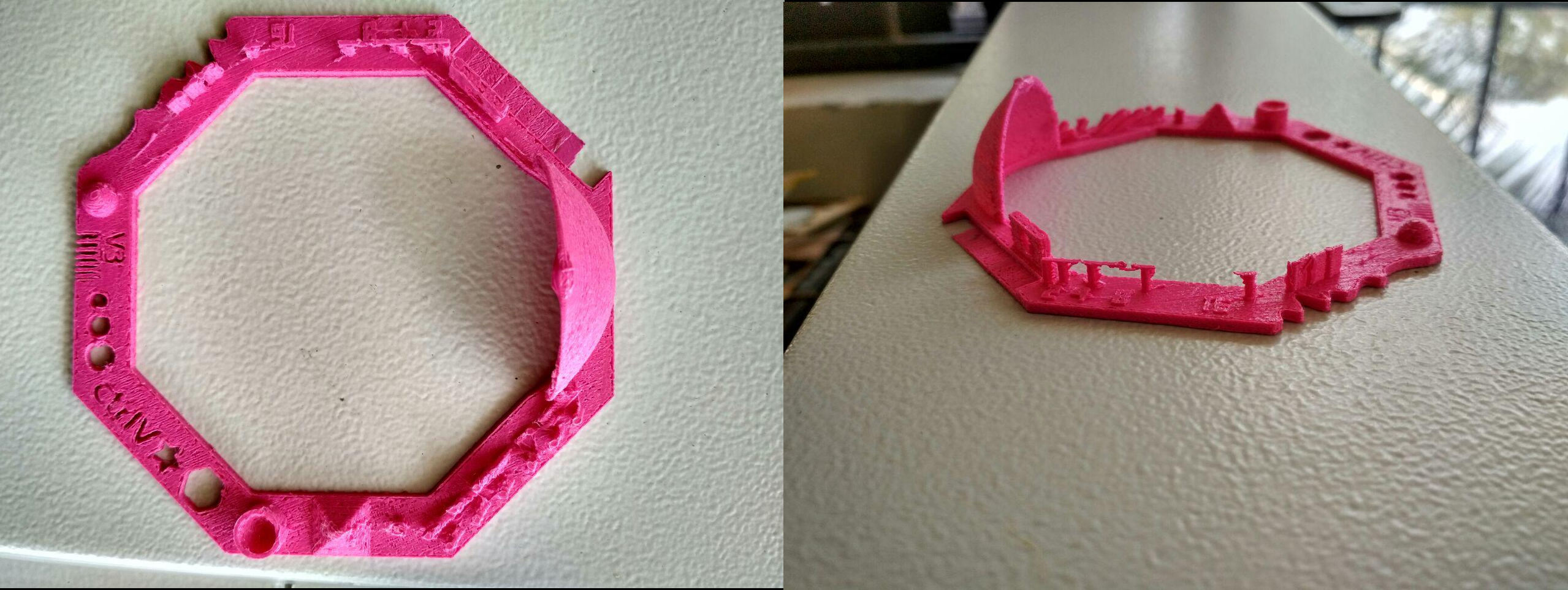
We also tested with another test file obtained from this website. The below image is the result of our second test.
Designing and 3D Printing an object
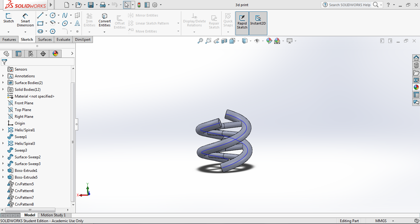
The design skills developed during the Computer Aided Design week and the Computer Controlled Cuting week was put to use in designing a double helical structure similar to the DNA in SolidWorks by following this tutorial. The double helix along with the connected link forms a very complex shape, making the inner portions of the object inaccessible to the cutting tool of a CNC machine and making the entire object itself impossible to be produced using a subtractive method.
To design the DNA structure, two helix were drawn to begin from a circle, with its rotation 180 degrees apart with one helix in the clockwise direction and the other in the anticlockwise direction. The tutorial was entirely followed step by step to make the below design.
Click to download the design files
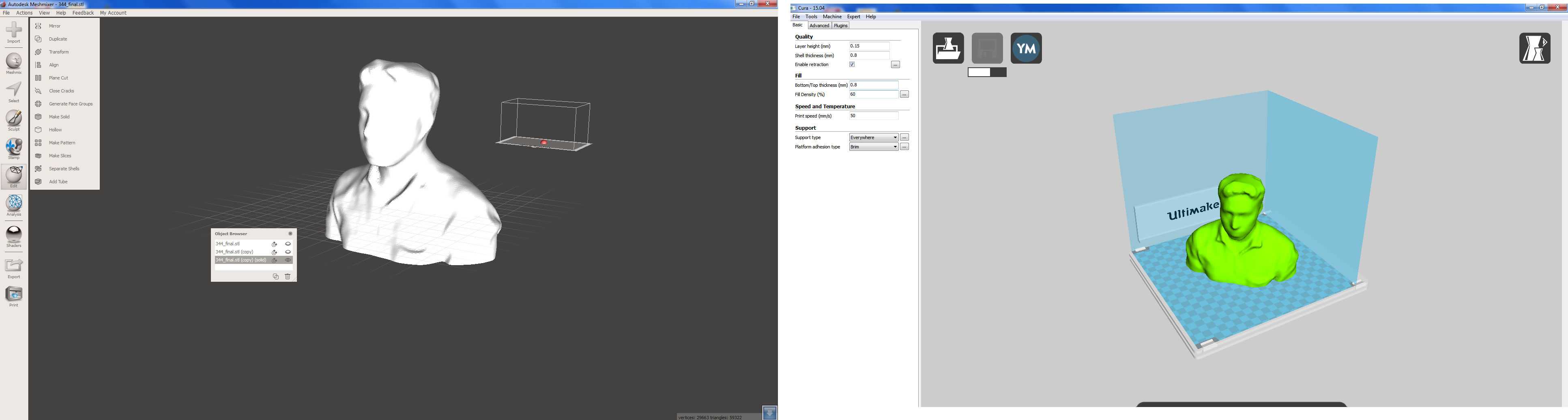
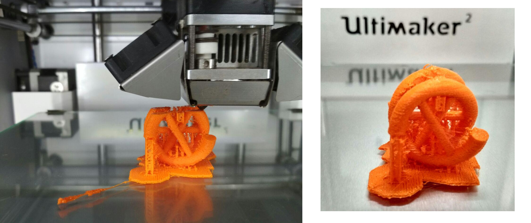
The STL file was imported into CURA software and the below image shows the "Layer View" in CURA software. By sliding the slider on the right side, we can see how the object and supports will be printed. Support was unavoidable and to reduce the supports, the object was placed in the below manner.
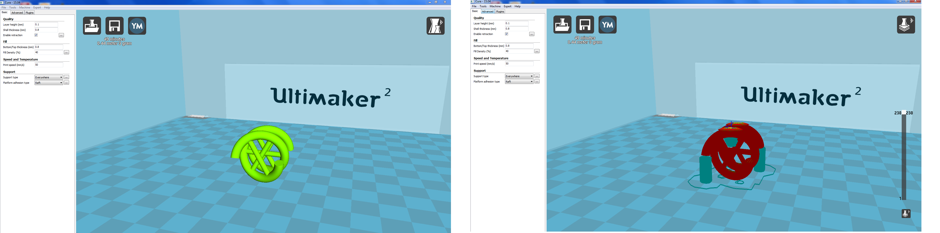
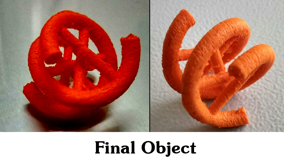
The layer height was selected as 0.15mm, shell thickness as 0.8mm, fill density of 40% and a print speed of 50mm/s was set in CURA software and the G-Code was generated. The platform adhesion type selected was "Raft" and supports were generated everywhere. The below image shows the printing in operation and the finished print.
The supports were manually removed and took a great effort and time. The object felt robust and strong but lacked surface finish. The layer height was clearly visible for the layer thickness selected was 0.15mm.
3D Printing for the Final Project
3D Printing for the Machine Week
Problems Encountered & Errors Committed
1. Incorrect selection of platform adhesion type: On my first attempt to 3D print, the platform adhesion type selected was "Brim". After completing about 20%, the object was seen shaking due to the lack of the platform adhesion. Due to this, the material coming out through the nozzle was not being deposited at the right place and the print was cancelled. This happened since the cross sectional area of the object at the bottom part was very less and this area had to support the entire object which made the entire object to shake during the printing operation. In the second attempt, the support type was selected as "raft" and the print came out perfect.
2. Difficulty in removing supports: Removal of the support material at the inner portions of the object was a bit difficult. Also, the "raft" platform adhesion had left an impression on the object which had to be filed down.
3. Poor surface finish: The selected layer height of 0.15 mm is the reason for the same. For high quality print the layer height should not be more than 0.1mm.
3D Scanning
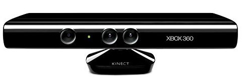
A Microsoft Kinect sensor (primarily designed to work with XBOX 360 gaming console) is what we use in our lab for 3D scanning. It detects the distance to an object with the help of infrared sensors and combines it with the data obtained from the VGA camera to make a 3D scan.
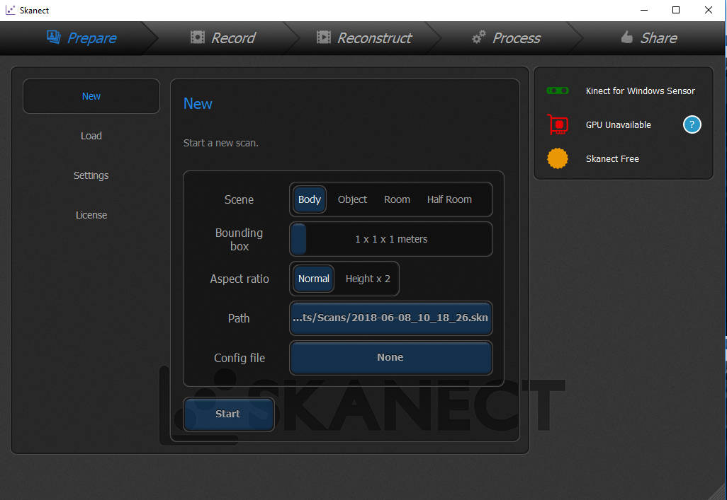
Free version of Scanect software was used to do a 3D Scan which had a limitation of 5000 faces. Below image shows the interface of the Scanect software where we can define the nature of scan and the size and aspect ratio of the bounding box to be scanned. The object to be scanned is to be placed in front of the scanner and clicking the "start" button will begin the scan. The bounding box will be also visible. The object has to be rotated at a slow pace so that the entire surface geometry could be calculated by the sensors. During the scan, the software will display green and red colours indicating the areas scanned.
For familarising with the instrument, different objects were scanned. The hand drill at our lab was scanned by placing and rotating the drill infront of the sensor at the correct distance. The below image shows the finished scan.
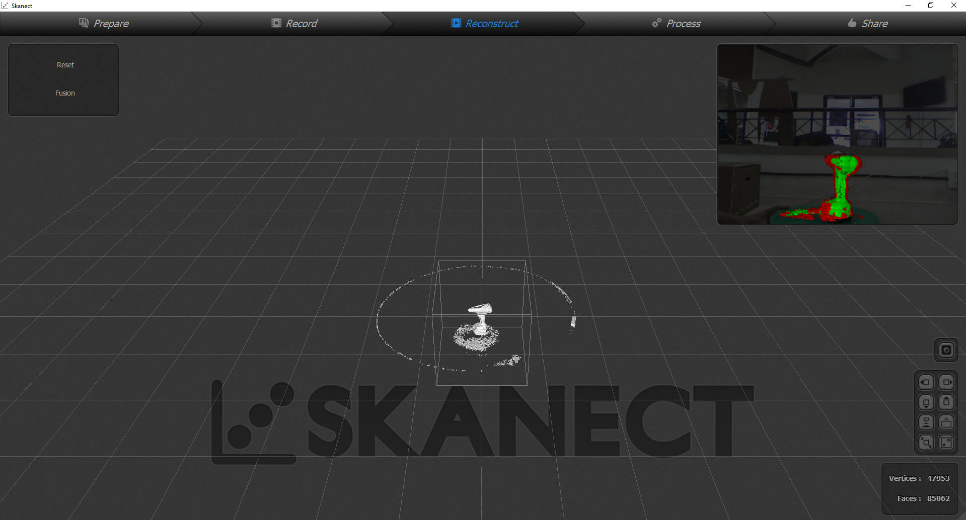
It was observed that the fine details were not present and top surface was not entirely scanned. Another attempt was made to scan a transparent bottle which turned out to be a complete failure.
After trying out several objects, i tried to scan myself. The scanner was placed atop a table and made stationary with me sitting over a revolving chair. By revolving at a slow pace the scan was completed. However, as with the case of the hand drill, the top surface of the head was not scanned and the surface was seen with holes. The below image shows scanned file opened in Autodesk Meshmixer software.
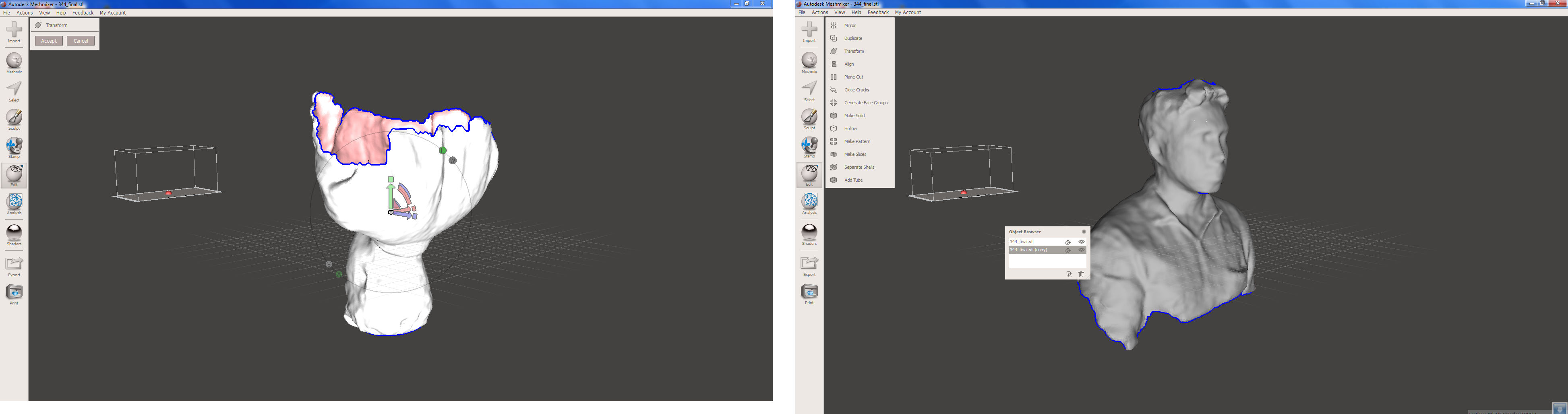
The surface was turned into a solid object and the broken mesh were joined to form a smooth surface. The object was then cut along a plane and the STL file was exported and opened in CURA software.