In this week, I learned how to fabricate with CNC machine. I designed a stool and manufactured it with the CNC machine.
Assignment
- Make something big (on a CNC machine).
computer-controlled machining
In this week, I learned how to fabricate with CNC machine. I designed a stool and manufactured it with the CNC machine.
I designed a stool to use in FabLab with Fusion 360. I used OSB (Oriented Standard Board) which thickness is 11mm. First I set parameters, such as material thickness, width, length and height. I started sketch. I drew a rectangle and made the corners curve using Fillet function (Sketch> Fillet). 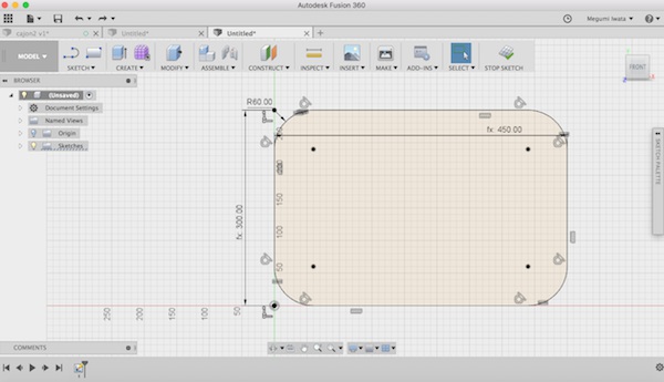
I stopped sketch and extruded the surface as material thickness. 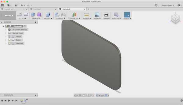
I went back to sketch and designed letters: FAB which were going to be used as legs of the stool. I drew lines of shapes of the letters and deleted lines which crossed each other with Trim function (Sketch> Trim). I stopped sketch and extruded the letters. 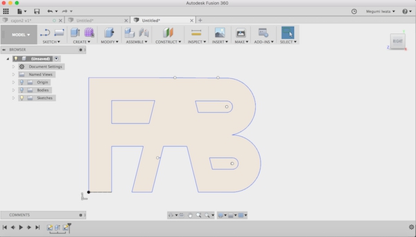
Next I made a joint tab on the leg and slots on the top. In sketch mode, I drew construction point in the middle of the leg on the top edge of the surface. I drew a rectangle which centre was on the construction point. I stopped sketch and extruded the tab with distance of the material thickness. I got the tab which height is the half of the material thickness on the top surface of the leg. 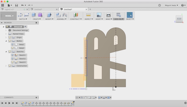
I created mid plane between edges of the top board (Construct> Midplane). I mirrored the leg on the mid plane (Create> Mirror). I selected the surface of the top board and started sketch. I drew a rectangle of the same size with the tab and placed it near the edge. 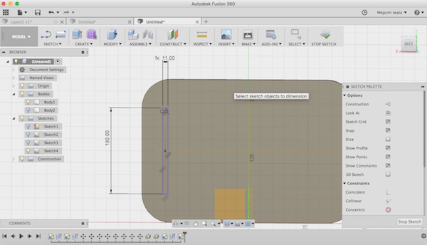
The CNC machine has limitation that it cannot make 90 degrees corner. When the bit cuts the inside of the corner, since it is spinning, it makes a circular corner instead of a straight 90 degrees corner. For this reason, I made a slot which corners are rounded (dogbone) so that the machine can perform correctly. I drew a circle on each corner and deleted the lines which crossed with the outline of the rectangle using Trim function.
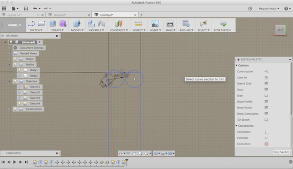
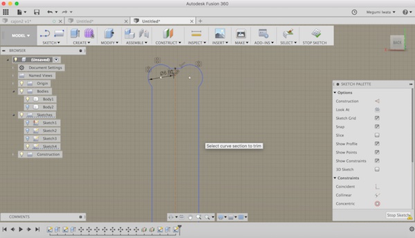
I copied and pasted it on the other side of the board. 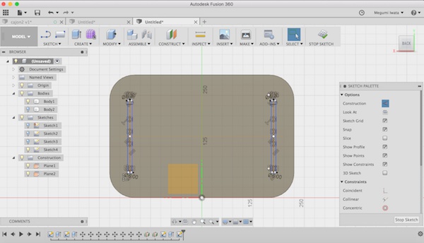
I stopped sketch and cut the dogbone slots to the half of the material thickness. 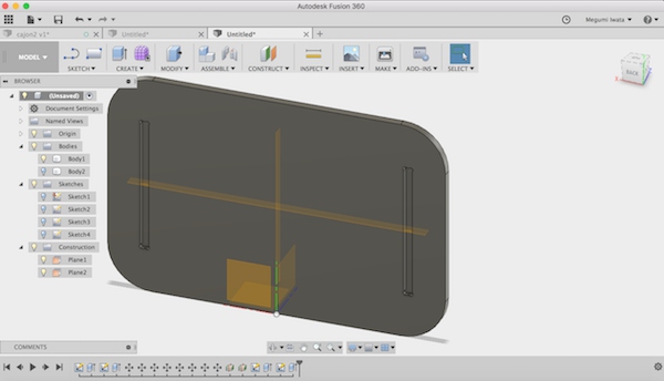
Now the stool design is ready. 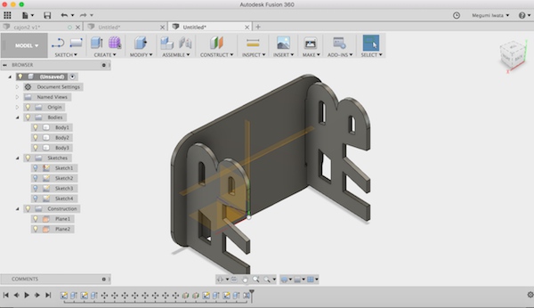
I selected all bodies and right click> Create components. So that I can move them freely by dragging. I turned the legs to the same orientation with the top board (Modify > Move/Copy) and used Align (Modify > Align) to move them to the same plane. I dragged the components and aligned. 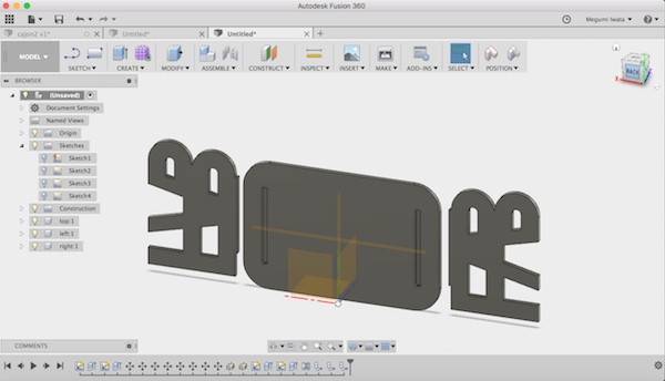
I changed the mode to CAM to create tool paths for the CNC machine operation. Before I started, I downloaded and imported tool library and FabLabNC postprocessor from Fab Lab Oulu wiki page to Fusion 360 CAM. I went to Manage> Tool library and selected Local and right click> Import tool library. I placed postprocessor file in the correct place (Macintosh HD> Users> USERNAME> Autodesk> Fusion 360 CAM> Posts). This instructions explains how to add postprocessor. Now when I select Actions> Postprocess> Source: personal post, there is an option: FabLab Oulu CNC postprocessor.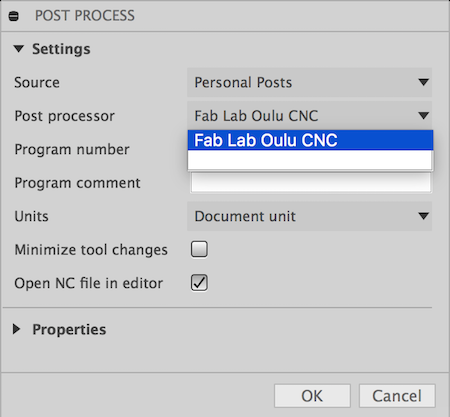
First I chose Setup> New setup. I selected Orientation> X and Y axes, Origin> Stock box point. I selected the lower left corner as origin.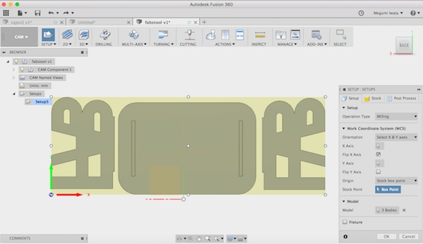
I went to Stock section, changed stock offsets as 0mm and clicked OK. 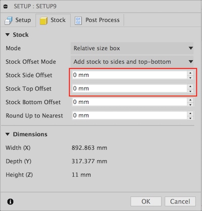
I created tool paths for pockets. I chose 2D which the machine makes each surface as a flat bottom surface instead of a curved surface. I selected 2D Pocket. In Tool section, I chose FabLab tool library I added 8mm flat bit.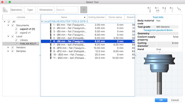
There are different types of bits. The ones which have two edges vertically to the flat bottom is suitable for milling wood. The ones which have slanted edges (upcut tools) might peel off some materials from the milled edges.
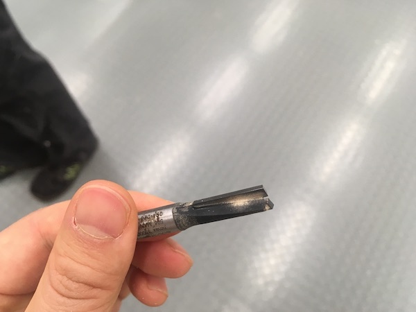
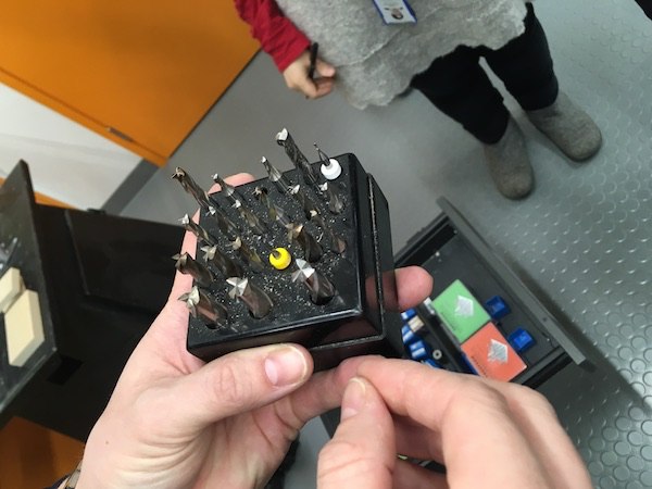
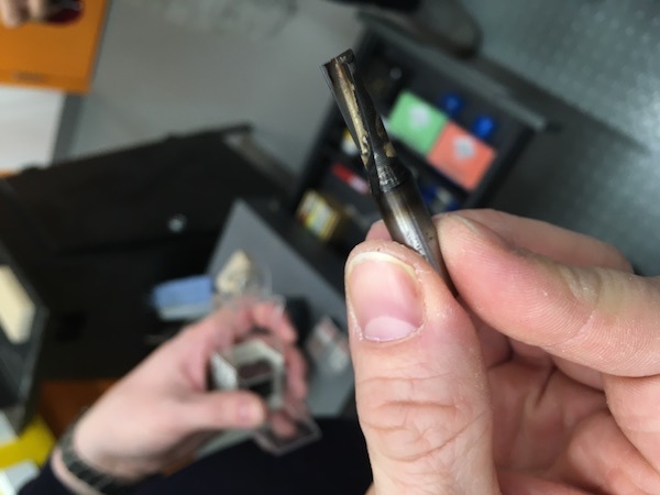
Following picture shows wood material which edge was peeled off by milling. There are several reasons that the wood material can be peeled off from the edges.

In Geometry section, I chose the faces I wanted to make pockets. 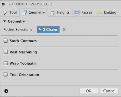
In Height section, I chose Model top as top height, and the bottom surface of the pocket as bottom height.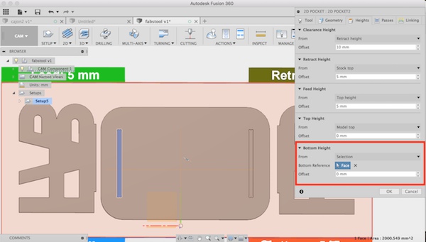
In Passes section, I selected Multiple Depth which the bit creates the depth not at once but goes multiple times till it reaches the depth. I selected 3 mm as maximum step-down and marked Use even steps. So the machine calculates how deep the bit cut out depending on material thickness and maximum depth. I also removed the mark on Stock to leave which leaves some extra material to finishing or sanding. I wanted to cut all the material up to the design so I removed the mark. 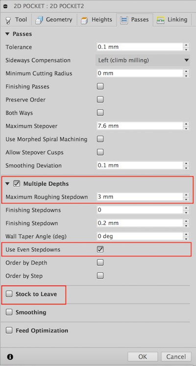
In Linking section, I removed the marks on Leads & Transitions which means the bit starts milling on the starting point which is defined in the design without any extra cut before or after. It is useful for cutting metal. Metal is hard so the bit cannot cut in the virtical way, but it cuts in horizontal way. The bit comes from outside of the metal stock (Lead-in) and mills metal in horizontal way. But I used soft material, wood, I don't needed lead-in and lead-out, so I removed these marks.
I selected Plunge as Ramp type. Plunge is like drilling, it mills from the top to the bottom. It is suitable for milling wood. However, it is not good for hard material, such as metal. It might break the tool. I clicked OK.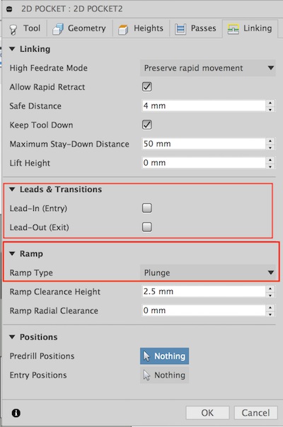
Next I made tool paths for cutting. I selected 2D> 2D contour. I used the same tool, 8mm flat. In Geometry section, I selected all the lines which I wanted to cut on the bottom surface. 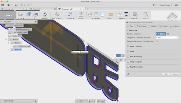
I marked Tabs to add tabs on the edges of pieces to avoid the pieces moving or small pieces flying away. It takes some effort to remove tabs. Considering both enough strength to keep object staying and less effort to remove them after contouring, I set tab width 8mm, height 2mm and distance 64mm. 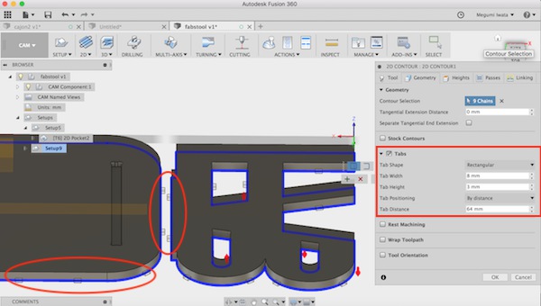
In Height section, I chose Model top as top height, and selected one face of the bottom surface as bottom height. I checked the bottom height is -11mm. 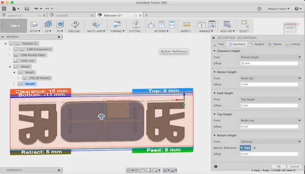
In other sections, I used the same settings as I described above. I went to Action> Simulation to see the tool paths. 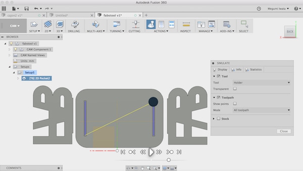
I went to Action> Post Process to convert data of the tool paths as NC code so that CNC machine can perform. I selected personal posts, FabLabCNC.cps as post processor and saved the file.
We used Rensi E2-1234 CNC router. Eino Antikainen, Fab Academy 2017 alumni, showed us how to operate the CNC machine.
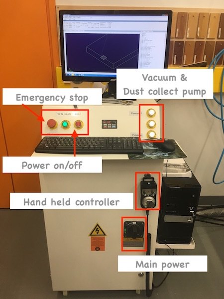
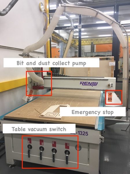
First we turned on the main switch and power on. Then we set up the table. We attached the material, OSB, on the table with screws. Make sure the screw doesn’t go down deeper than the wooded table. 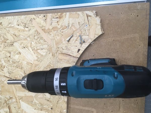
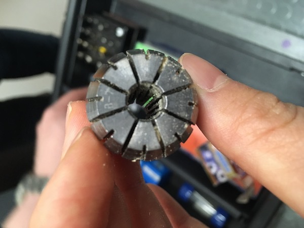
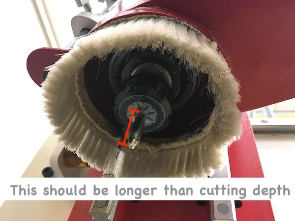
Next we set the 8mm flat bit on the bit holder and set it to the machine. Check the bit diameter and use correct holder. Note that diameter of head and bottom are different. Holder diameter need to fit with diameter of bottom of the tool. When you attach the bit on the holder, length of the bit out from the holder should be longer than cutting depth.
Next, we opened software. 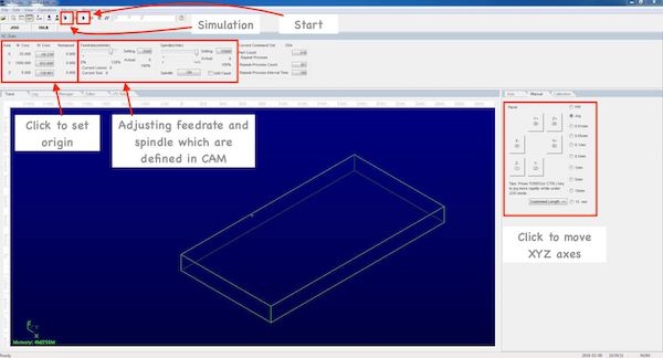
We defined the origin point. There are two ways to move the router. One way is to move the router with XYZ arrows on the screen. Pressing control key and keep pressing an arrow allow to move faster. Another way to move the router is using the hand wheel controller. In Manual section in software, choose HW to use hand wheel. We can choose XYZ and move it by rotating the dial. When the bit came to the appropriate XY position, we clicked X and Y as origin. We can adjust Z origin in two ways. One way is to adjust manually. We carefully operate the hand held controller and move Z axis lower near the surface. Then lower the spindle to 10% and start spining the bit. Turn the dial of hand held controller one by one to lower the bit. When you hear the sound of bit touching the surface of the material, set the Z origin as 0. Another way is use mobile calibrator. Place the mobile calibrator under the bit and keep holding with a hand. Select Operation> Mobile calibrator. Z axis moves lower to the mobile calibrator and software calibrate the Z origin.
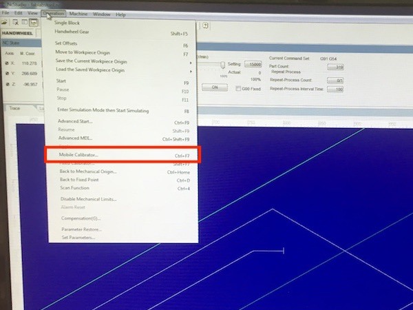
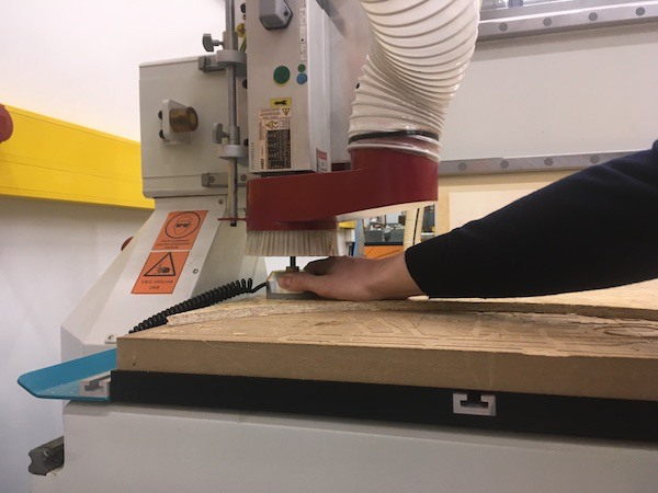
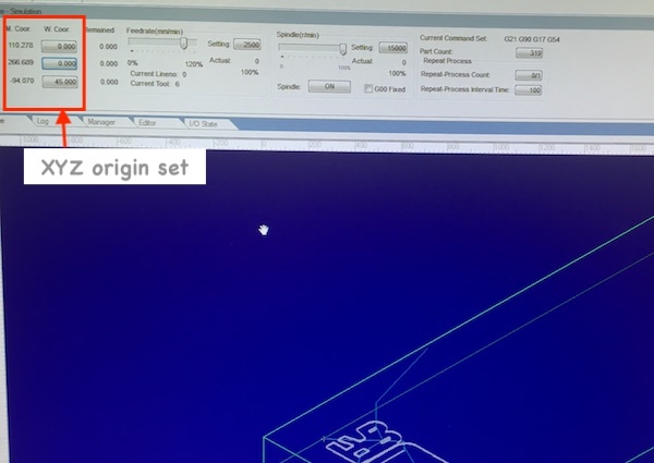
I followed the process as above to set up the machine. I removed all the movement recorded on the screen (right click> clear). Then I opened the file (File> Open and load). G-code was shown on the screen. I clicked simulation to see how it moves. I turned on vacuum pump buttons for table and dust collection pump. I set Feedrate (mm/min) 80% and spindle (r/min) 70%. If we operate in a wrong way, vibration will cause damages to the CNC machine. So we should be careful not to operate the machine with too much spindle and Feedrate. If these values are too much, the milling sounds gets higher. We should pay attention to the high pitch sounds and avoid operating the machine with too much force. I started milling by clicking start button. 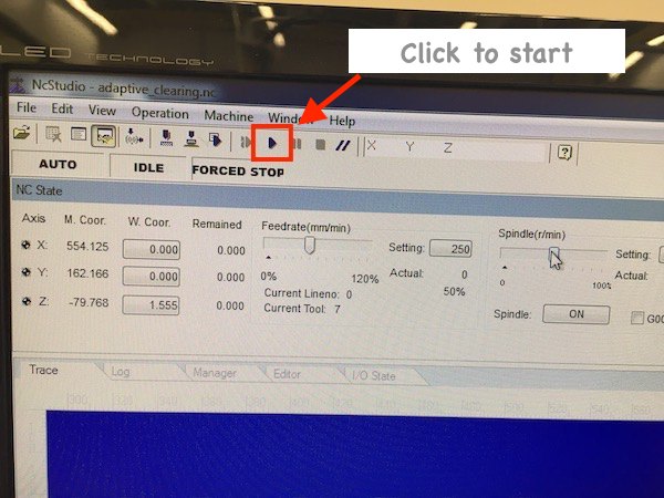
While it was being operated, I could see which process the machine is operating now by the colour change of g-code on the screen.
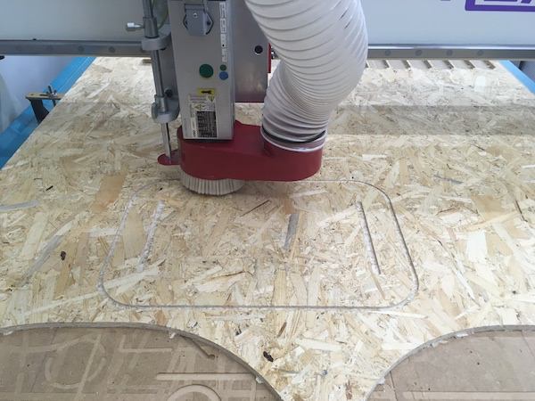
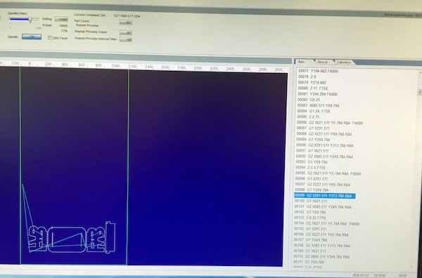
After the parts were cut, I used cutter to remove parts. Since each pieces was attached to the board with tabs, it required a little bit of force.
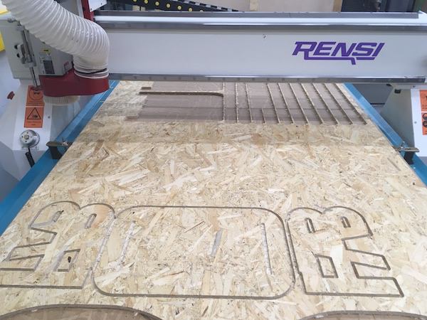
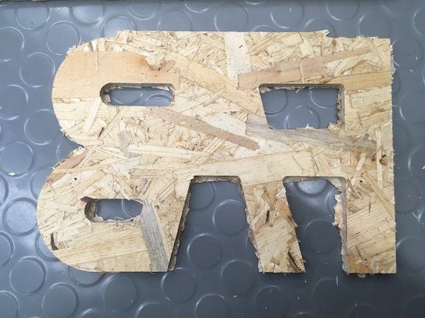
After I removed parts, I sanded and made the surface and the edges smooth.
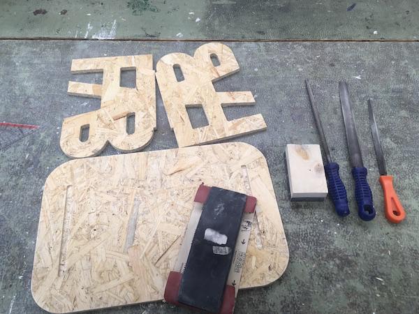
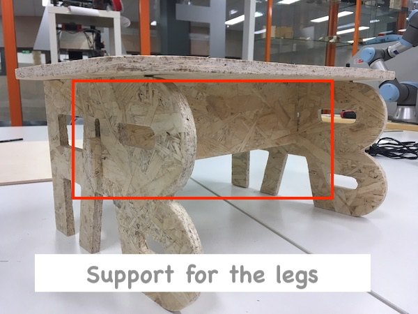
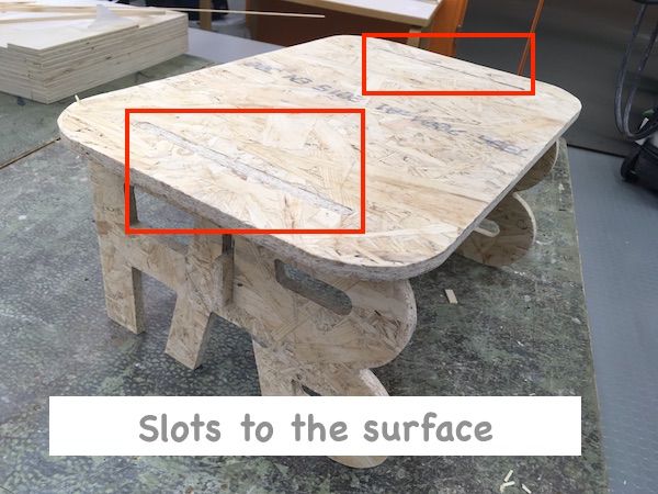
After I sanded, I tried to assemble. But I realised that the legs were not strength enough to hold. I only made the pocket with the half depth of the material. I need to make the pocket deeper to the surface of the top and use support like bridge between legs to keep the legs stand and stable, like this stool.
Also I forgot to add dogbone on the corners of joint tabs. So I needed to remove some material to fit them to the slots. Next time I will also apply dogbone to the corners of joint tabs as well.
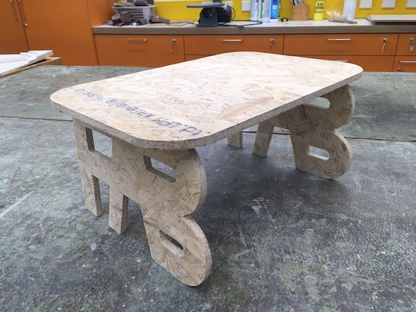
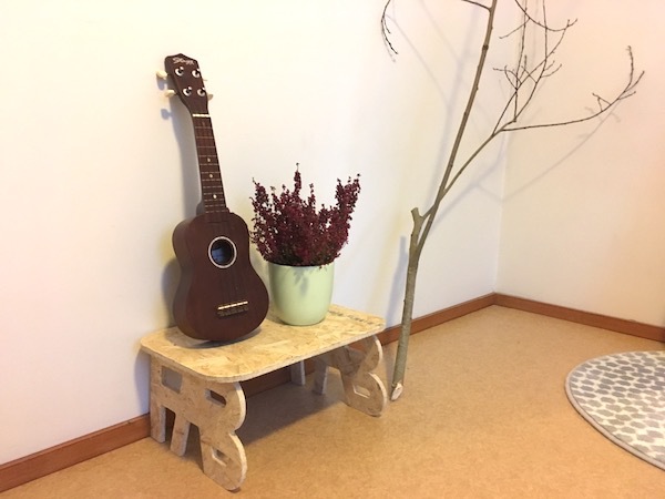
I fixed the design and made another one. This time I made support between two legs to keep them stand. And I made halls on the surface, not the pockets, the legs can be stable enough.
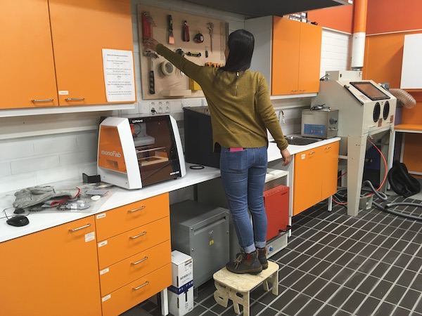
This week, I used the CNC machine fir the first time. I found advantages and limitations of the CNC machine. One advantage is, compare to laser cutter, it is possible to cut thicker wood material, and cutting surface of wood doesn’t burn and looks very beautiful. Also making pockets with different depth is a big advantage. As the limitations, the machine cannot make 90 degrees corners, so we need to design so that the machine can perform properly. Also operation of the machine and finishing process after cutting require some effort. But it was good learning to understand characteristics of CNC machine. I found it is useful machine and very fun to design and make big objects.
Here are the files 3D model of the stool (f3d/ step/ NC).
For one of the ideas of my final project, I wanted to make planets. So I wanted to try to cut a sphere with CNC machine. I used 45mm thick wood piece and 8mm ball head bit. 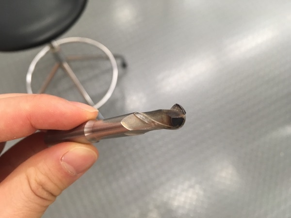
I created a sphere and cut into half in Fusion 360. 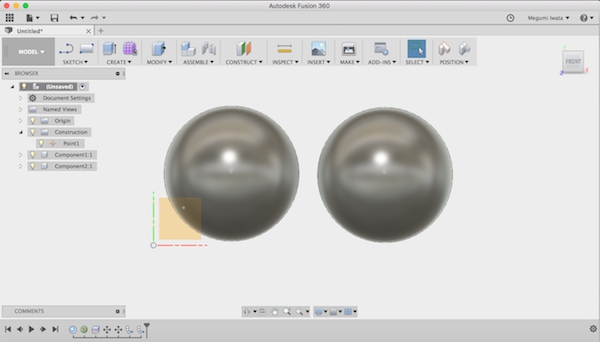
I changed to CAM mode. I made new setting. I used Adaptive clearing (3D> Adaptive clearing) and 2D contour (2D> 2D contour). Adaptive clearing includes roughing which cuts large quantity of 3D model roughly and refining which cuts more precisely according to the design. With this way, it is possible to make 3D objects effectively. 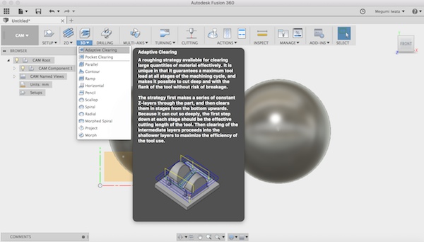
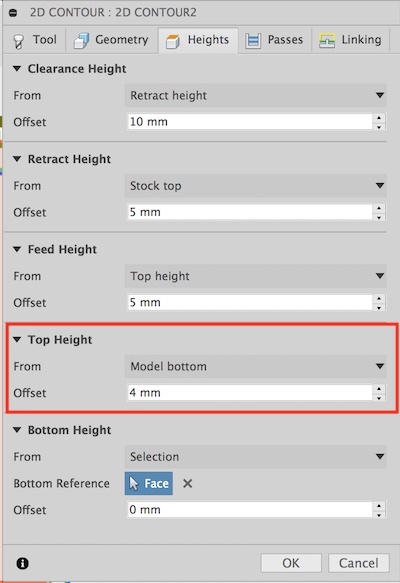
In Adaptive clearing height section, I set bottom height 3mm up from model bottom, and in 2D contour setting, I set top height 4mm from model bottom. Since milling starts first, so I don’t need to cut from the model top where material is already cut out. The machine mill the half sphere till 3mm to the bottom, and starts cutting around the bottom.
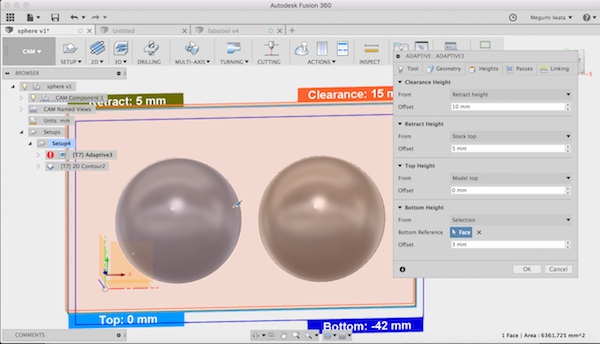
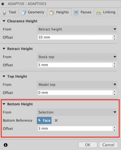
After set everything, it calculated and created tool paths according to the depths of the design. 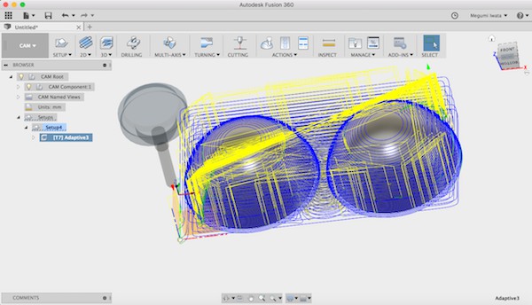
I set 8mm ball bit on the machine, set origin and started cutting.
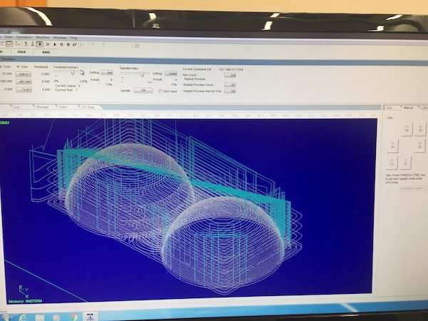
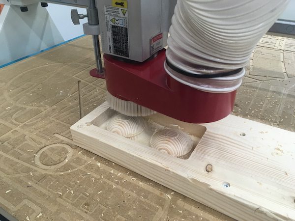
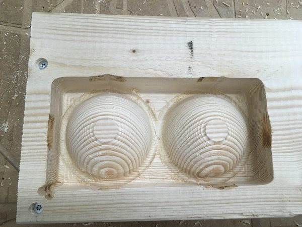
After cutting, I made halls in the middle of the circles, put a wooden tab and glued them together.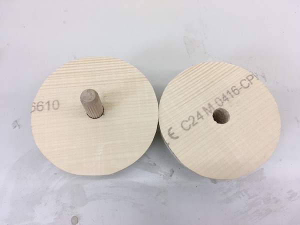
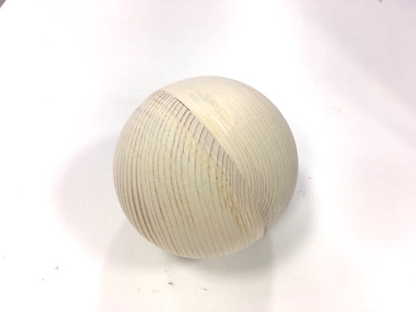
After I cut, I realised that there are dents in four side of the half sphere. 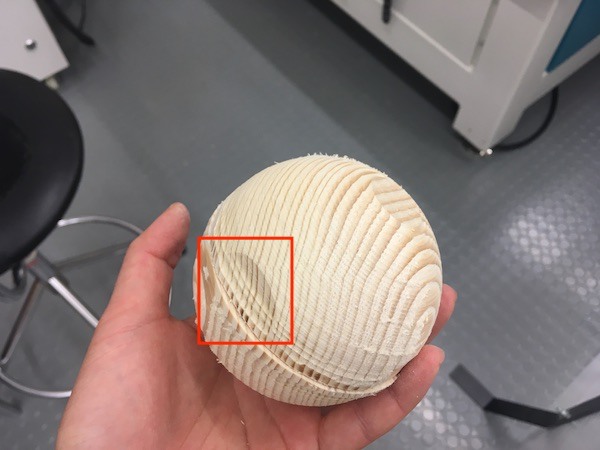
Extra material was cut out when it cut the side close to the edge. I should have set stock size bigger enough so that there is enough space for the bit to go. 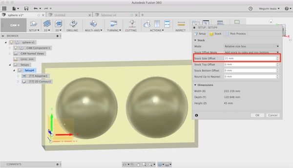
Another thing is I could change lead & transition and ramp type. It would make process a little bit quicker. It took around 40 min to cut 90 dimeter sphere.
Also I realised that I forgot to change the cutting depth. The one time cutting was very deep. After cutting I checked settings, it was set 10mm. I should have changed to something like 5mm.
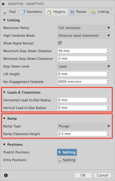
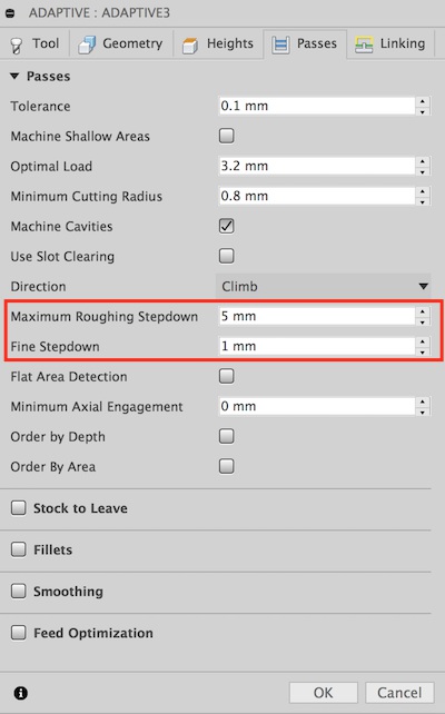
Later Fab Lab Oulu director Jani gave me feedback that I should have ckecked collisions in simulation in Fusion 360. It is a good way to find problems in design regarding milling process. When you simulate milling in Fusion 360 CAM mode, the paths which may have problems, such as too narrow space, are shown as red in the bottom of the window. Here is the video explains collisions in Fusion 360.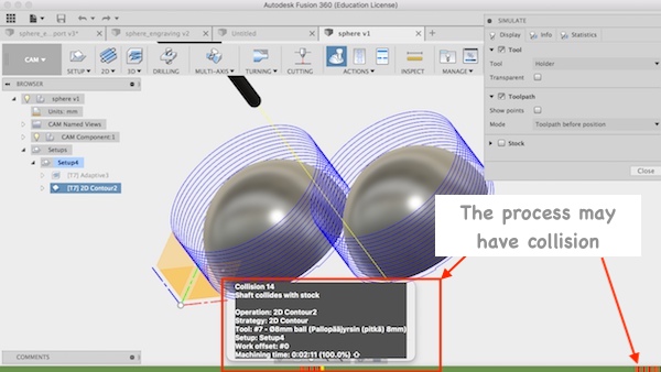
Here are the files of 3D model of sphere (f3d/ step/ NC).