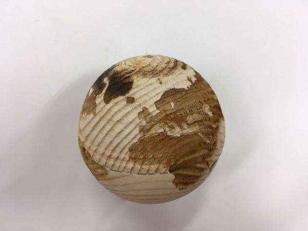
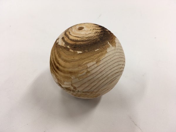
Laser engraving on the sphere
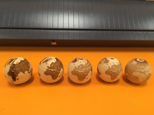
I decided to try laser engraving on the sphere using rotary attachment which rotate a target object 360 degrees. It is used to cut and engrave cylindrical objects with laser cutter. My plan was to use this rotary attachment to engrave world map on the sphere which will be used in my final project. I found the instructions which explains how to laser engrave on the sphere. I followed the instructions to engrave on the small sphere. Later I tried with the bigger sphere. Eino helped me and gave me advices during the process.
Preparation
To set the rotary attachment on the laser cutter, I turned off the switch of laser cutter, removed the stage where usually the material is placed. I placed the rotary attachment in the left corner of the laser cutter and plugged the cables. The object should be placed on two wheels on each side of the rotary attachment.
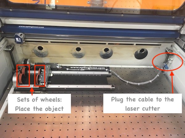
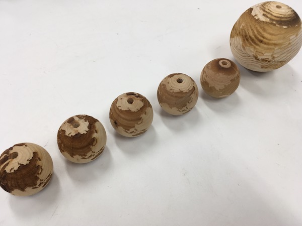
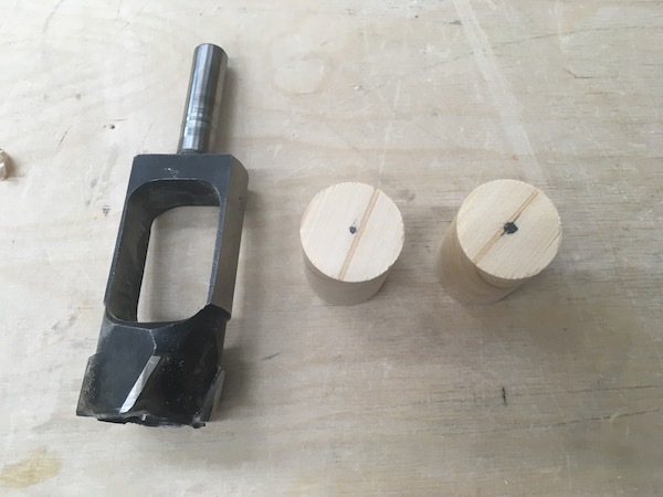
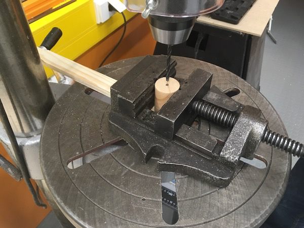
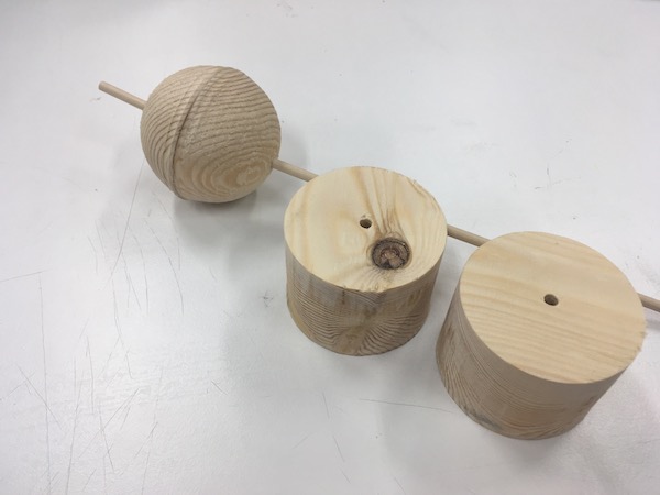
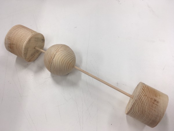
I bought 35mm diameter (it was actually 34mm when I measured) sphere beads to test engraving on the small sphere. The rotary attachment rotates the sphere bead for 360 degrees and the image is engraved on the surface. To set the sphere on the rotary attachment, I used a stick which diameter is almost as same as the hole diameter of the bead. I strung the stick through the bead. I added small amount of Blu Tack to fix the position of the sphere. The stick was thinner than space between two wheels so I needed to have support pieces to keep the stick between the sets of two wheels. I cut two cylinder shaped pieces from the thick wooden piece. I made a hole which is the same diameter as the stick.
I sticked the wooden piece on each end of the stick. I placed the stick with sphere on the rotary attachment. I adjusted the height of the right wheels so that the stick is set as horizontal.
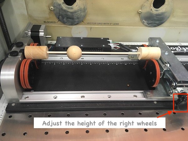
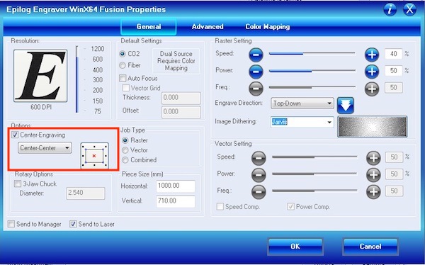
As normal laser engraving, I needed to set x-y origin and focus (height of the stage, distance with laser and the material surface). Operation details are documented in week 4. I used center engraving which is the option of the laser cutter setting which the center of the image is adjusted to the origin point (set origin in the center of the object). Thus I needed to find the center of the sphere to set it as origin. When the rotary attachment is used, the y axis is automatically decided. First I set the origin when the pointer was on the left edge of the bead. I moved the pointer to the right for half of the diameter (34mm /2 = 17mm). Setting the focus is problematic. The focus can be set on only one height, so if the focus is set on the top of the sphere, the image will not be engraved enough on the edge of the sphere, while if the focus is set on the edge of the sphere, the image will be engraved too much on the top of the sphere. In the instructions, the person was set the focus in the middle of the highest point (top of the sphere) and the lowest point (edge of the sphere) so that the gap between highest and lowest points is going to be halved.
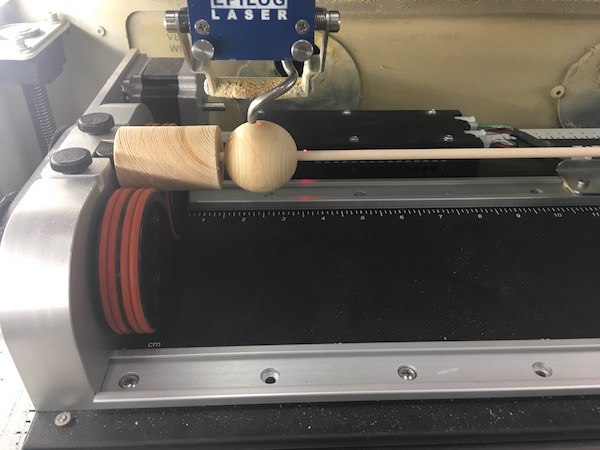
Set the origin on the center of the sphere
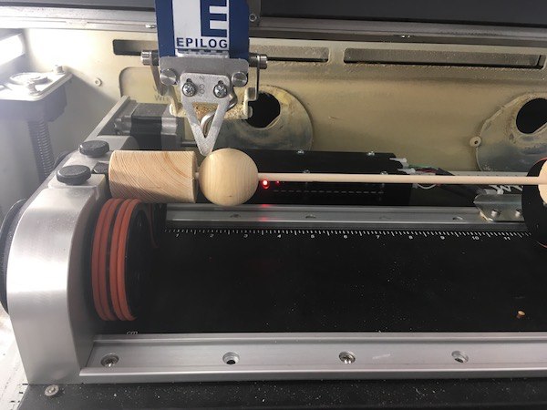
Set the focus in the middle of the height
Experiment
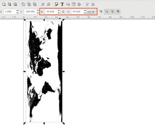
I searched world map from internet. I downloaded the map and imported in Inkscape. The world map should be rotated 90 degrees so that the map is engraved on the rotating sphere. The width of the image is diameter of the sphere, the height of the image is circumference of the sphere. I had problems mainly about the strength of the engraving, X direction (the map width in the 90 degrees rotated image, direction of North-South) and Y direction (the map height in the 90 degrees rotated image, direction of West-East). Each time I changed settings based on the the pevious results.
First trial
As the first experiment, I did not have much clue of settings, I used following setting to see how it works.
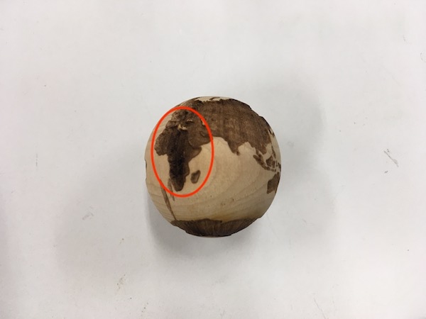
Result
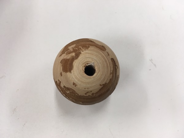
Problem in strength of engraving: The parts near the top height of the sphere was engraved too much.
Problem of Y direction: The image was not engraved 360 degrees on the sphere. There was about 7mm space between one edge and another edge of the map. I thought it was because the height of the image was too short (which I found later it was the wrong assumption).
Second trial
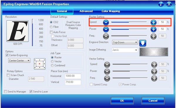
Based on the result of the first trial, I increased the speed and changed the height of the image 7mm longer.
Result
Problem in strength of engraving: Engraving on the top of the sphere was still a little bit too much.
Problem of Y direction: This time the edges of the map were overlapped.
Problem of X direction: I also realised that there was too much white space left around the South Pole compare to the North Pole. So the map was engraved too close to the North Pole. Eino pointed out the reason why the map was engraved too close to the North Pole side was that in the image I used, the North Pole was not shown as the engraving area which should have been shown as black. With center engraving setting, when the laser cutter calculated center of the image, the North Pole was not included in the engraving area. Thus the map was engraved too close to the North Pole.
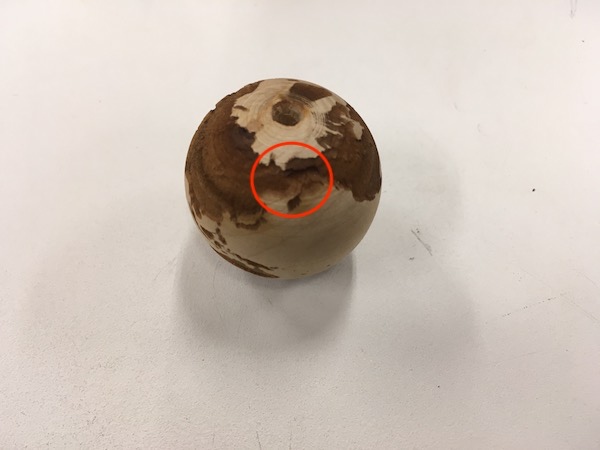
Overlapped
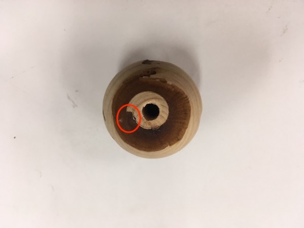
Overlapped
Third trial
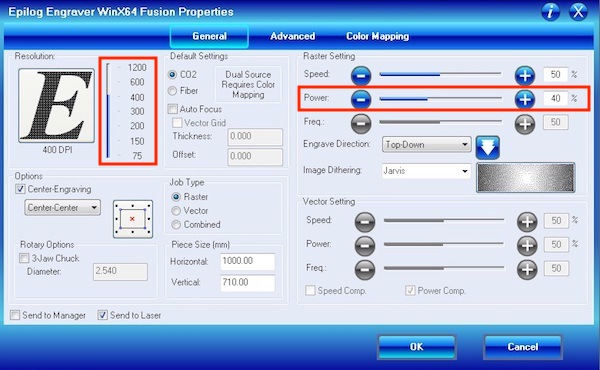
Based on the result of the second trial, I reduced the power and resolution. I also shortened the height of the map. To fit the center point on the sphere and the image, I measured the width of the engraving area (32mm). I set the initial origin on the right edge (South Pole side) of the sphere and moved half of the width of the engraving area (32mm /2 = 16) to the left to set the actual origin. With this way, the origin is not in the center of the sphere, but closer to the South Pole which is the center of the engraving area in the image.
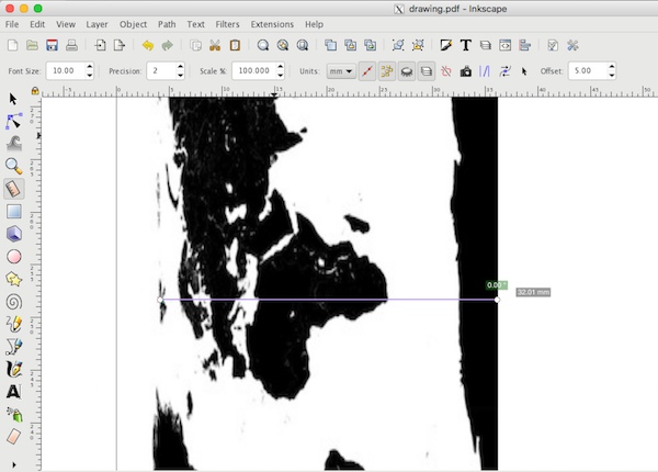
Measuring the engraving area
Result
Problem in strength of engraving: The strength of engraving was okay this time.
Problem of X direction: The balance of the North and the South was good this time.
Problem of Y direction: The edges of the map was still overlapped. It was because circumference of the sphere and the support wooden pieces were different. Circumference of the wooden pieces was 30mm, while circumference the sphere was 34mm. The laser cutter recognises the object on the set of two wheels which is support wooden piece, not sphere. So I needed to set the image width as circumference of the wooden piece.
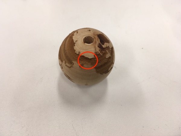
Overlapped
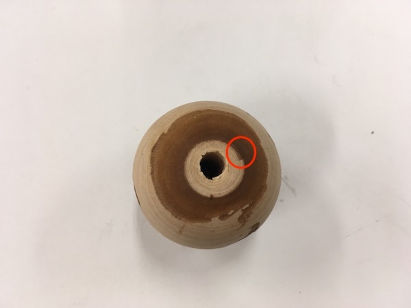
Overlapped
Fourth trial
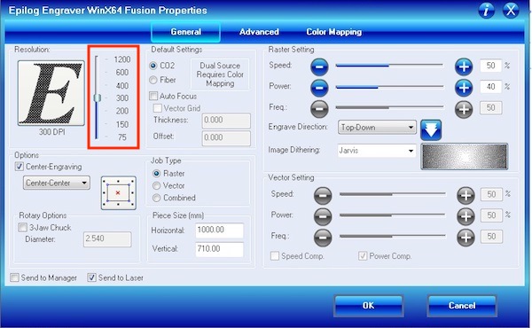
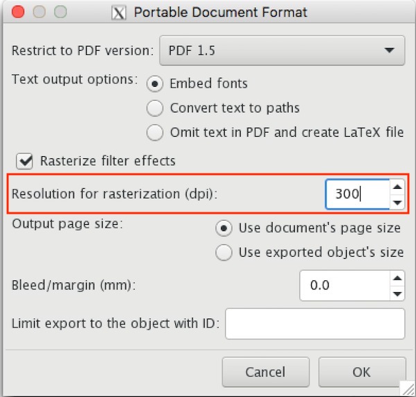
The circumferece of the wooden piece which diameter is 30mm is 94.2mm. I changed the height of the image as 94.2mm. I also reduced the resolution too 300 dpi as same as I set when I export the map from Inkscape to PDF. To set the origin, I took the same way as I did in the third trial.
Result
Finally I got a good result.
Fifth trial
I changed engraving area from the continents to the ocean. I tried inverted the map in Inkscape but when I exported as PDF, it somehow went back to the original image. So I used GIMP to invert the image.
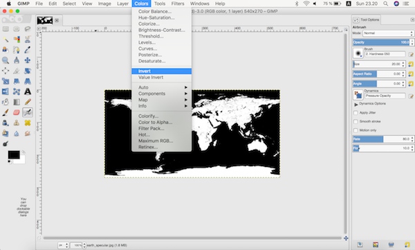
Result
The result was almost perfect. There was a small gap left between the edge of the map. Since the ocean on the both edges of the map were engraved, the gap was more noticable than when the continets were engraved.
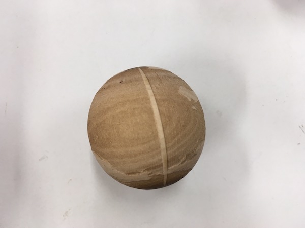
Engraving on the bigger sphere
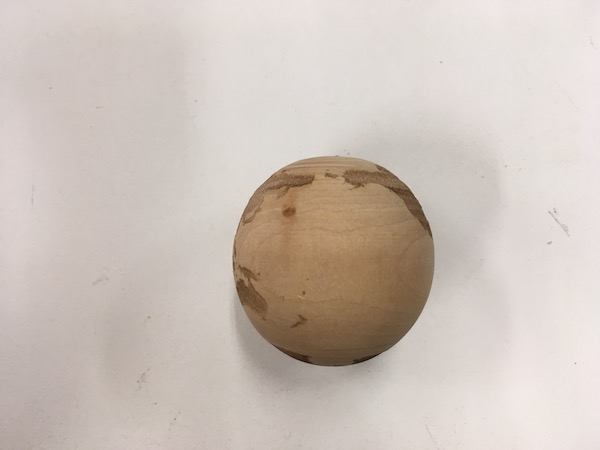
I tried engraving on the bigger sphere. This engraved sphere will be used as the earth for my final project. For the bigger sphere, probably one focus is not enough because the gap between the highest point and the lowest point is big. So I made two files, file 1 has whole image and file 2 has only right and left sides of the image are visible. My plan was setting the focus on the highest point of the sphere and engraving file 1 first. The image will be barely visible on the lower part on the both sides (the North Pole and the South Pole) because the laser is too far from the surface. Then I will set the focus on the lowest point and engrave file 2. This time, the image will be engraved properly on the lower part and nothing will be engraved on the higher part.
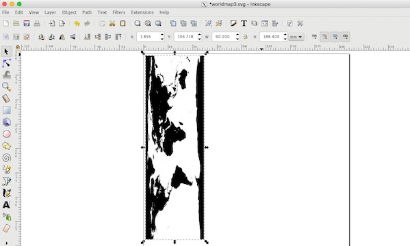
Focus on the highest point
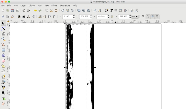
Focus on the lowest point
Preparation
Making the sphere
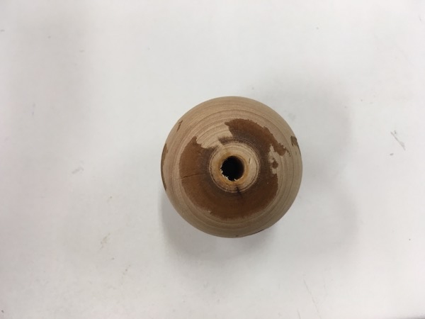
I made the sphere and the support pieces with CNC machine. As I did in week 8, I made two half spheres of 60mm diameter and attached together to make the sphere. This time I also made two cylinders of the same diameter as the support pieces.
First, I designed the half spheres and cylinders in Fusion 360. I drew a sphere of 60mm diameter and cut it into half. I alligned them on the same plane. On the same plane, I drew two cylinders of 60mm diameter. I kept 12mm gap between each body so that 8mm ball head milling bit can go through between the bodies.
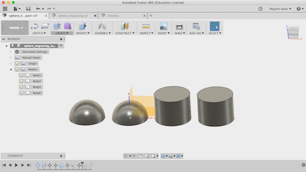
I needed to have holes to put through the stick in the middle on each body. I selected the bottom of one body and created sketch. I drew 4.5mm diameter circle which is the diameter of the stick in the middle of each body.
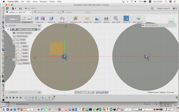
I stopped sketch and extruded the circles as cut to make holes.
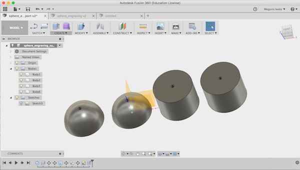
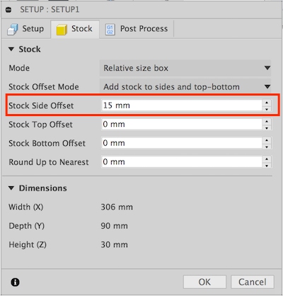
I changed to CAM mode to create tool path for milling. Detailed documentation of the settings can be found in week 8. I created new set up. I changed stock side offset as 15mm so that there will be enough space for the 8mm milling bit to go through.
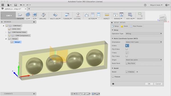
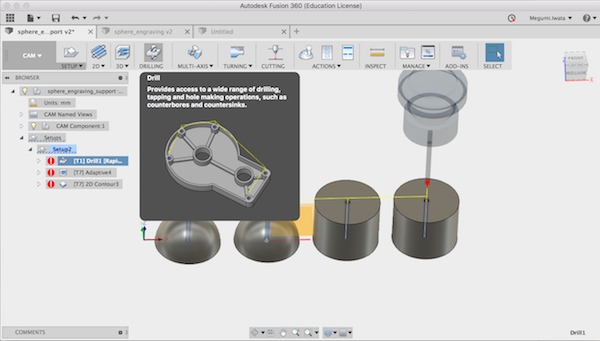
I chose Drilling.
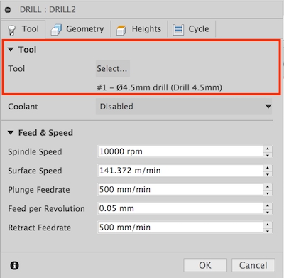
Here I used 4.5mm diameter drilling bit.
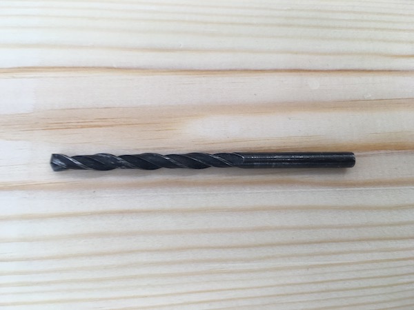
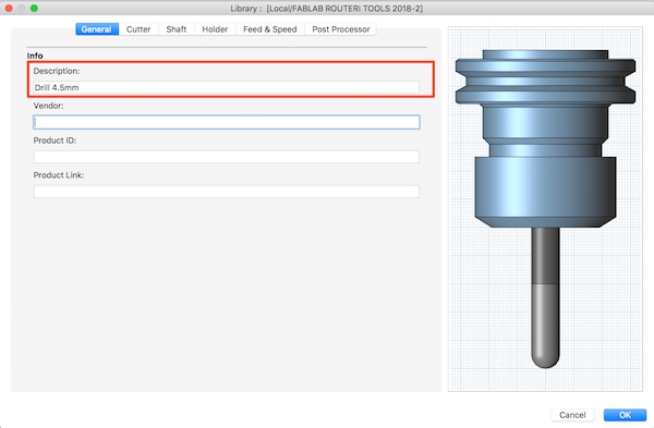
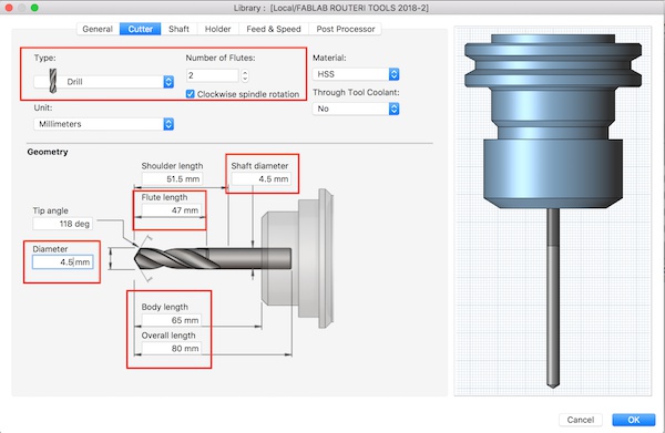
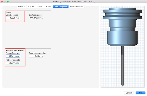
The drilling bit was not in the library, so I created a new tool.
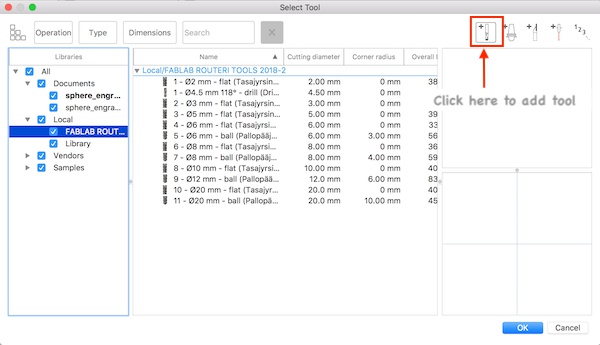
I selected Drill, 2 flutes and measured the diameter and length of each part of the drilling bit and added information in the geometry section.
I selected the tool I added.
In geometry section, I chose four holes.
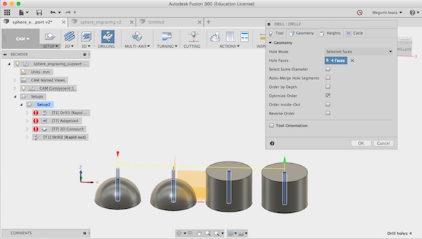
In height section, I chose Top Height as Stock Top and Bottom Height as Stock Bottom.
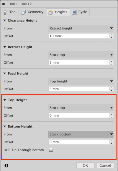
I clicked OK and tool path for drilling was created.
Next I made tool path for adaptive clearing (3D> Adaptive Clearing). In this process, I set as same as I did in week 8. I selected 8mm diameter ball head milling bit. In Height section, I selected one of the bottom faces and set offset 3mm as bottom height. With this way the bottom part is still attached on the whole wooden piece and will not move when it is cut later. In Passes section, I changed maximum roughing stepdown 5mm, fine stepdown 0.5mm. I removed stock to leave. In Linking section, I changed Leads and Transitions as 0. I changed Ramp type Plunge. I clicked OK and tool path for Adaptive Clearing was made.
Next I made tool path for cutting. I chose 2D Contour (2D> 2D Contour). I used the same milling bit, 8mm ball head. In Geometry section, I chose the bottom edges of four bodies. In Height section, I selected Model bottom and set offset 4mm as Top Height. Since I left material 3mm from the bottom when I created tool path for Adaptive Clearing, with this setting for Top Height, the bodies will be cut. I selected one of the bottom faces as Bottom Height. In Passes section, I removed Stock to Leave. In Linking section, I removed Leads and Transitions. I clicked OK and tool path for cutting was made. I simulated the tool paths and downloaded G code with two different files, Drilling and Adaptive Clearing and Contour (Right click> Post Process).

While I was setting up the machine, I found that drilling bit could not fit in the CNC machine. (*Later I got to know that I can attach the drilling bit on CNC machine. So the file I made for drilling can be used) I changed the plan and made two different tool path for holes for the sphere and the cylinder as 2D Pocket. I used 3mm diameter milling bit for this process. The height of the holes on the sphere and the cylinders were different so I needed to make different files for each of them. The flute length of the milling bit was about 20mm so I decided to make 10mm depth holes and later drill them through.
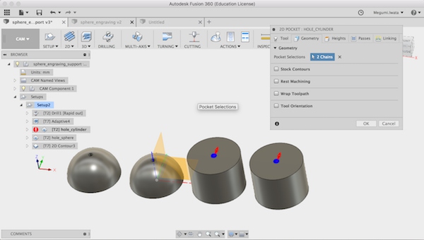
Select holes to mill
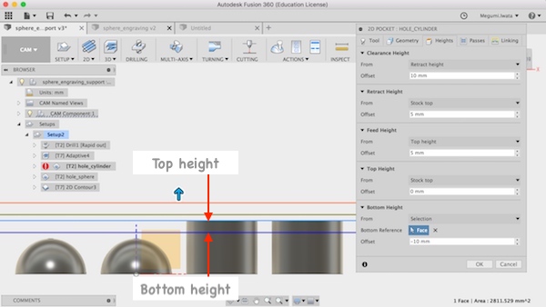
Select top and bottom height
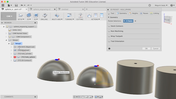
Select holes to mill
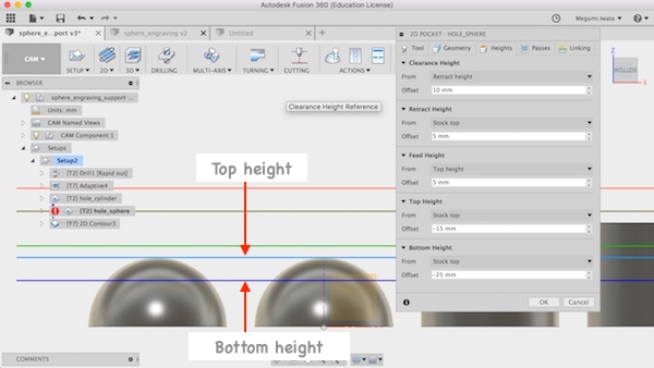
Select top and bottom height
I downloaded G code as four separate files for Adaptive Clearing, Holes for cylinder, Holes for sphere, and Contour (Right click> Post Process).
*Later I found that I should have made files for holes for the sphere so that it would make holes from the stock top. With that file, I do not need to change milling bit twice in the the process and would be more efficient.
I set up the CNC machine as I did in week 8. I set the xyz origin and opened and loaded the file for Adaptive Clearing first. I simulated on the screen and started milling. Right after started milling, the milling bit went out of the stock. So I stopped the process. I got the bigger wooden stock and started milling again. I should have simulated the process in the air and checked the stock is big enough. I started milling. I started spindle speed 70% and feedrate 40%. I increased the feedrate to 65%.
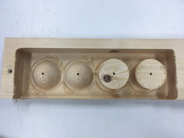
After I finished milling, I used drill to make a hole through each piece. I strung the stick through the holes and attached half spheres together with glue. I sanded the pieces.
Engraving on the bigger sphere
I set the sphere on the rotary attachment.
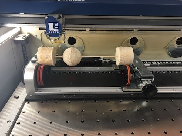
I set the origin point first on the edge of the sphere and moved to the middle for half of the diameter (60mm/2 = 30mm).
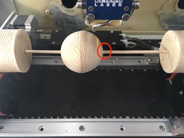
Set initial origin on the edge
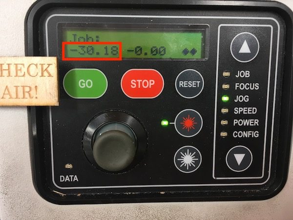
Move for half of the diameter
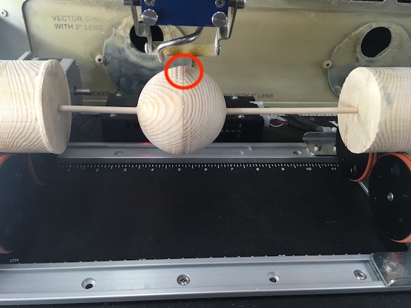
Set origin again
Next I set the focus. My plan was focus on the top (highest point) first and engrave, then change the focus on the edge (lowest point) and engrave. So I adjusted focus on the top. When I selected focus on the operation monitor on the laser cutter, it moved to the middle of two sets of the wheels. I attached the sphere on the left from the middle so it was difficult to adjust focus. I should have set the sphere in the middle.
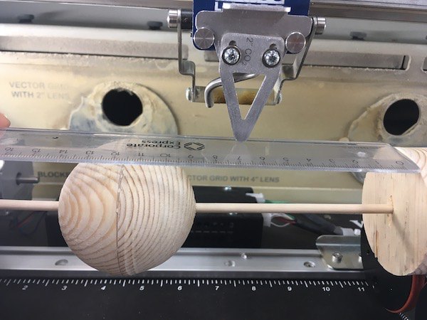
I used the same setting with the fourth try as I described above.
It turned out that the image was engraved stronger on the sides of the sphere. I could not find the exact reason. One possibility is the surface of the sphere was not smooth and the parts might be easier to be burned. Another possibility is the angle was steep and laser was exposed more frequently on the parts near edges.
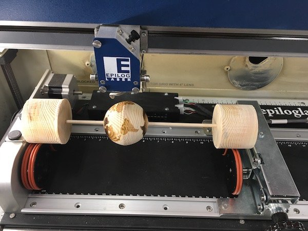
But otherwise result was good!
Conclusion
When you engrave the image on a sphere:
- Use rotary attachment. String the stick on the sphere and add support pieces on both sides of the sphere.
- Set the origin on the center of the sphere and use center engraving.
- The image should be:
Width = diameter of the support piece
Height = circumference of the sphere
- If the diameter is small enough, it is possible to engrave with focus which is adjusted in the middle of the highest and lowest points of the sphere.
