Final project proposal
Initial idea: Cube lamp
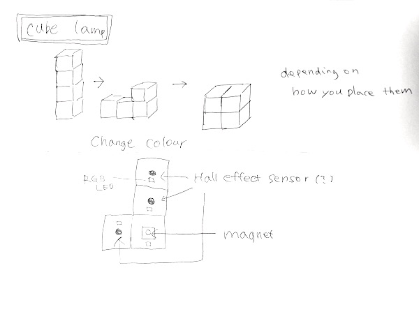
I would like to make cube shaped lamps which change the colour depending on how they are placed.
The design idea came from LEGO. Even though we can make or buy many nice looking things, but we still love LEGO. It is because it does not have fixed shape but it can be anything. I wanted to have that kind of thing, simple pieces but can be any shape with imagination. As I love LEGO, I will love this lamp for long time.
The performance idea came from other people’s projects. During Fab Academy, I saw many good projects of other people, such as this and this, and got interested in how people can interact with technology in daily life. It would be nice if I can change colours depending on how I place it.
I am thinking to use hall effect sensor as its sensor. I am going to put magnet in one of the cubes and sensor in other cubes. With this sensor it is possible to measure how far those cubes are placed. I am going to change the values of RGB LED in each cubes depending on the values of the sensor.
About the material, I am thinking to use Washi (Japanese traditional paper), for the surface and wood for the structure.
I found similar products, Tetris Stackable LED Desk Lamp and LED Light Rechargeable Desk Lamp.
It might be better to put frame of metal to supply power to each cube and put sensor on it.
Learning and testing possible sensors
For my project, I need to sense the distance between cubes to change colour or brightness of the LEDs in each cube. I looked for information of possible sensors for the project in Input week in Fab Academy 2018.
Here are the options that could be used for my project.
- Distance sensor
- Magnetic field sensor: Hall effect
- Light sensor: IR
- Step response: loading , Transmit-Receive
Learning about hall effect sensor
I started get familiar with the most probable sensor, hall effect sensor in this website. Hall effect sensor provide a voltage when the sensor is placed in the magnetic field. It changes the voltage depending on how close it is to the magnet. There are two types of hall effect sensor. Latching hall effect sensor gives high voltage (5V) when the north pole of a magnet is brought close. When the magnet is removed, it still gives high voltage. It does not go to low voltage until the south pole is brought close to it. Non-latching effect sensor gives high voltage (5V) when the north pole of a magnet is brought close. When the magnet is removed, it gives low voltage.
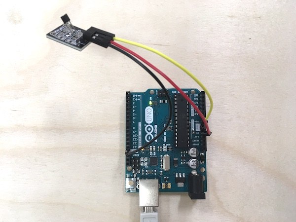
To test the sensor, I used sensor kit for Arduino. I referred to this website to see how I can use the sensor with Arduino. Hall effect sensor has three legs: GND, VCC and signal. I connected Arduino Uno and the sensor.
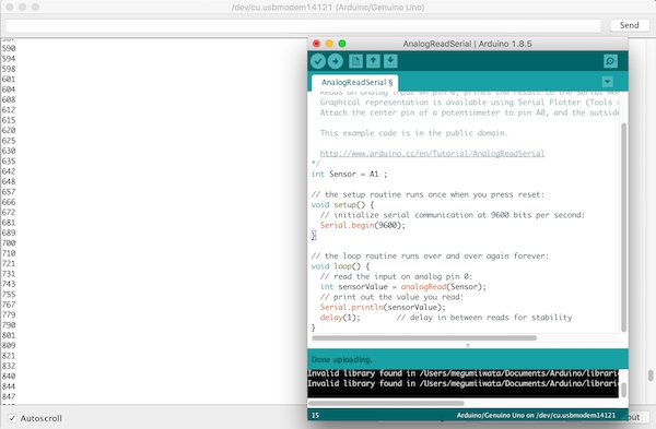
 Code
/*
  AnalogReadSerial

  Reads an analog input on pin 0, prints the result to the Serial Monitor.
  Graphical representation is available using Serial Plotter (Tools > Serial Plotter menu).
  Attach the center pin of a potentiometer to pin A0, and the outside pins to +5V and ground.

  This example code is in the public domain.

  http://www.arduino.cc/en/Tutorial/AnalogReadSerial
*/
int Sensor = A1 ;

// the setup routine runs once when you press reset:
void setup() {
  // initialize serial communication at 9600 bits per second:
  Serial.begin(9600);
}

// the loop routine runs over and over again forever:
void loop() {
  // read the input on analog pin 0:
  int sensorValue = analogRead(Sensor);
  // print out the value you read:
  Serial.println(sensorValue);
  delay(1);        // delay in between reads for stability
}
Serial monitor showed the value changes. Usually the value is around 523 which is about half of the voltage (5V).
When the magnet comes closer, less than 2cm, it increases the value up to 860. When the other side of the magnet comes closer, it decreases the value to 185. So if I set the threshold based on the values it is possible to change colour or brightness depending on how far each cube is placed. The values did not change much if I put paper between the sensor and the magnet. So I can place them inside of the cube behind paper.