Molding and casting a chocolate shark
Designing 3D model for molding and casting
I started designing a shark which is suitable for molding and casting.
The mold is designed and produced as several pieces (I made two pieces: top half and bottom half). The first mold is made from the wax stock, the second mold is made from silicone. In the last molding, two pieces were put together and pour liquid (I used chocolate as material). To pour the liquid in the last molding, we need two holes, one is for liquid and another is for air to go out.
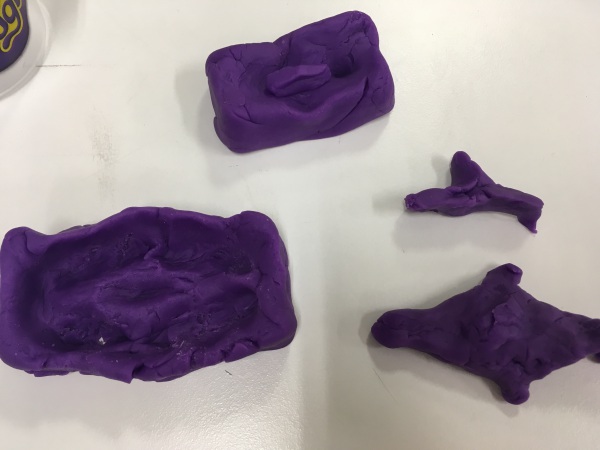
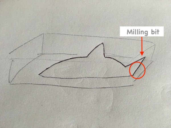
It was very confusing to think three steps include positive and negative of the design. Rough sketching and making each mold and final object with play-dough helped me to understand.
For designing an object for molding and casting there are some things that we need to take into consideration.
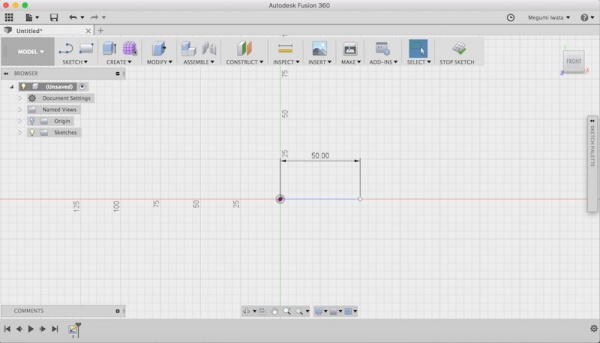
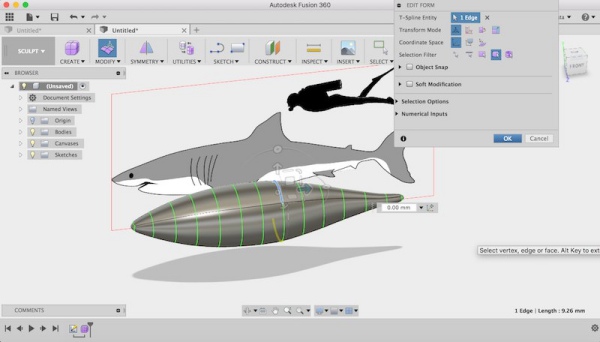
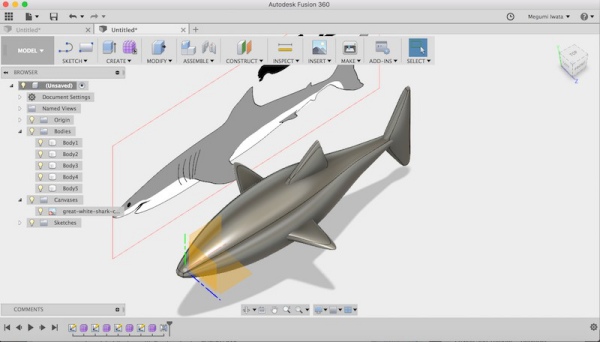
I opened Fusion 360. I drew a line in sketch mode. It is easier to work later if you design this first line from the origin point so that the shark is made on the position which can be split into half from one of the planes (x-y, y-z, z-x plane). I stopped the sketch and I clicked Create > Create form. It changed to Sculpt mode.
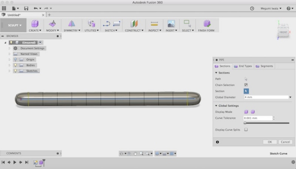
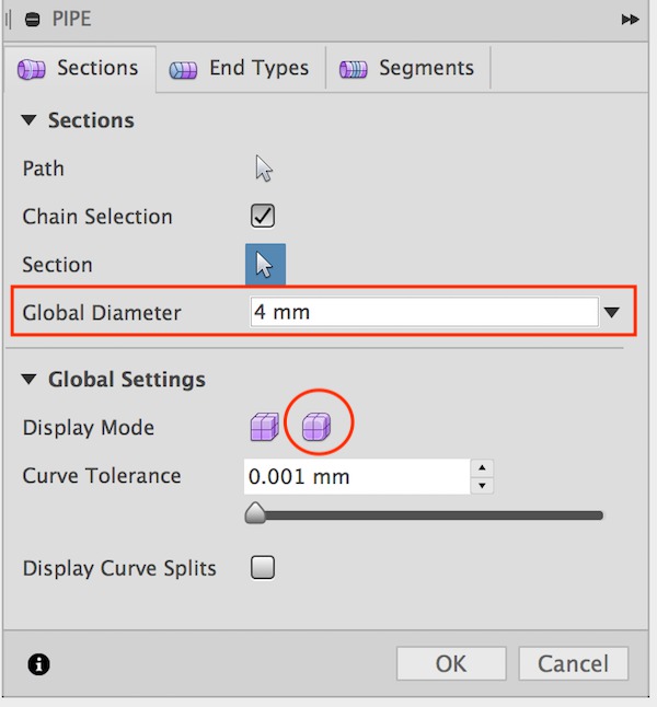
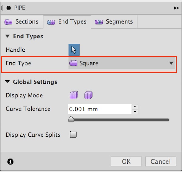
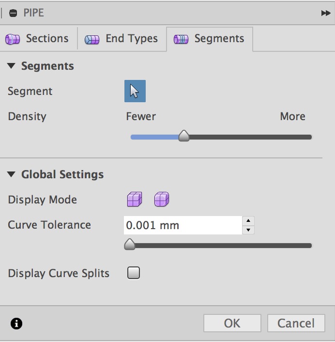
I selected Pipe, set global diameter 4mm, display mode smooth display and end type square.
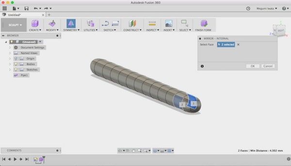
I set symmetry setting for the surface of each side (Symmetry > Mirror - internal).
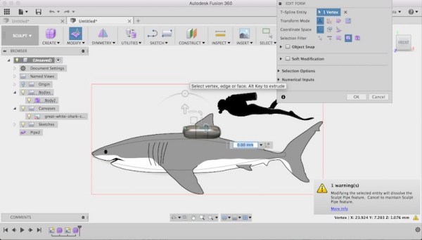
I searched an image of a shark, downloaded and saved it. I inserted the image of the shark as background (insert >background canvas).
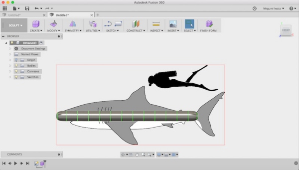
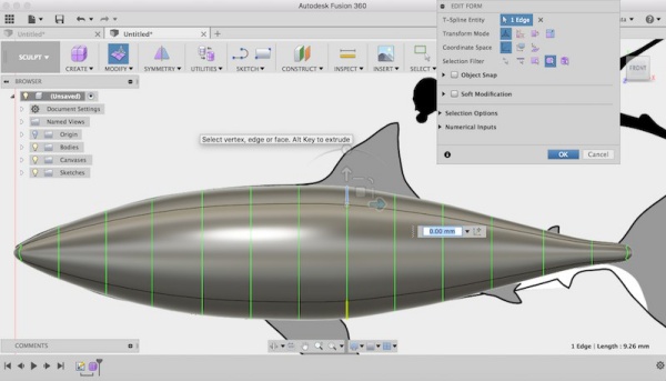
Following the background, I modified the faces and lines of the pipe so that it looks like a shark body.
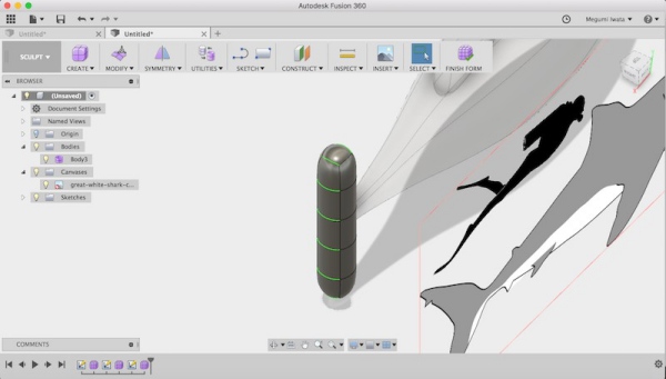
After designing the body, I followed the same method to create fins. Referring to previous students' documentations, such as Jari’s documentation, I payed attention not to make fins too thin so that they can be properly made from chocolate. The thinner part was about 3mm.
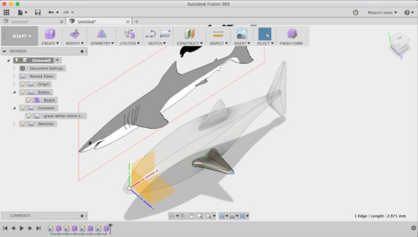
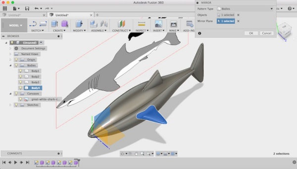
Mirroring the side fin
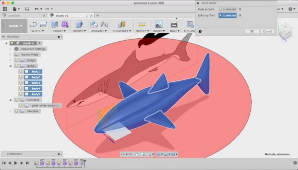
After finished designing the shark, I split the shark into half from the middle (in my case it was z-x plane) (Modify> Split body).
I created a box on z-x plane (Create> Box). Following Jari Pakarinen’s documentation, I made 8mm room between the shark body and the walls of the box. I used shell function (Modify> Shell) to create hollow box. I set direction as outside and specified the wall thickness as 5mm. I copied and mirrored the box on the z-x plane. Now I have the hollow boxes, one is with top half of the shark and another is with the bottom half of the shark inside.
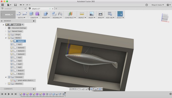
I checked documentations of previous year students who used chocolate molding and casting, and found out no one used the hall to pour chocolate even they used two mold. I thought it would be better to pour chocolate to each mold separately. My plan was pour chocolate into one of them and when it is fixed I pour it into another mold and put them together.
I created registration which helps two mold fit together in the correct place. I drew two 5mm diameter circles on the z-x plane and extruded 3mm on top box as join and on bottom box as cut. I have two cylinders on the top box and two holes of the same size on the bottom box.
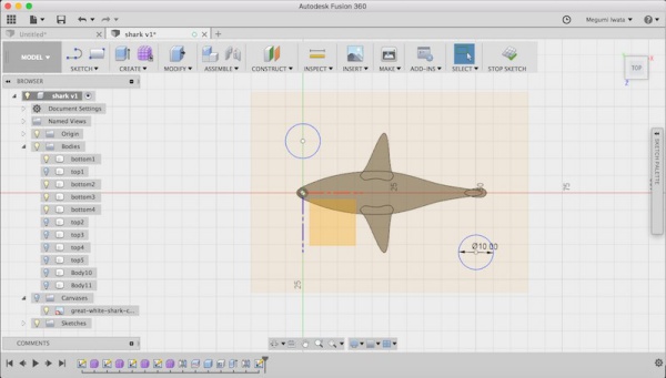
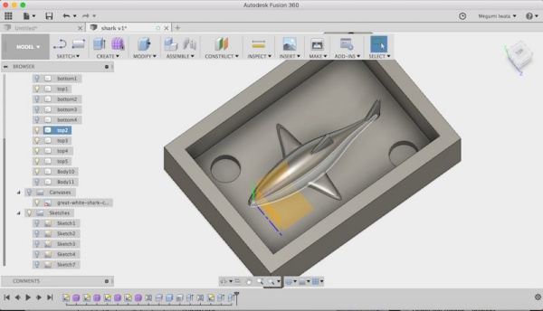
top half
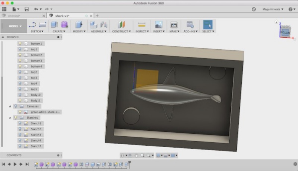
bottom half
I exported each box with the half shark separately as STL. Only the parts of the model which are visible are exported as STL.
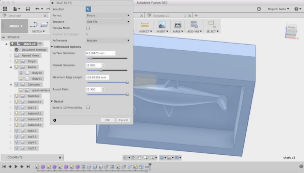
Making the wax mold
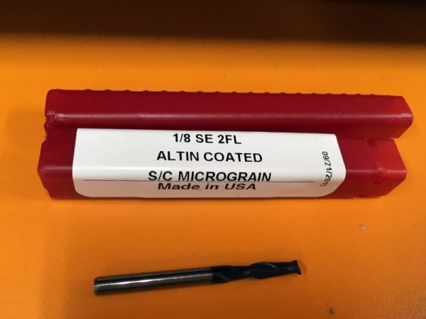
To create the first mold with the machinable wax stock, quicker way is to remove material roughly first (roughing), then making details and smoothing the surface later (finishing). I used 3.18mm flat milling bit to mill the wax stock. There are different milling bits which is suitable for milling details, for example one has 4 flutes or thiner bit, but I didn’t have detailed part that I need to use it so I decided to use 3.18 flat bit for both roughing and finishing.
I used Modela to create tool paths for milling the wax stock for the first mold. I opened the STL file of top half in Modela.
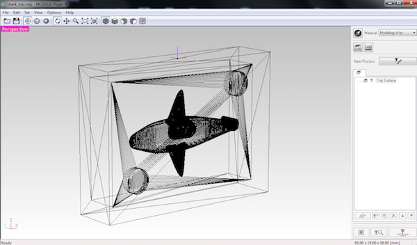
I clicked Set> Model. Here I changed orientation (x, y and z axes) of the model and origin point to the lower left corner where milling machine starts milling.
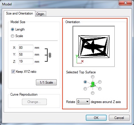
Check x, y, z orientation
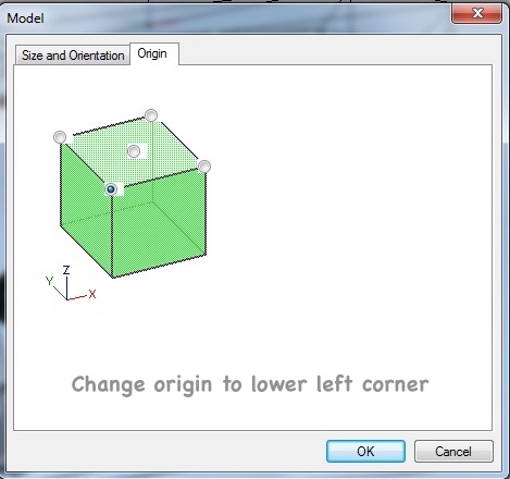
Set origin on the lower left corner
Next I went to Set> Modelling form. I changed to Manual and offset of the model as 0. It is possible to create a box here as well, but I wanted to make sure the box size and to make registration so I designed a box already in Fusion 360. I didn’t change settings of Depth, Slope and Cutting area.
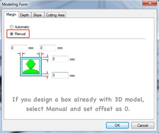
Next I went to Set> New process. Here I created tool paths for milling. I selected roughing. I can add or remove tools from Option> Add/ Remove Tool. I followed Iván Sánchez Milara’s documentation and used the same settings. I used Contour Lines as a tool path type for roughing. With this strategy, the milling bit removes material effectively. For cutting parameters, I set xy speed which is how fast the milling bit moves in x-y direction as 30mm/sec, z speed which is how fast the milling bit moves in z direction as 10mm/sec, Cutting-in amount which is how deep milling bit goes in each path as 1mm, and Path interval which is the distance between a path and the next path (offset) as 1.5mm.
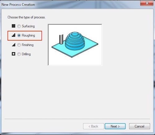
Select process type roughing
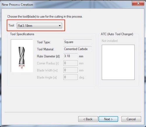
Select correct tool
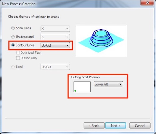
Select Up Cut to remove material roughly
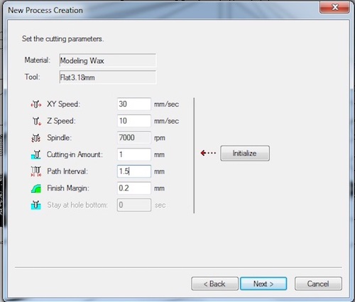
Set the values of cutting parameters
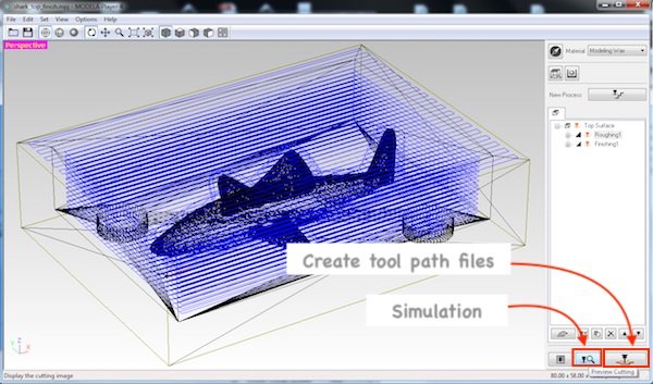
After I set all the settings, I clicked OK and tool paths was created.
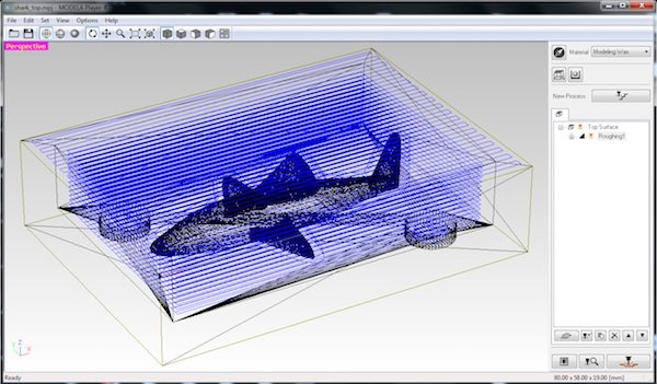
Then I went to Set> New process again. This time I chose finishing. I used Scan Line as a tool path type for finishing and selected x+y direction. With this strategy, the milling bit cleans the surface from both x and y directions. For cutting parameters, I set xy speed as 16mm/sec, z speed as 16mm/sec, and Path interval as 0.2mm. I reduced the values of speed and path interval to smooth the serface.
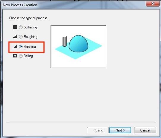
Select process type Finishing
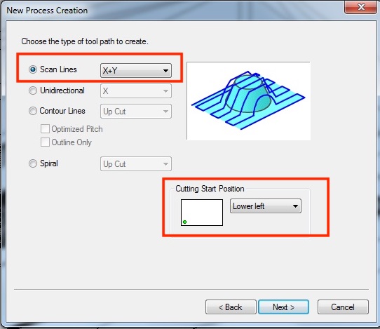
Select Scan Line for finishing and choose the start position
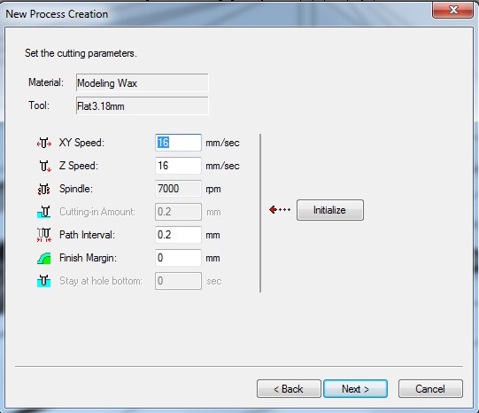
Set the values of cutting parameters
I clicked simulation button and Virtual Modela window opened and simulation was started. I simulated both roughing and finishing. I also checked time. It took 25 minutes for roughing and over 1 hour for finishing. It looked fine so I went back to Modela and clicked Cutting to export the tool paths files. Two files of tool paths of roughing and finishing were created.
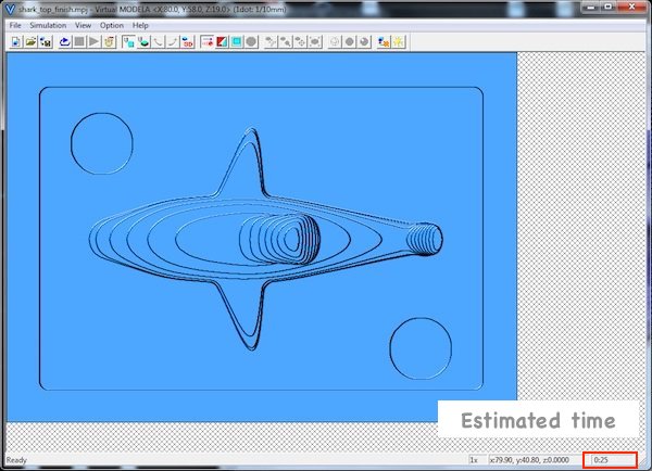
Simulation of roughing
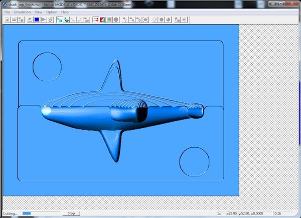
Simulation of finishing
I set the wax stock in milling machine, Roland SRM-20. I applied double sided tape and fixed the stock on the sacrifice surface of the machine.
Next I opened V panel. I followed the same sequence I did in week 5 to set the milling bit and set x, y and z origin.
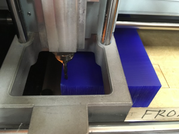
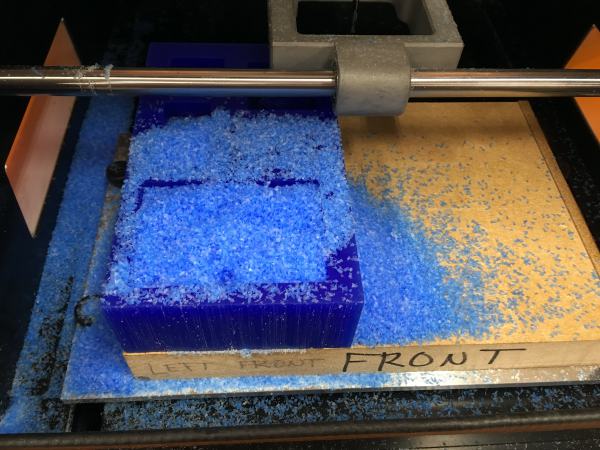
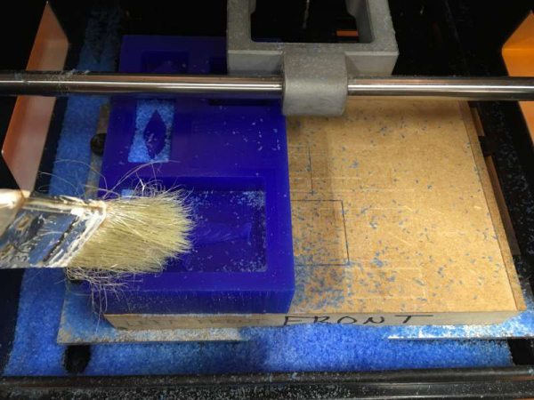
I clicked CUT, deleted previous files and selected the roughing file. I clicked Output and cutting was started. It milled the 3D model roughly. After cutting I collected wax scrap. The was stock can be melted and reused.
Next I selected file of finishing in Vpanel and milled.
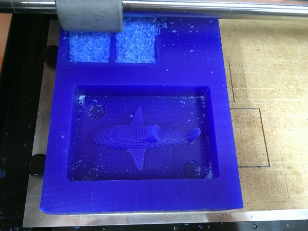
After roughing
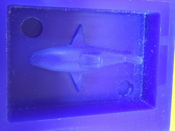
After finishing
Next I made wax mold of bottom part. I followed the same sequence to create tool path.
Problem 1: In simulation, I found one of the cylinders for registration would not be cut properly. I placed the circle to close to the wall and the milling bit can not go through between cylinder and the wall. Since I already milled the top half mold, I couldn’t change the position. So I just deleted the cylinder in Fusion 360 and created the new tool path in Modela again. I should have checked both top and bottom mold before I milled the top wax mold.
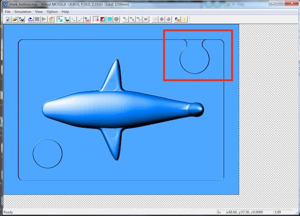
Too close to the wall
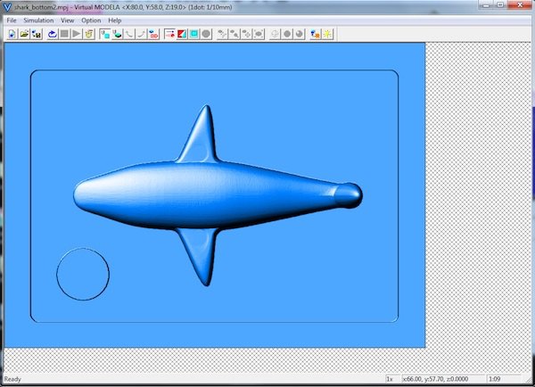
Cylinder deleted
I set x, y and z origin of milling machine in Vpanel and fixed the wax stock on the sacrifice surface.
Problem 2: Soon after cutting started, the wax stock moved and I needed to stop. I could not find an exact reason but most probably I did not set Z origin correctly. Also the wax stock was not fixed on the sacrifice surface. Thus when the milling bit moved, it touched the surface of the wax stock and moved the stock.
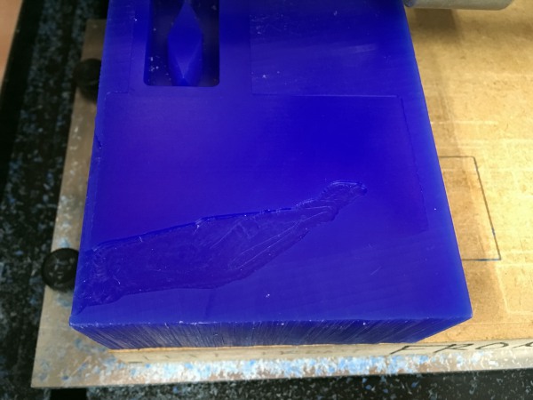
I fixed the milling bit position and milled the bottom half again. This time it worked well.
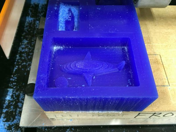
After roughing
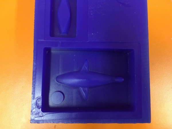
After finishing
Making the silicone mold
Next I created silicone mold. I used Smooth-Sil 940 which is suitable to make a mold for food products. I read data sheet to understand safety and instructions. I turned on ventilation and wore gloves and safety glasses.
Ventilation switch on
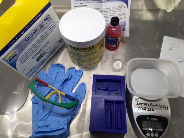
Preparation for silicone casting
Smooth-Sil 940 consists of two parts, part A and part B. Pot time which is time from mixing two parts to casting is 30 minutes and cure time which is from casting to the time that the mold is ready is 24 hours. Following data sheet, I mixed part A and B as 100:10 ratio and stirred thoroughly for 3 minutes.
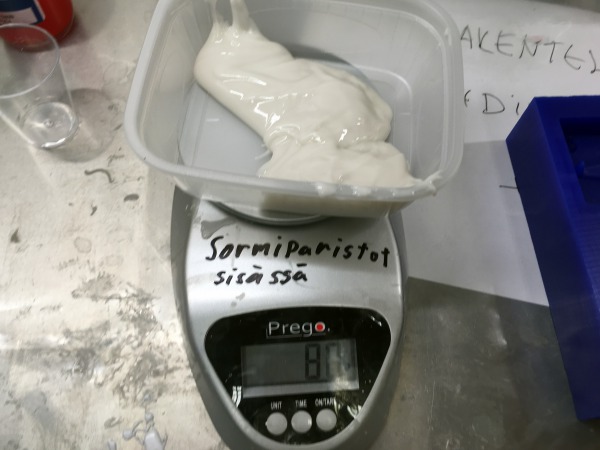
Measuring part A
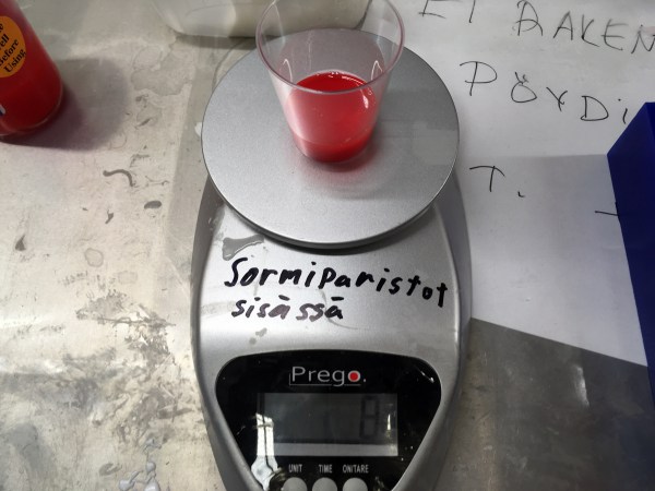
Measuring part B
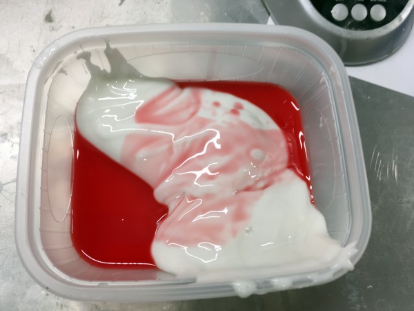
Mixing
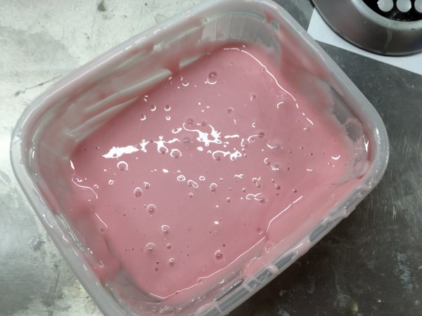
After mixing
Next I put the mixed silicone in the vacuum machine to remove bubbles as much as possible. Bubbles affect the quality of the mold. It is not possible to remove all the bubbles but after 10 minutes, the bubbles were almost removed.
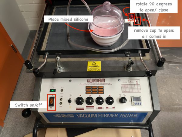
Vacuum machine
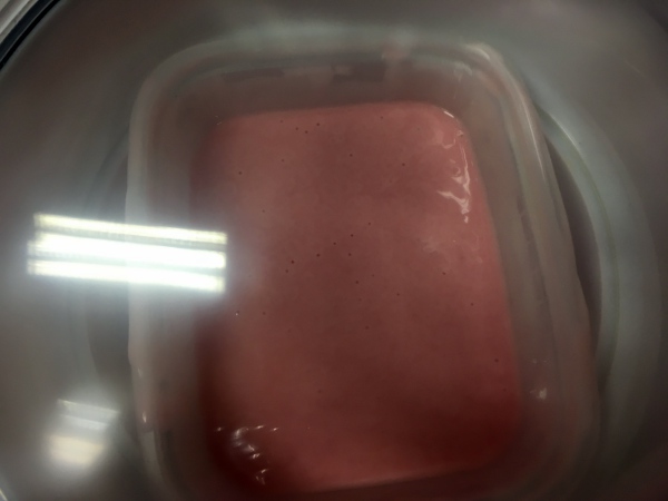
After vacuuming
I slowly pour the silicone on the lowest point of the wax mold and let it flow to entire mold and to the top of the surface. After 24 hours I took the silicone mold.
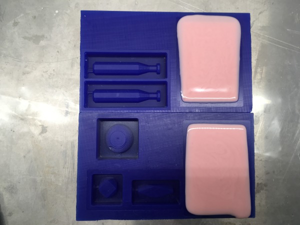
Pour silicone
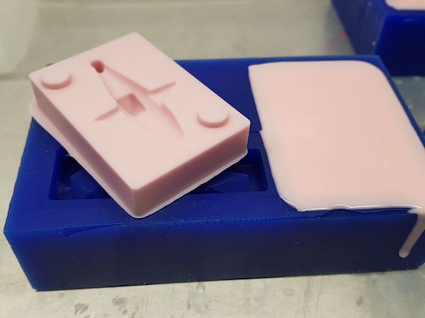
After 24 hours
Problem 3: I realised there was a problem. When I created tool path of bottom part, I deleted the convex circle on the wax mold as I described above. But it means in the second phase there is the convex circle on silicone mold. And two silicone molds cannot be attached each other because of the convex circle.. So I removed the convex circle with cutter.
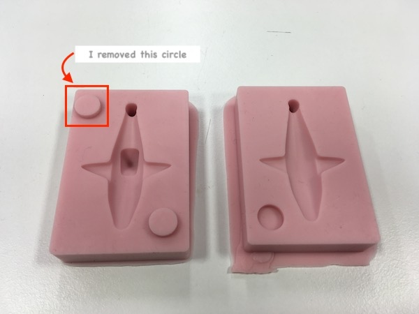
Working with chocolate
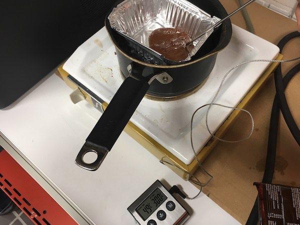
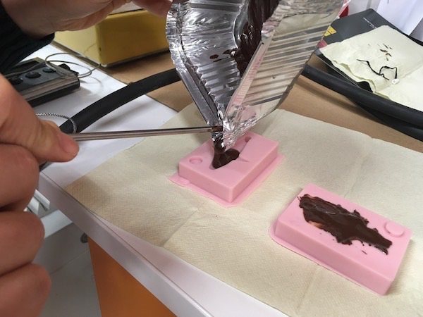
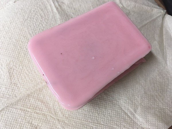
I referred to Jari Pakarinen’s documentation. According to Jari, melting chocolate is divided into three phases. I used thermometer to measure the temperature during melting to chocolate. I melted chocolate and poured into two molds and put them together. I put the molds in the refrigerator for couple hours.
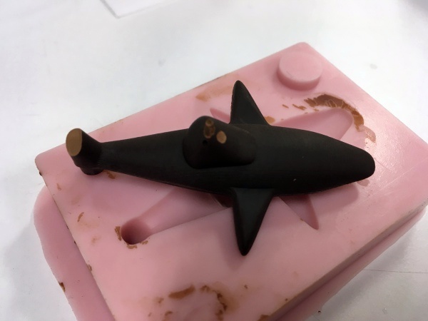
Chocolate shark
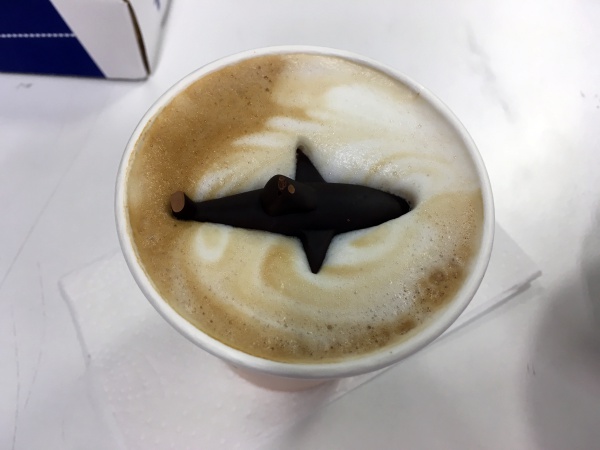
Shark in cappuccino :D
I noticed that the tail fin was not made properly. The tips of the tail fin were too thin. The parts which were not made were around 3mm. I would make all the part more than 4mm when I do molding and casting next time.
Reflection
I was confused a lot in the beginning about positive and negative model of the molds. I was still confused after I designed 3D model and had a problem also in the process but the result turned out to be good. The surface of the model was very smooth and the surface quality was definitely better than 3D printer. It requires thinking in designing phase and effort and special materials, but molding and casting have advantages compare to 3D printer. Thanks to Jari’s documentation, working with chocolate went smoothly. Next time when I try molding and casting, I would pay more attention to the size and thickness of the model to make sure the milling bit can mill properly and big enough for materials. I also could use injection to put chocolate into the mold as Ari did for chocolate casting. Another solution to pour chocolate in thin parts could be, as Bas suggested, warming up the mold when pour chocolate so that chocolate won't get hard soon when it touches the mold.
Files
Following zip file includes the top half and the bottom half of mold of the shark (STL and f3d format).

