Making echo hello-world board
Working with Eagle
I decided to use Eagle to design PCB. Eagle is under Autodesk and it is possible to download from here.
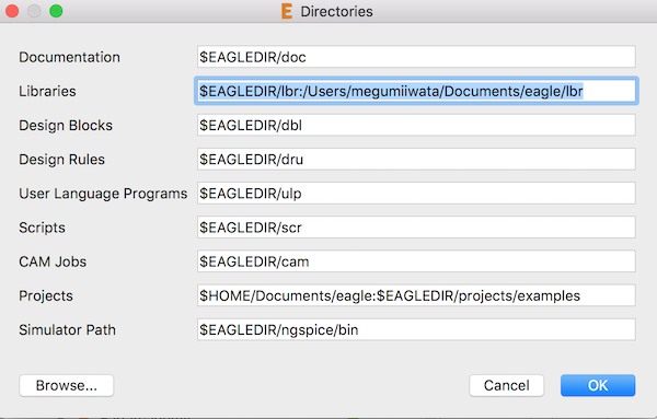
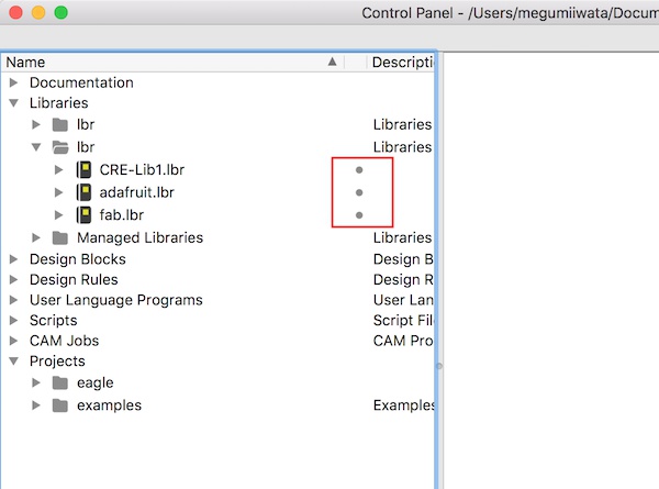
Eagle has component library but it is also possible to add libraries for additional components. I used fab.lbr. Most of the components of Fab Lab inventory are in Fab library. To use Fab library, I placed fab.lbr file in my computer (Document >Eagle> lbr). I opened Eagle, went to Option> Directories and wrote the path to the library. I activated the library by clicking the button next to the library I want to use. The button turned to be green.
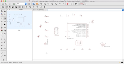
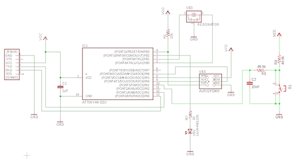
I started drawing schematic. I drew schematic of echo hello-world board referring to the board layout which was introduced in Fab Academy lecture .
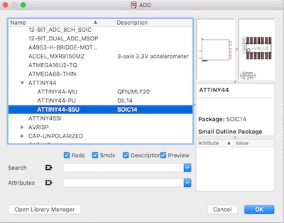
First I searched following components from libraries.
- ATTiny44-ssu (fab> ATTINY44)
- Resonator (fab)
- AVRISP SMD (fab>AVRISP)
- FTDI SMD Header (fab)
- C-EUC3216 (C-EU)
- Omron switch B3SN-3112P (fab)
- LED FAB1206 (fab)
- RES-US 1206FAB (fab>)
- Vcc (supply1)
- GND (supply1)
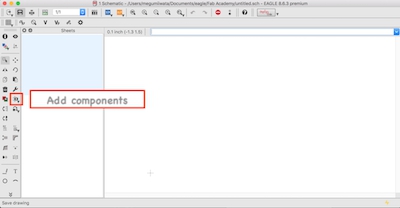
To add components, I selected a component and clicked OK. The component was added in the worksheet.
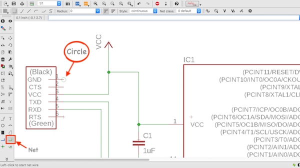
I placed the components. To move components, select Move tool and click the cross on the component I want to move, and drag it. I roughly placed the components. To connect components use Net. Make sure to start creating a connection when you see green circle on the pin of the component.
Following Antti Mäntyniemi’s advice, I put 10nF capacitor and two 49.9k resistors with Omron button switch to electrically improve push button behaviour by making push button signal clean.
I referred to Neil's example board layout to connect pins. First I connected pins for GND and VCC on each component to GND and VCC mark that I added from the library. Next I connected resonator, and MISO, MOSI, RST and SCK on ISP to ATTiny 44. The pin to be connected with each pin was written on ATTiny 44 in Eagle schematic. I connected the rest of the components with the pins which were avairable on ATTiny 44. After I created all the necessary connections between components, I added names on components and added values to resistors and capacitors.
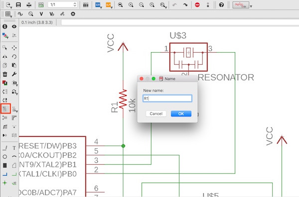
Adding name
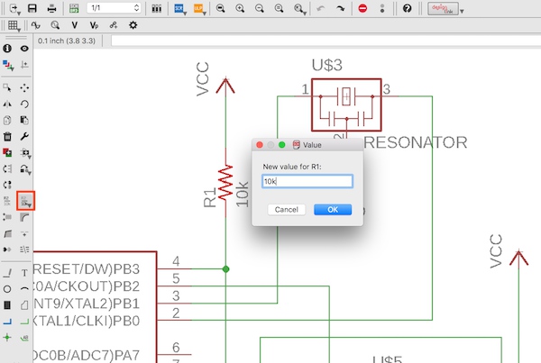
Adding value
I applied ERC (Electrical Rule Check) to make sure there is no error.
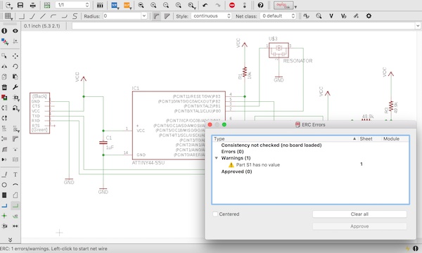
This is the final version of schematic.
I changed schematic to board layout mode.
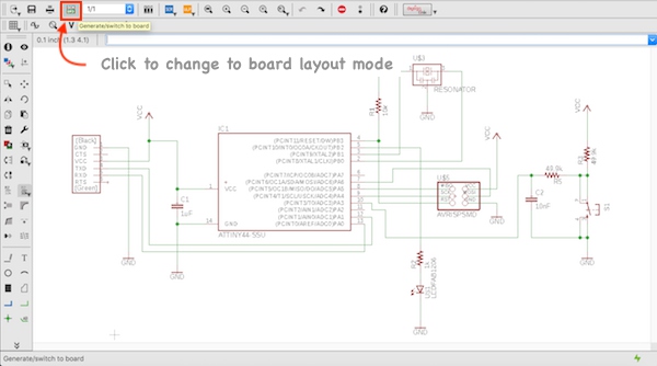
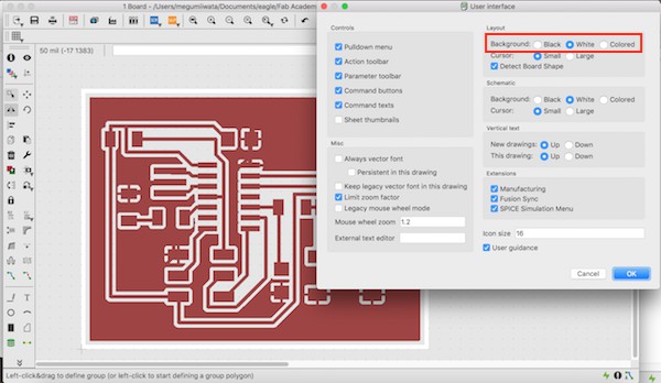
Here I designed actual layout of PCB. It is possible to change background colour (Options> User interface) or add Grid (View> Grid).
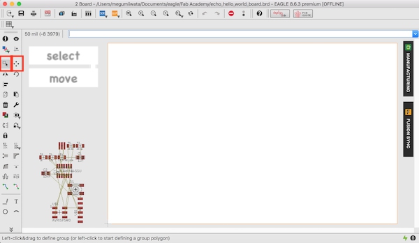
I placed ATTiny44 first, resonator next to ATTiny and FTDI to the edge. I roughly placed the switch, 49.9k resistors and 10nF capacitor on the right corner, and LED and 1k resistor on the left. I applied Ratsnest to optimise the connections between components.
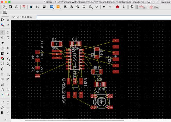
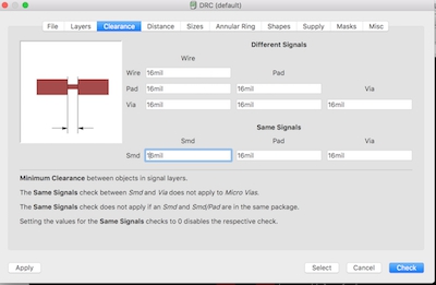
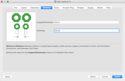
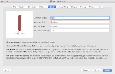
I changed isolations of wires and pads to 16mil in DRC (Design Rule Check) and clicked apply (Tools> DRC).
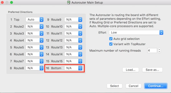
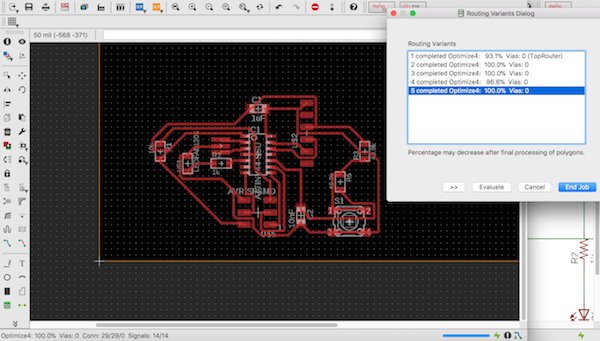
I used Autorouter to check the possibilities of routing of components. I set Bottom N/A to make the one side board. I selected the highest possibility option and checked the parts which I had to modify.
I changed the places and orientations of components and wrote command Ripup ; to cancel the wires made by Autorouter.
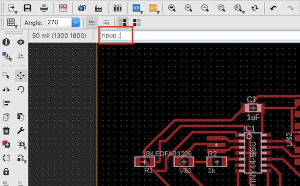
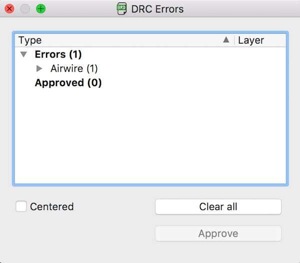
I applied Ratsnest and Autorouter again. I repeated this several times till I got 100% possibility. I checked the board layout in DRC to make sure there is no error (Tools> DRC).
Next I made the worksheet smaller by dragging the corner to the set the actual dimensions of the board.
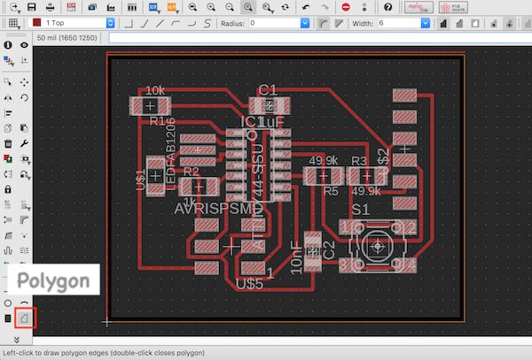
I made ground plane. I selected Polygon and drew the line around the around the worksheet.
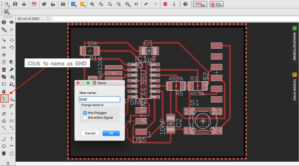
I named the line as GND by selecting Name button and clicking on the polygon line. I selected Ratsnest and the ground place was made.
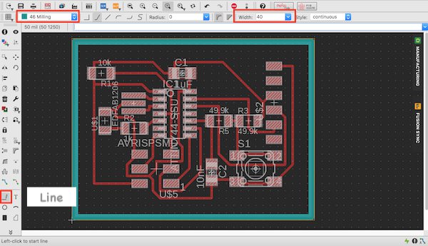
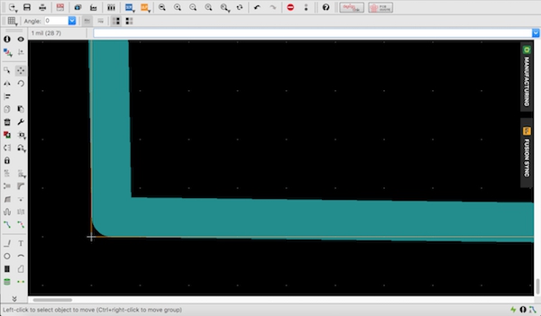
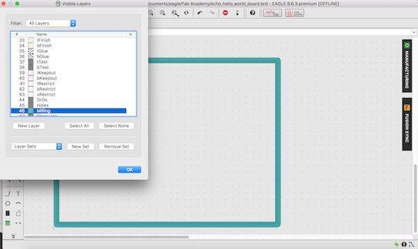
I drew outline. I selected Line, chose layer 46 Milling, set Width as 40milinch and drew line around the board. Then I zoomed in and moved the line to inside of the edge of the board by pressing Alt which allows to move flexibly.
I went to Option> Setting> Misk and unselected Display pads names, Display signal names on pads and Display signal names on traces.
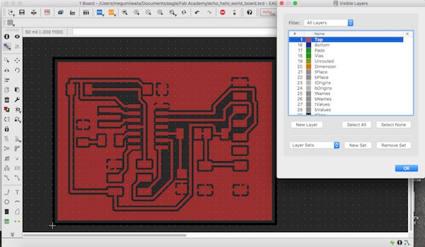
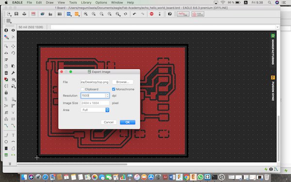
I exported trace image. I selected only top layer visible. I exported as PNG format with1500dpi, monochrome setting (File> Export> Image).
Next I exported outline image. I changed background colour from black to white. With this setting, in exported image outline is coloured as black and it will be cut. I selected layer 46 visible and exported as PNG format with 1500dpi and monochrome setting.
I checked dimension of the PNG files. I found the sizes are the same but both of the images were bigger than the actual design. I couldn’t find the reason but I changed to Windows computer and tried to export images. This time both images were correctly exported without changing dimentions.
Manufacturing the board
I followed the instructions as I explained in Week 5 to manufacture the board.
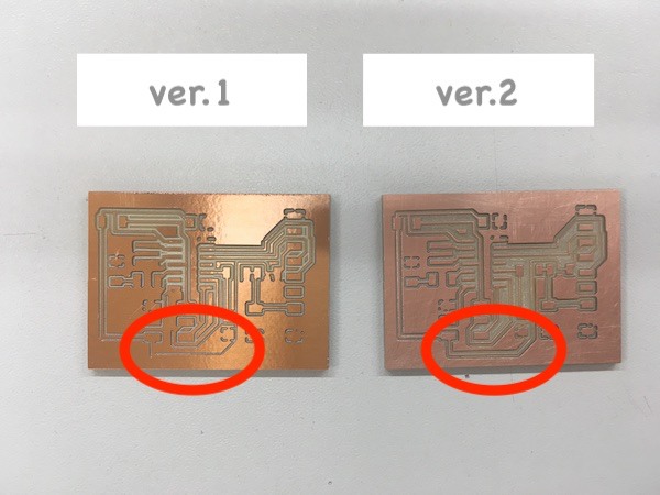
In Fab Modules, I set cutting depths 0.13mm and tool diameter 0.38mm. I operated Roland SRM-20 and cut the board. I checked the board and found some of the wires were not traced.
I changed the tool diameter as 0.36mm in Fab Modules. I checked all the cutting lines were made as cutting paths. I cut it again.
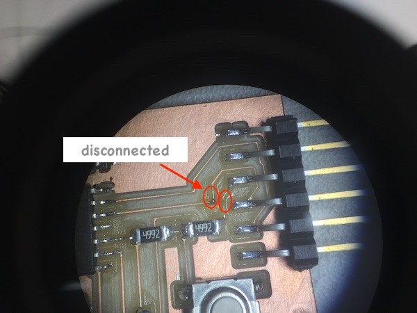
After I soldered the components, I tested with the multimeter. I used microscope and found that two of the wire was not connected. Probably the board was tilted when it was milled and some of the trace lines were very thin.
I used thin wire to make bridges to connect components. I put some solder tin on the thin copper wire and one of the component’s leg. I put the wire on the leg and heated with the iron to connect the wire on the component’s leg. Then I cut the wire into proper length and soldered to the another component’s leg.
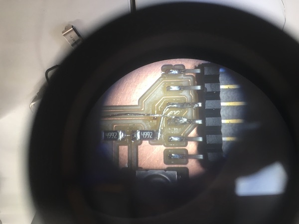
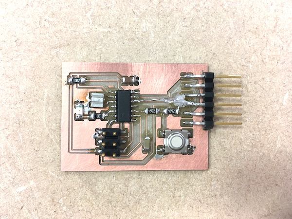
After I fixed two of disconnected parts, I tested with the multimeter to make sure they are connected. Since two bridges were crossed over, I put hot glue between them so that they will not be contacted.
Programming echo hello-world board
I followed this instruction to program the board. I also needed to have a look at instructions for Mac OSX.
As AVR development toolchain, I’ve already installed Crosspack in Week 5 to program my programmer.
I opened Terminal, changed directory to fts_firmware_bdm_v1 where my AVR development toolchain is.
$ cd fts_firmware_bdm_v1
I downloaded following files and saved it in the same folder:
I ran the command to compile the code.
$ make -f hello.ftdi.44.echo.c.make
Connect the programmer and echo hello-world board. I prepared ISP connecter. I put USBtiny to USB Hub (2.0 port) and connected with Mac. I made sure it is recognised by checking USBTiny listed in Utilities> System information> Hardware> USB. Then I connected the programmer with echo hello-world board. Make sure the orientation of the boards so that the same ISP pins on each board are connected. I connected echo hello-world board and Mac with 5V FTDI-USB-TTL-232-cable to supply power.
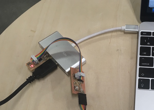
I typed the following command to set up the board for programming.
$ make -f hello.ftdi.44.echo.c.make program-usbtiny-fuses
Then I ran the following command to upload the code.
$ make -f hello.ftdi.44.echo.c.make program-usbtiny
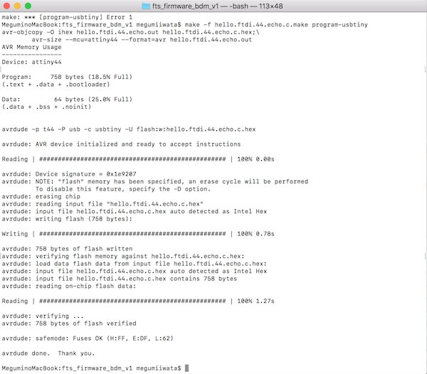
I removed the programmer. I typed the following command to import Serial in term.py.
$ sudo python -m pip install pyserial
I ran the command to run python application. I used tab key to find the USB port.
$ python term.py /dev/tty.usbserial-FT9P2WH8 115200
python application window opened, but it did not do anything. The command stopped and did not finish.
