Final project proposal
Orrery Night Lamp
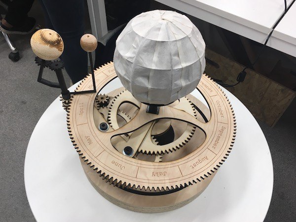
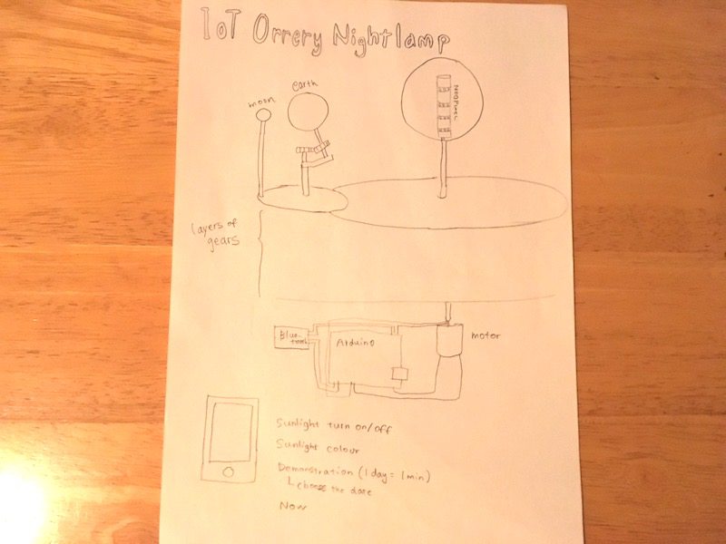
I am going to make an orrery which can be used as a night lamp controlled by a phone.
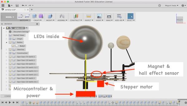
Orrery is a mechanical model of (a part of) the solar system. When I was in the elementary school, it was very difficult for me to understand why the moon changes the shape depending to the locations of the sun, the earth and the moon. It was hard to see the locations and movements from outside of where I was. This orrery shows real time locations of the earth and the moon. The earth spins and rotates around the sun, axis points to Polaris, the moon rotates around the earth. The sun has LEDs (Neopixel) inside.
This orrery will help children, like me in childhood, understand why the moon looks like that, by looking at the actual model. Also it can be used as a cool night lamp in the room. I will use Arduino as a micro controller, input will be the phone connected to Arduino using bluetooth and output will be a motor for rotating automatically and LEDs which changes the colours.
During this project, I will learn,
- How to make functional gears
- How to use Neopixel
- How to connect Arduino with a phone
- How to apply different technics to make the sun, the earth and the moon
- How to use a motor
I found some instructions of the similar projects which I would use as resources. For example:
MAKE A TELLURION (SUN-EARTH-MOON ORRERY) FOR YOUR KID,
Building an Orrery,
Adafruit NeoPixel,
ARDUINO AND APPLE HOMEKIT INTEGRATION,
Arduino Lesson 13. DC Motors.
* Update: I chose stepper motor for accurate positioning. This website:
What Is The Difference Between DC Motor, Servo Motor And Stepper Motor? was useful to choose motors for particular purpose.
I put many skills that I have wished to learn into this project, so it will be certainly a challenging project, but I will learn a lot of new and useful skills.
Related work
I have done work related to my final project as weekly assignment.
Learning about gear
I learned how gears work from following websites:
To design gears, I need to think the following points:
- Find combination of the number of gear teeth to move them together.
- Decide the size of the lamp, each the sun the earth and the moon.
- Decide the diameter of the largest gear. And generate other gears depending on the same module.
Eino Antikainen, Fab Lab Oulu staff, Fab Academy 2017 alumni helped me to design gears.
Update (15th of April): Detail description of the project (Updated version is week 19)
*This description was written before I started working on my final project in earnest. To clear the idea and the concept of the project, I answered the questions which were found in previous student Iván Sánchez milara's final project page. Updated version of questions and answers can be found in week 19.
What will it do?
Who have done what beforehand? (see above)
What materials and components will be required? Where will they come from? How much will it cost?
Structure:
- 4mm Birch plywood (gears, the sun, frame)
- Formlabs resin (the moon)
- Wood block (the earth)
- Washi (the sun)
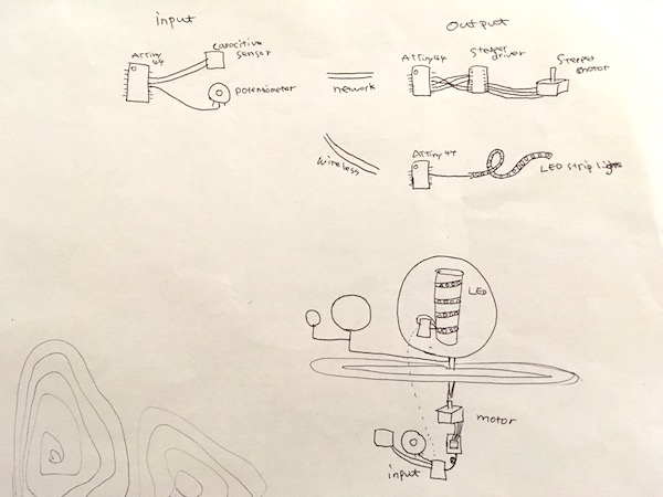
Electronics:
- ATTiny 44 (input, stepper driver, LEDs) (3)
- Resonator
- Register
- Capacitor
- PinHD2*3 (ISP)
- PinHD2*2
- PinHD1*6 (FTDI)
- Linear regulator
- Wires
Output:
Input:
- Capacitive sensor (switch on/off) (1)
- Potentiometer (speed control) (1)
What parts and systems will be made?
Structure:
- The frame of the sun will be made with plywood by laser cutting. Slicer for Fusion 360 will be used for designing. Washi will be cut by vinyl cutter and applied to cover the frame.
- The shape of the earth will be made by CNC machine and the world map will be engraved by laser cutter.
- The moon will be made by 3D printer (Formlabs).
- Gears will be designed and made with plywood by laser cutter.
- Other structure will be made with plywood by laser cutter.
Electronics:
- Microcontroller boards to control input/ output devices will be made.
Input:
What tasks need to be completed?
Structure:
- Design and fabricate whole structure, the sun, the earth and the moon.
- Calculate, design and fabricate gears. Fusion 360 gear design
Electronics:
- Design and fabricate PCBs. Think which PCB does what task.
- Connect input PCB and output PCBs.
Input:
Output:
- Fabricate PCBs for output. Draft was done in week 13
Programming
What questions need to be answered?
- Calculating gears
- How to get actual data of positions of the earth and the moon?
- How to engrave world map on a sphere? example
- How to supply power? Arduino 5V, stepper motor at least 8V. Can I supply from the same source?
- Where to place PCBs. Need to think how to wire in moving part.
What is the schedule?
Focus on electronics, input, output and programming first. Designing and making PCBs for output and input and learning how to connect them, and programming (till end of April (w15: networking and communications). Then work on designing and fabricating the whole structure includes each part, mechanics and gears.
What processes am I going to use?
- 2D design and laser cutting (the sun, gears and structure)
- 2D design and vinyl cutting (the sun)
- 3D design and 3D printing (the moon)
- 3D design and CNC machining (the earth)
- Networking (input and output connected, get data from internet)
- Input device (capacitive sensor, potentiometer)
- Output device (stepper motor, LED strip lights)
- Electronics design
- Embedded programming
Update (29th of April): 3D modeling in Fusion 360
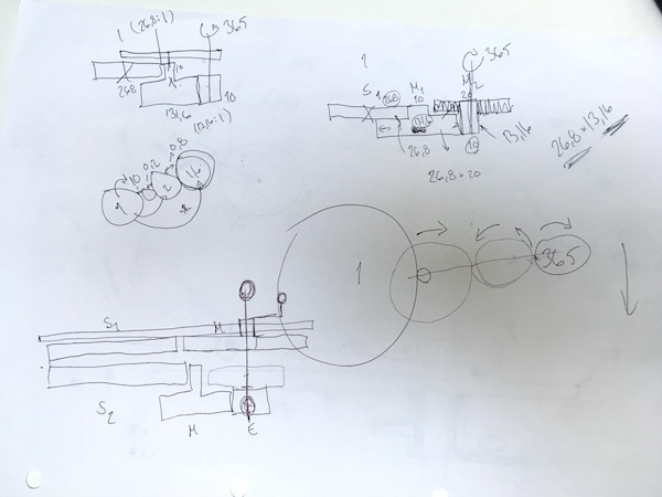
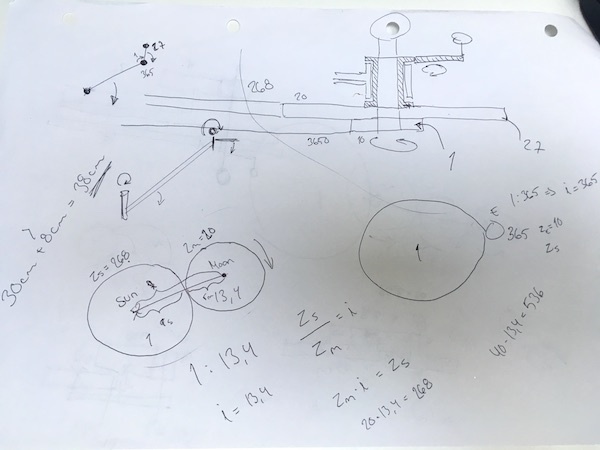
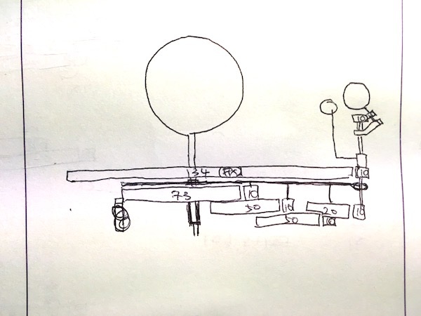
I designed the 3D model of the orrery in Fusion 360. First I started thinking about gears. The earth orbits around the sun for 365 days. So the gear ratio is the sun : the earth = 1: 365. The moon orbits around the earth 27.3 days, which is 13.4 times orbiting around the earth in a year. So the gear ratio is the sun : the moon = 1 : 13.4. I set the smallest number of the gear teeth as 10. When the gear teeth of the earth is 10, the gear teeth of the sun need to be 3650 which would be too big size difference. But I can reduce the gear size by using sets of two different size gears connected to each other. When there is axel connection between two gears (gear A, gear B), parent gear (gear P) rotates gear A, and gear A rotates gear B. When gear A is smaller than gear B, the gear ratio of gear P : gear A can be applied to the gear ratio of gear P : gear B, which makes bigger difference of speed between gear P and gear B though actually there is less size difference.
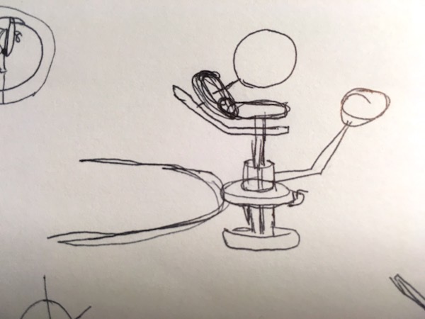
I drew sketch of gears.
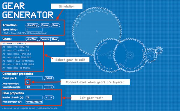
I tried Gear generator to generate gears. Gear generator allows to design gears easily. You need correct gear ratio to create gears. There is simulation function and you can download as DXF for CAD file or SVG for vector image file. I watched this tutorial video to learn how to use gear generator.
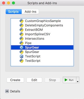
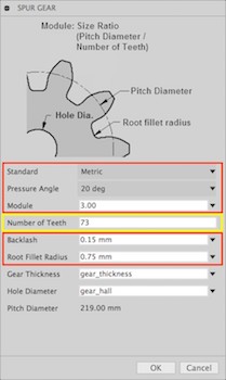
However, I could not open DXF file in Fusion 360, so I decided to use Fusion 360 add-in tool: SpurGear to create gears. I set several parameters first and started generating the gears.
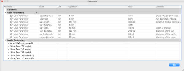
First, I set some parameters such as gear thickness, diameter of the gear hall etc.
I opened SpurGear.
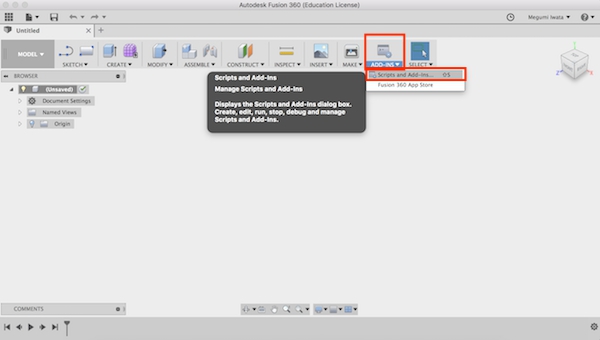
Select Add-Ins
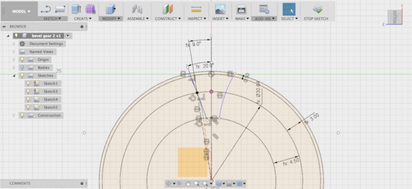
SpurGear is easy tool for designing gears and 3D modeling objects with gears in Fusion 360. You can choose settings of gears (coloured with red in the image below) and change the number of gear teeth according to your gear design (coloured with yellow). I set the settings as below referring to this tutorial video: Spur Gears in Fusion 360.
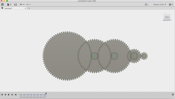
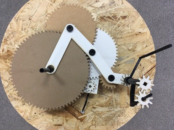
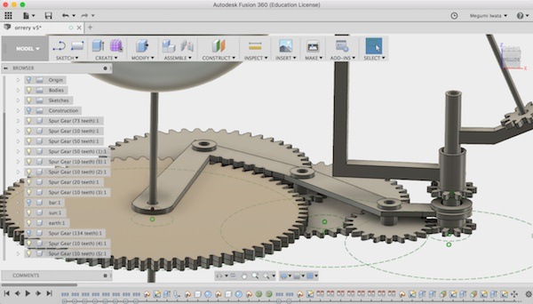
I realised that I should move the gears in a smaller space rather than placing them in a line. I decided to place them so that they will fit under the gears for the moon. I followed this tutorial video: Fusion 360 GEARS GEARS GEARS! to move the gears. I went to the sketch mode, I drew circles which diameter is the same to the pitch diameter of each gear. I drew construction line between the big circle (fixed gear) which will be attached to the sun and the smallest circle (rotating gear) which will be attached to the earth. I set sketch dimension of the construction line as same as the pitch radius of the biggest gear which orbits the moon. I used tangent (sketch palette > tangent) to attach circles each other. Then I moved the circles where they fit nicely in the smallest space under the biggest gear.
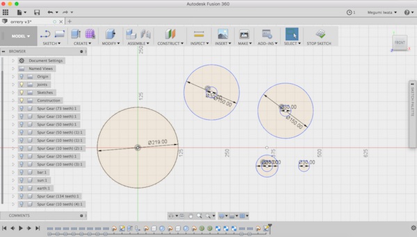
Drew the circles of the size of the gears
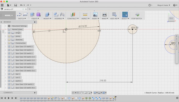
Decide the whole size of the set of the gears
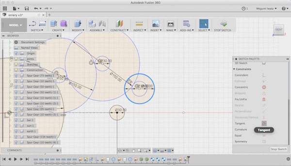
Use tangent to attach circles
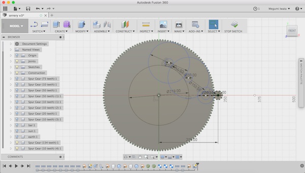
All the gears fit under the biggest gear
I went back to model mode. I used Align (Modify> Align) to place the gears where the circles were. I chose bodies as object (not component since the circle is not the component), selected the gear I wanted to move, and selected the circle where I wanted the gear to move.
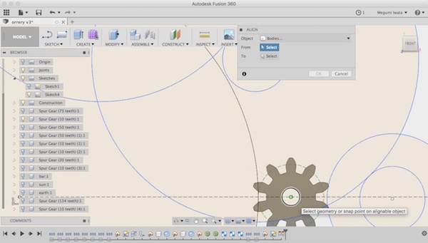
Select the center of the gear
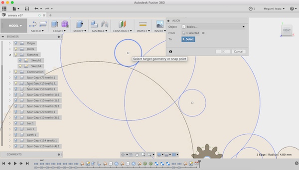
Select the circle
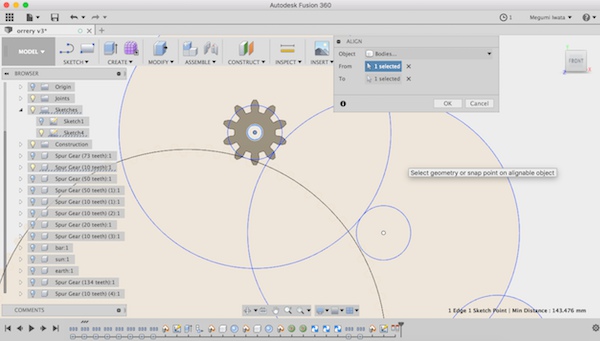
The gear moved
I rotated the gears and changed the height of the gears so that each gear fits and functions.
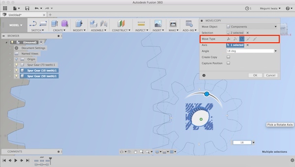
Rotate the gears: Select Move/Copy> Move type > rotate
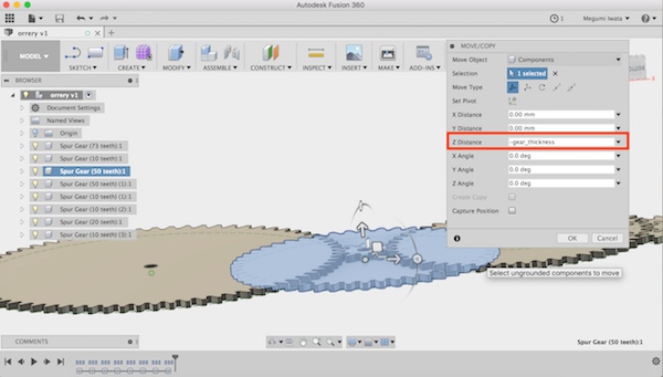
Change the height
The Earth's axis is tilted 23.5 degrees from the plane of its orbit around the sun. Referring to this instructions: MAKE A TELLURION (SUN-EARTH-MOON ORRERY) FOR YOUR KID, I decided to make a support with 3D printer to keep the earth in the certain angle. I will place the gear on the top of the straight pole which will be rotated by the other gears I explained above and attach another gear to rotate the tilted earth axis.
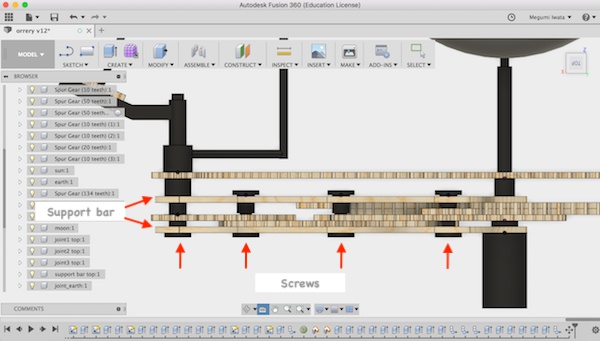
I also needed to think about how to keep the gears in their position. I decided to make a bar type of support to keep their height and position. I drew lines of the support bar in the sketch mode and extruded it. The gears need move freely from the support bar so I designed the joint which has space between the support bar and a gear which allows the gear to move freely but since the gear is attached to the support bar so gear position will be kept.
The support bar
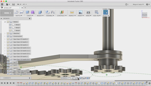
Joint
Now the first draft of 3D design of the gears is ready.
Update (9th of May): Modification of mechanical part
Eino suggested several modifications on my design. Here are the problems I had and the solutions.
Firstly, to make gears work, the gears should be attached and should not be moved separately from where they are attached. To fix the gears in the position, I made square hole on each gear and made square part on the places the gears will be attached instead of using cylindrical shape. With this design, the fixed gears will be fixed in the position while rotating gears will rotate other gears without loosening.
Joint parts will move together with the gears
The square part of joint
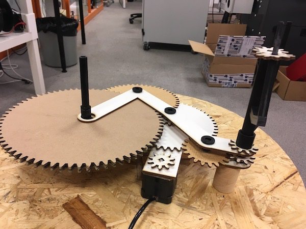
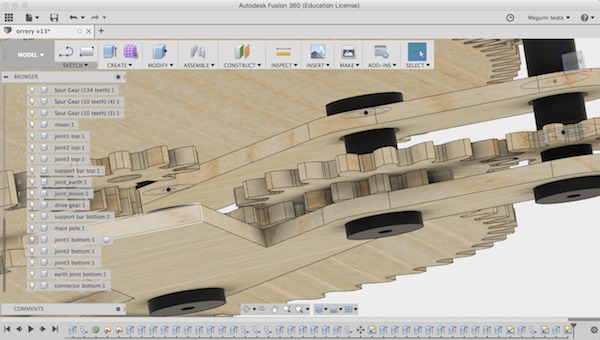
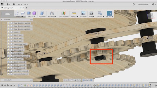
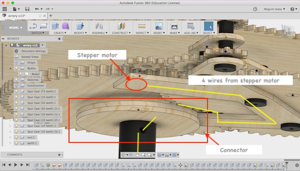
I also needed to think where to place the motor which moves the drive gear. Following Eino's suggestion, I decided to add the another support bar under the gear layers and attach the stepper motor on it. With this design, the stepper motor rotates around the fixed gears. With two support bars, the stability of gear positions will also be increased.
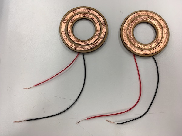
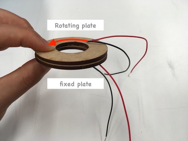
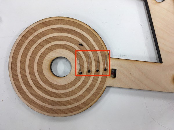
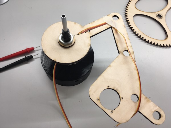
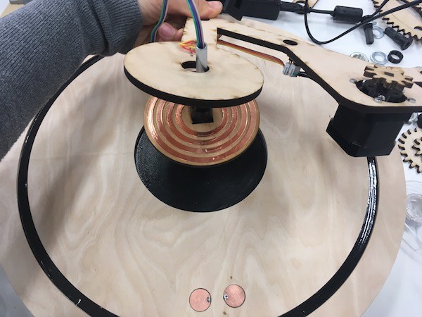
Another problem that I came across was how to connect wires from the stepper motor attached on the support bar with the controller board and power supply. Eino gave the advice to make a connector which has two parts: one is connected to the stepper motor and rotating with the support bar and another is fixed on the main pole. Using copper tape will make two parts conductive. We made prototype to test how it works. We cut two pieces of circle on which had two circles of copper tape. We connected wires on each copper circle and tested conductivity of wires with multimeter. Two wires which were connected with copper tape were conductive. I will make four copper circles on the connector and connect four wires from the stepper motor.
I had been wondering what kind of input device would be good on this final project. Fab Academy 2018 student Jari gave me a great idea to add magnetic sensor on this model. I could put the sensor on one of the fixed gears and put a magnet on the rotating part. With this design the LEDs can change the colour evey time when my birthday comes, for example.
Update (23th of May): First prototype
I 3D printed and laser cut the parts and attached together.
I found several problems.
First problem was 3D printed parts were not exactly the same size with 3D design. When I printed tall objects I laid down holizontally so that it printed quicker. But the parts were not made perfectly circle or square, but squashed a little bit. And some joint parts did not fit properly.
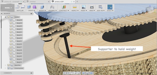
Another problem was the stepper motor was too heavy to rotate. I need to make some support which rotates with stepper motor so that it can hold the weight of the stepper motor. I will fix these problems later.
Update (29th of May): Working with Neopixel
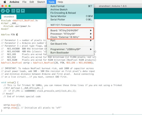
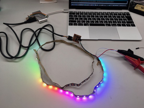
I started working with Neopixel. I read some tutorials, such as Adafruit Neopixel and GETTING STARTED WITH NEOPIXEL. I downloaded and installed Adafruit Neopixel library. First I tested Neopixel with Arduino Uno using example Arduino sketch Strandtest. It worked finely. Next I tried with ATTiny44 board I made in week 12. However, the same Arduino sketch did not work. I got to know Neopixels do not work with external 20MHz clock. So I used internal 8MHz but it still did not work. I searched documentation from previous years. This documentation was detailed and useful. I got to know that I need to use 16MHz with ATTiny44. So I replaced 20MHz resonator on my board to 16MHz resonator. After I burned bootlooter with external 16MHz, it worked. However, it only turned on 26 LEDs but not anymore.
*I could not find the reason but I assume that 27th LED was broken and the rest of the LEDs did not turn on.
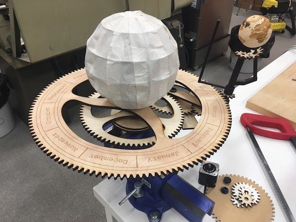
Update (31st of May): Making the sun
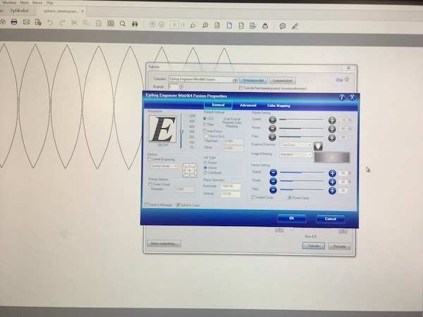
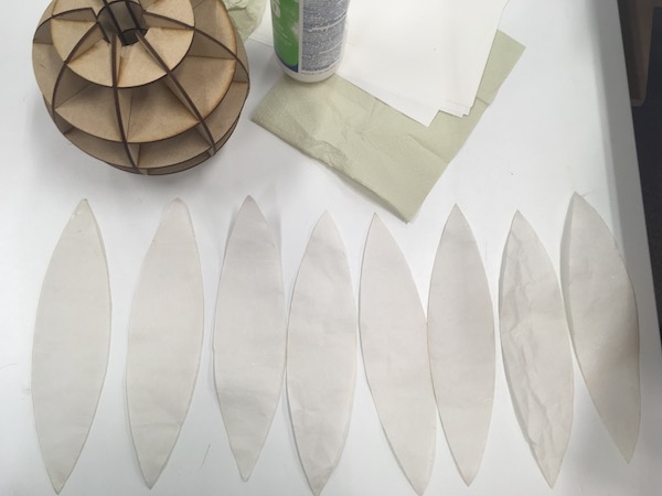
I decided to make the sun with MDF structure and washi, traditional Japanese paper, to cover the structure. I used Slicer for Fusion 360 to make structure of the sun. (detail documentation of Slicer can be found in week 4) I cut the structure with laser cutter. I searched boat-shaped unfold sphere and modified (traced image to make vector lines for cutting, removed extra parts) in Inkscape (documentation of how to use Inkscape can be found in week 3 and week 4). I decided to laser cut washi paper. Since paper is very thin and light, it is easy to be lost by ventilation of the laser cutter. So I put paper sheet on MDF board and used transfer sheet for vinyl cutting to keep paper on the board. With this way, the paper pieces were not missing while cutting.
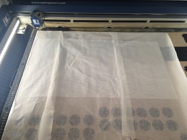
Using transfer sheet to keep thin paper on the board
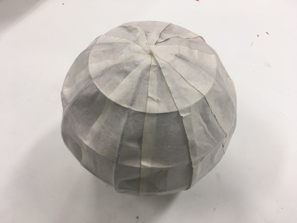
After cutting, I glued the paper pieces on the structure.
Update (3rd of June): making capacitive sensor
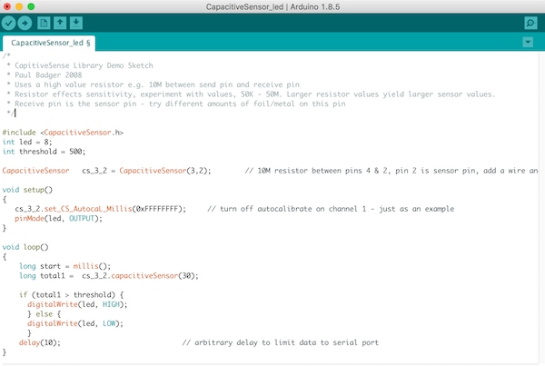
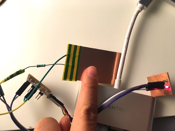
I am going to use capacitive sensors to turn on the lights in the sun and start rotating the motor. I read instructions of how to make capacitive sensor, such as Capacitive Sensing Library and ARDUINO TUTORIAL: CAPACITIVE TOUCH SENSORS. I downloaded and installed Capacitive sensor library for Arduino. Capacitive sensor needs two pins, sending pin and recieving pin. I made very simple capacitive touch sensor with copper laminated board for PCBs to test the sensor and library. I used 1MΩ resistor between sending pin and sensor.
I used the example code from the capacitive sensor library for testing. In serial monitor, I checked the values from the sensor. I set the threshold as 500 and modified the example code by adding commands to turn the LED on when the sensor value is bigger than threshold. The LED turned on when I touched the sensor.
Update (4th of June): modifying 3D model
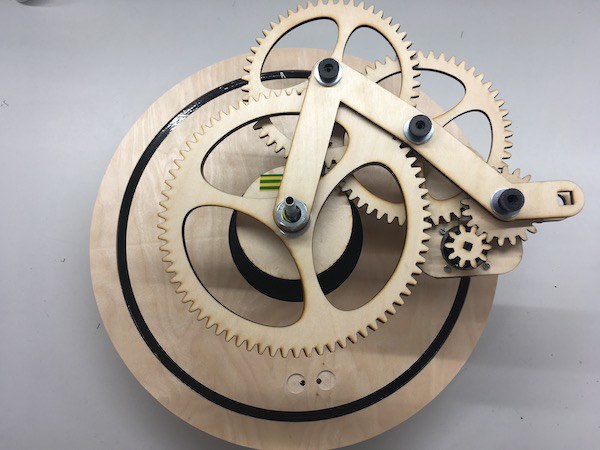
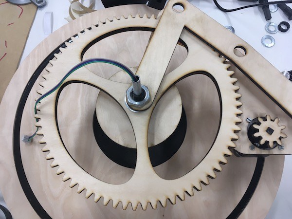
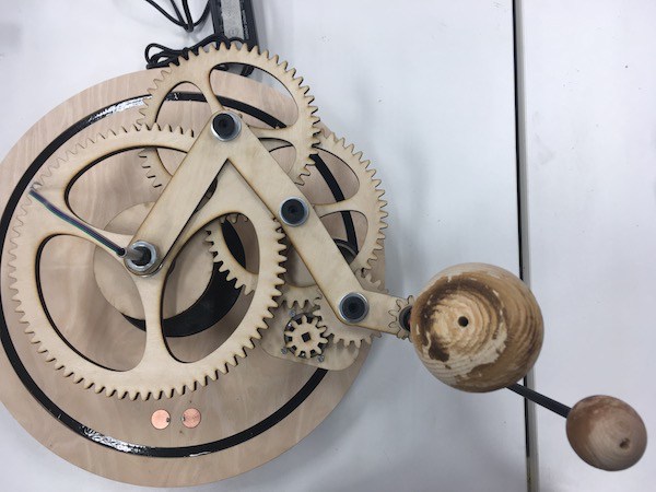
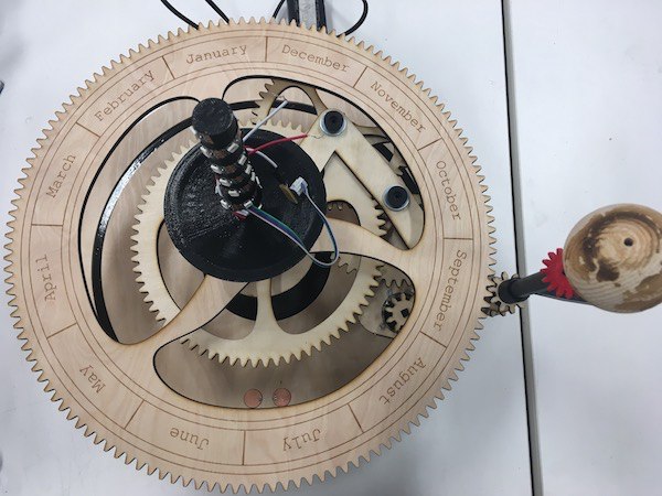
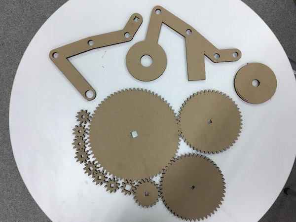
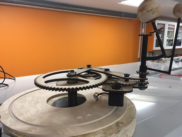
I cut the gears with 4mm plywood and assembled the parts together.
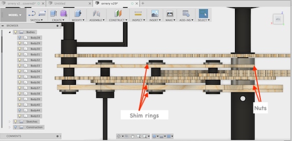
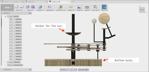
I modified 3D model of my final project based on the problems I found. The major problem was that the gears were not rotating smoothly. It was because 1) friction between gears interfered smooth rotation and 2) height of the whole rotating parts were not holizontally equal. Main points of modification were: 1) adding space for shim rings (washers) to reduce friction to rotate geares smoothly, 2) support to hold weight of the rotating parts to keep the height of the rotating parts equal. Also I decided to use nuts to keep the fixed part stably.
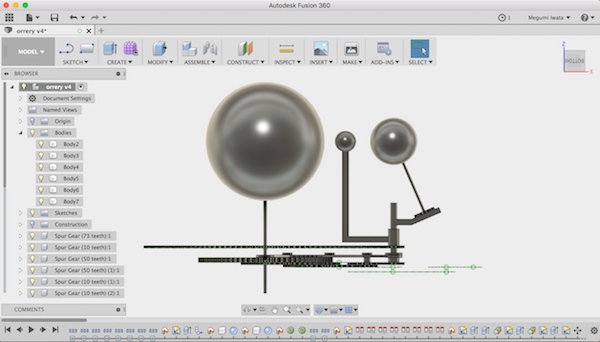
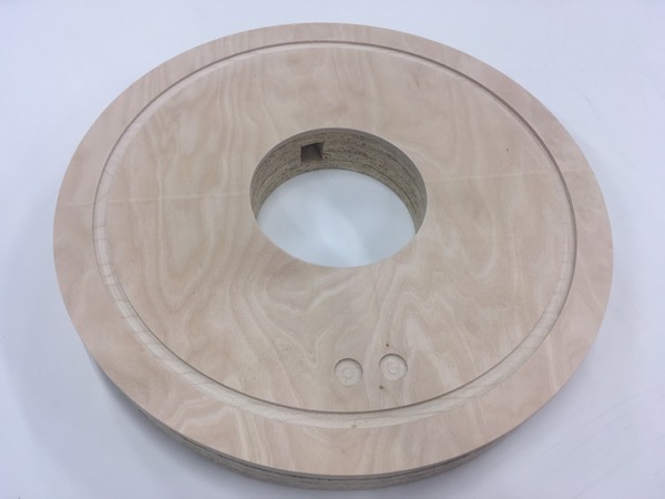
I designed the bottom body under the orrery to hold the weight and keep balance of the whole body and the part to keep the sun.
I decided to make the bottom body with four layers of 11mm thick OSB that I used in week 8 and 6mm plywood on the top. I decided to store all the PCBs in the bottom body so I made the holes for the cable for powering and capacitive sensors which will be on the top layer of the bottom body. I used CAM mode in Fusion 360 to create tool paths for CNC machine as I did in week 8. I made joint parts to connect layers of OSB and used dogbone so that the milling bit can create rectangular holes properly. In week 8, I used 8mm flat milling bit, and the dogbones were not made properly because the diameter of the bit was too big. This time I used 6mm milling bit.
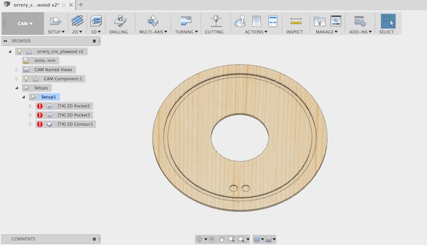
Top layer with plywood
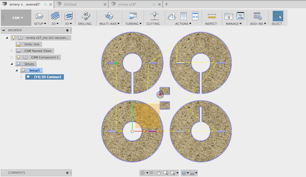
Bottom layers with OSB
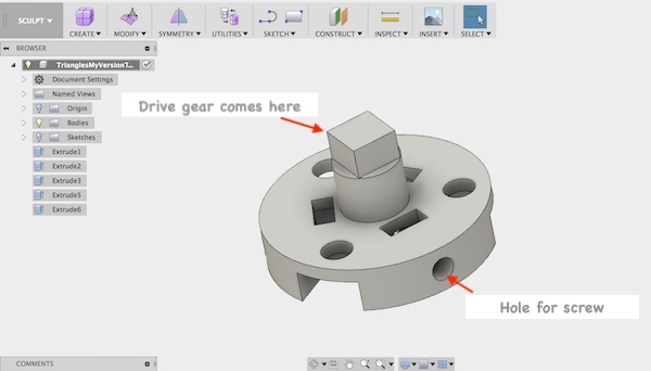
Attaching the stepper motor
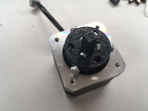
Considering the weight of the stepper motor, I used 6mm plywood for support bar where the stepper motor will be attached instead of 4mm plywood. From experience of working with stepper motor in machine weeks, I knew that joint part between the stepper motor shaft and the drive gear is very important. Ari Vuokila, Fab Academy 2018 student from Fab Lab Oulu, designed really good joint for stepper motor shaft. I added the square part on the top where the drive gear will be attached.
Update (5th of June): Manufacuturing bottom body
I made bottom body with CNC machine. The detailed operation process of CNC machine can be found in week 8. I used 6mm flat milling bit for making pockets and contouring as I planned. With 6mm bit, dogbones were made nicely. After cutting, I sanded with sanding machine and by hand. I used two pieces of OSB as joints to connect OSB layers.
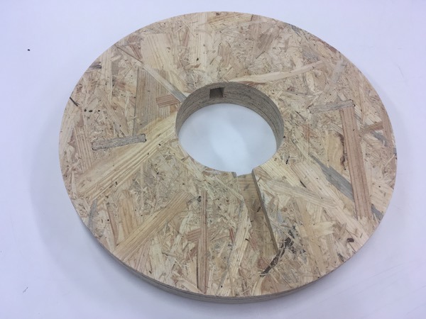
OSB were layered with two joint pieces
Top layer has the route for support for the weight and places for capacitive sensors
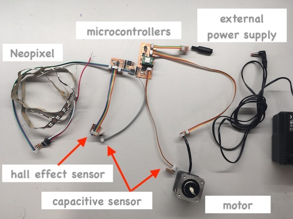
Update (6th of June): Organising PCBs and wires
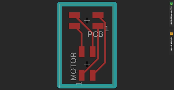
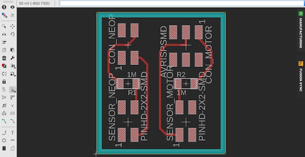
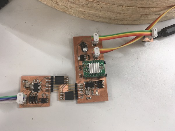
I use two boards for my final project. One is the board I made in week 12 for LED strip lights (Neopixel), hall effect sensor and capacitive sensor 1 to turn LEDs on. Another one is the board I made in week 13 for stepper controller and capacitive sensor 2 to activate the motor. The power (9V) will be provided to the board for stepper controller from external power supply. The board has the regulator and provide 5V to the boards to the other board. I decided to make small PCBs to connect each other.
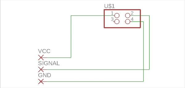
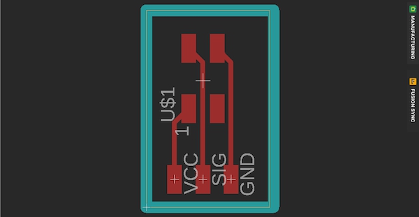
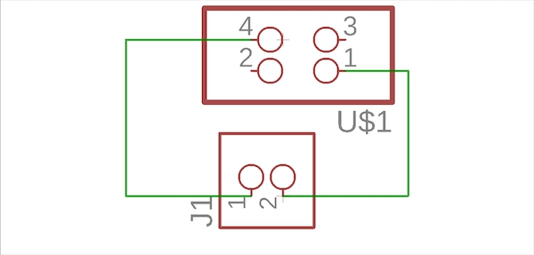
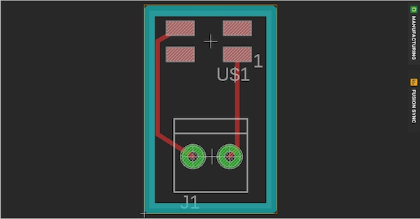
I designed and milled mini connector boards to organise PCBs and devices.
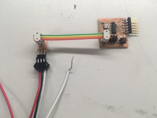
The board to connect the stepper motor and motor controller board.
The baord to connect LED strip lights and microcontroller board.
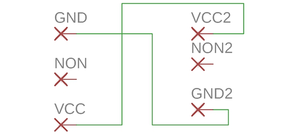
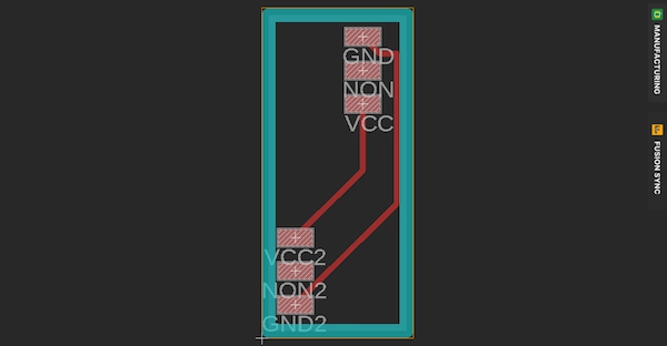
The board to supply 9V from extra power supply to the stepper controller baord.
The board to connect the stepper board and microcontroller board for providing 5V.
Here are the mini connectors for each device.
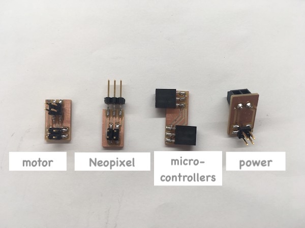
Connector between microcontrollers
Connector between microcontroller and neopixel
Now all the devices are connected with wires.
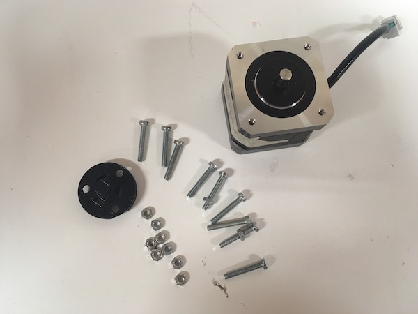
Update (7th of June): Connecting the stepper motor
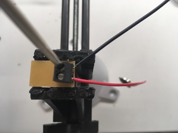
The stepper motor is going to be attached on the support bar which rotates around the sun. I used 3mm diameter screws to fix the joint part on the motor shaft and to attach on the support bar.
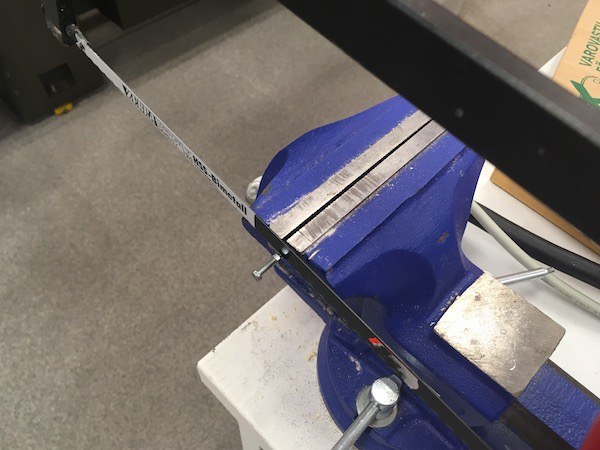
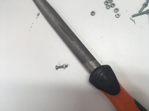
The screws were too long so I cut the screws with the saw. Eino Antikainen gave me an advice to cut the screws nicely. I marked the line on the right length and put a nut. I cut the screw and sanded it. When I cut and sand the screw, some of its flutes were squashed. While taking the nut off from the screw, the shape of the flutes were fixed.
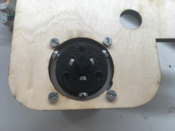
I put nuts in the small spaces near the middle on the joint part, and screwed from the side. The joint part was tightly attached on the shaft of the motor. Next I screwed the motor on the support bar.
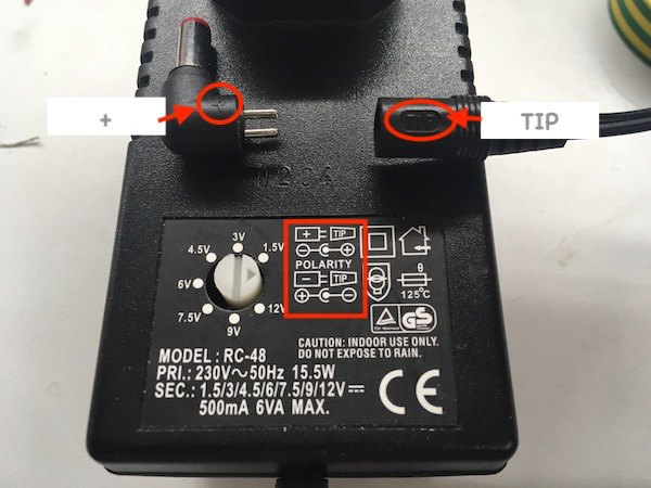
Update (8th of June): Powering
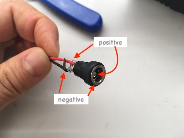
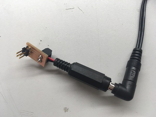
I used exernal power supply for powering. On the head of the external power supply, there are inner and outer parts which are conductive. The head is detachable and can be changed which part, inner or outer, are negative and positive depending on the female connector. The description was written on the body of the external power supply.
I soldered the black and red wires on the female connector. I put the other end of the wires in the terminal block on the PCB. I tightened the screws and fixed the wires.
I tested the connection with multimeter to make sure the positive and negative were correctly connected.
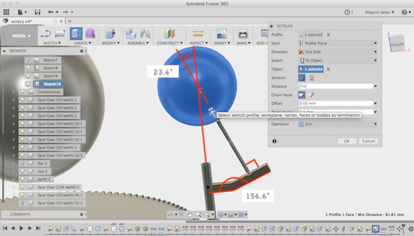
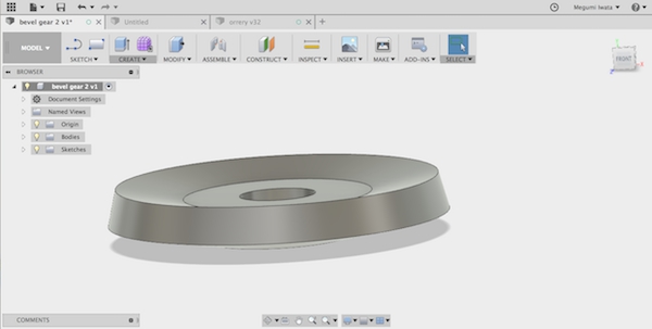
Update (10th of June): Designing bevel gears
I had a problem rotating the gears. The gears on the tilted pole for the earth did not fuction well because of the angle. I decided to make two bevel gears with the same number of teeth which will be attached in the certain angle, 23.4 degrees. There is an app: Bevel Gear Design for designing bevel gears in Fusion 360. Currently it works only on Windows OS. I downloaded and installed in a windows computer in the lab. But I realised that it has limitations on designing, such as it only allows to design bevel gears which shaft angle is 90 degrees, or it allows only certain numbers of gear teeth and modules. So I decided to design bevel gears by myself. One of Fab Lab Oulu staff, Tapio Korpela gave me advices for designing bevel gears.
I referred following websites for designing gears and calculating dimentions:
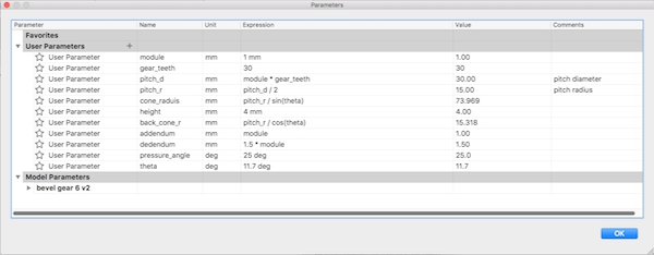
First I calculated the dimentions of the bevel gear and added parameters in Fusion 360. Following the tutorial videos as I listed above, I drew a sketch of the gear.
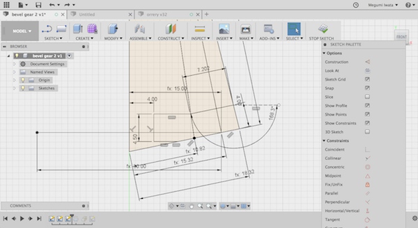
I stopped the sketch and revolved the sketch. I created construction plane on the surface in the image below (Construction> Tangent plane to face at point).
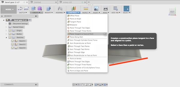
Select this surface and create construction plane
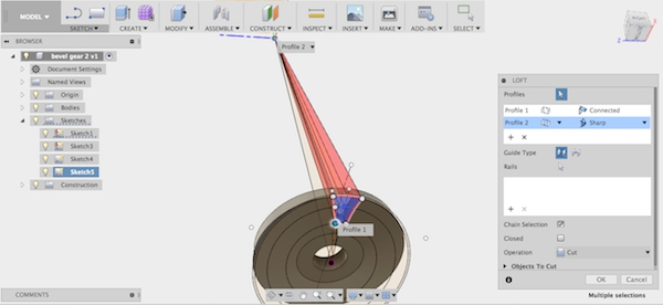
I selected the tangent plane, and drew sketch of the teeth following the tutorial videos that I listed above. I stopped the sketch, selected the area I drew, and used Loft to cut out the area (Create> Loft).
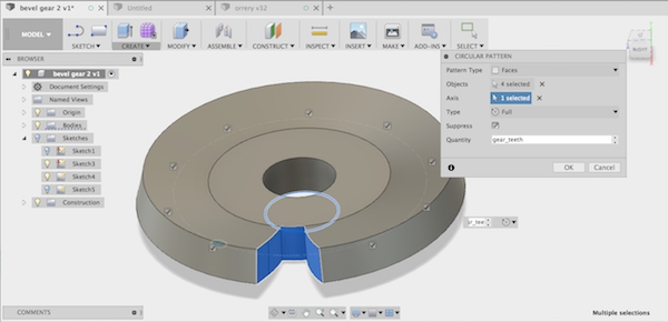
I selected the faces of the area that I cut out, and used Circular Pattern to create teeth (Create> Pattern> Circular Pattern).
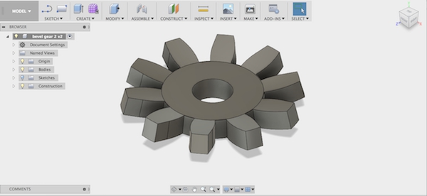
I created 10 teeth on the gear, but later I got to know 10 teeth is not enough for bevel gears to have enough curve and angle on the teeth for proper function. The bevel gears on my design will not be functioned with any other gears, but only these two bevel gears. One bevel gear will have axel connection with one of the gears which rotates the bevel gears. In this case, I can use separate gear teeth number and modules from other gears. I reduced the gear module and increased the number of the teeth, while keeping pitch diameter. I made 15 teeth bevel gears and 30 teeth bevel gears and 3D printed. Both gears functioned properly.
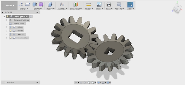
Bevel gears with 15 teeth
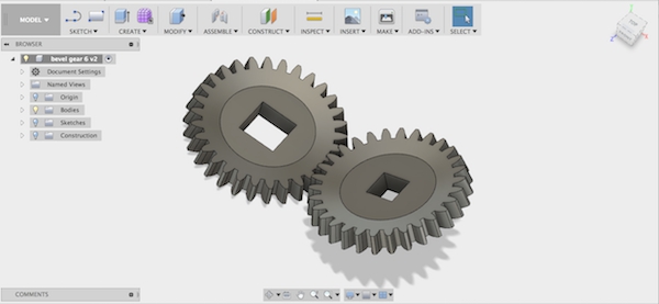
Bevel gears with 30 teeth
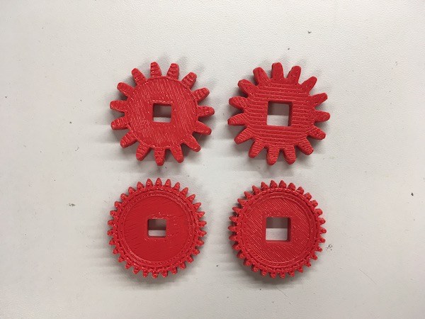
3D printed bevel gears
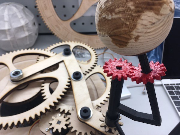
Bevel gears attached on orrery
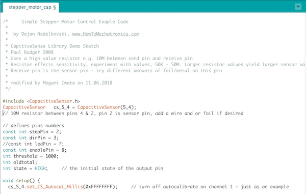
Update (11th of June): Programming (capacitive sensor - Neopixel and stepper motor)
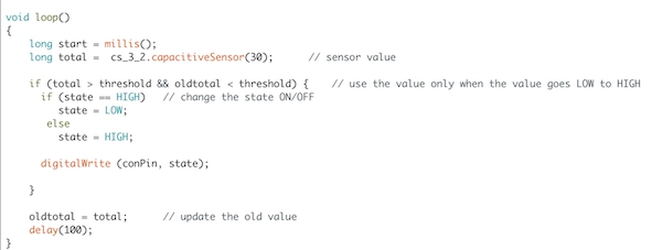
I referred to this Arduino tutorial: Arduino - Switch to make the switch with the capacitive sensor. I measured the sensor value and set the threshold. The basic idea of the code for the capacitive sensor as the switch is that I defined state, and wrote the code which changes the state when the condition happens. I also defined oldtotal which represents previous sensor value and set the condition to switch the state as "when the current sensor value is bigger than threshold and the previous sensor value is smaller than threshold". With this condition, the condition happens once, even though the sensor is coutinuously recieving bigger values than the threshold while I am touching the sensor.
I used enable pin on the stepper controller to use the capacitive sensor as switch. When I designed the board in week 13, I did not use enable pin. I added the wire from enable pin on the stepper controller to the pin on ATTiny44.
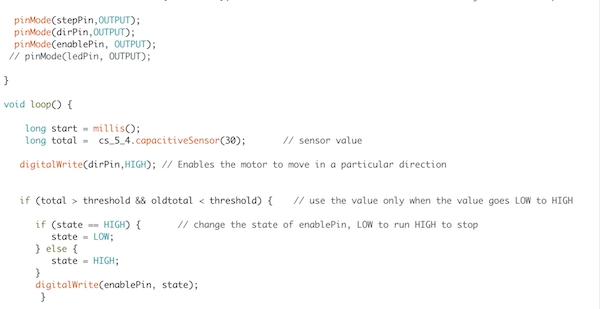
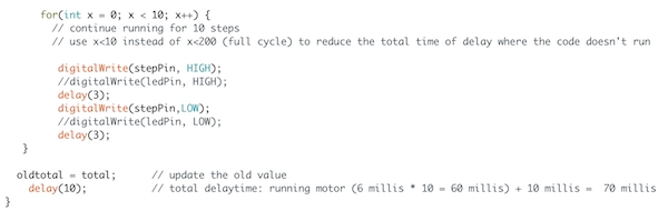
Here is the code for stepper motor and capacitive sensor. It changes the state of the enable pin when the condition happens.
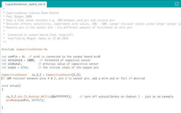
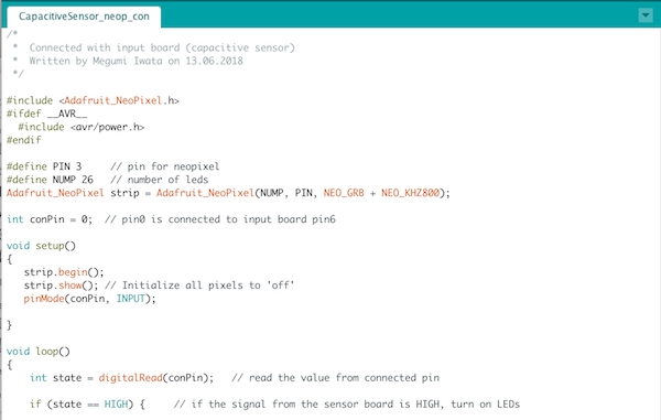
ATTiny 44 doesn't have enough memory to use both Neopixel and capacitive sensor libraries. So I decided to use two boards, sensor board and Neopixel board and connect them. I used ATTiny44 board that I made in week 12 as sensor board and ATTiny45 board that I made in week 15 as Neopixel board.
I connected VCC, GND and one signal pin on each board. I wrote the code for the sensor board which changes the state of the connected signal pin. For the Neopixel board, I wrote the code which turn on/ off depending on the connected signal pin's state.
Here is the code for the capacitive sensor board.
Here is the code for Neopixel board.
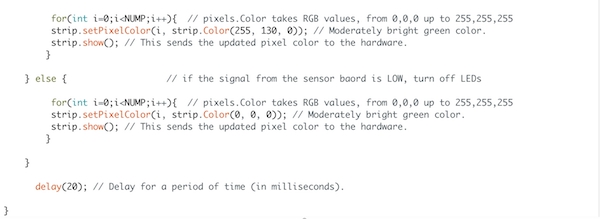
Later I noticed unexpected behaviour. When I truned the yellow lights on, Neopixel stoped lighting and the motor started rotating automatically. I checked the current, the motor consumed about 550mA and Neopixel consumed about 510mA. The maximum output current of external power supply I use is 3A when 9V is supplied. However, the maximum current of the regulator I use is 1A. When the yellow lights was turned on, it hit the current limit and Neopixel stopped lighting automatically. I changed the color to brownish red which consumes less current.
Update (12th of June): Vinyl cutting copper sheet
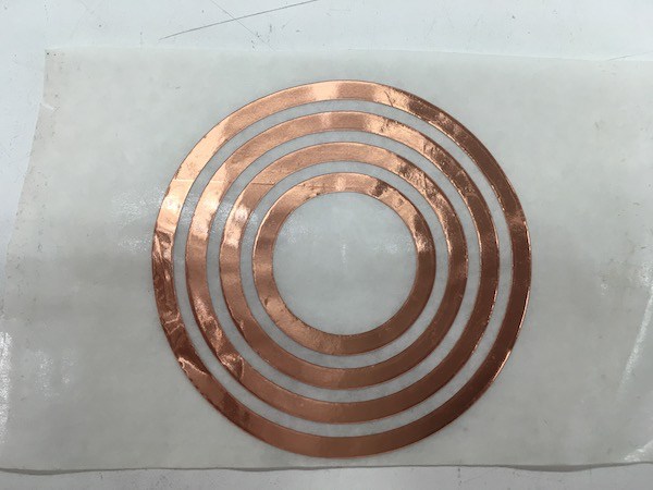
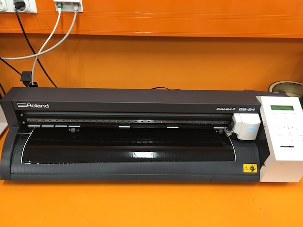
As I described earlier, I needed a connector to connect wires from the stepper motor on the rotating part to the PCB which is going to be placed in the fixed part. I decided to cut copper sheet with vinyl cutter to make four conductive circular lines on the connector. I drew circles with four different sizes in Inkscape. I set the document size as same as content size. I set up the vinyl cutter (detailed documentation of operation of vinyl cutter can be found in week 4). I set the cutting area only slightly bigger than the object size by placing the wheels to hold the copper sheet. I chose Edge in the menu. I selected Print> Properties in Inkscape and selected Get from machine to set the cutting area. I changed the length of the cutting area slightly bigger than the object size.
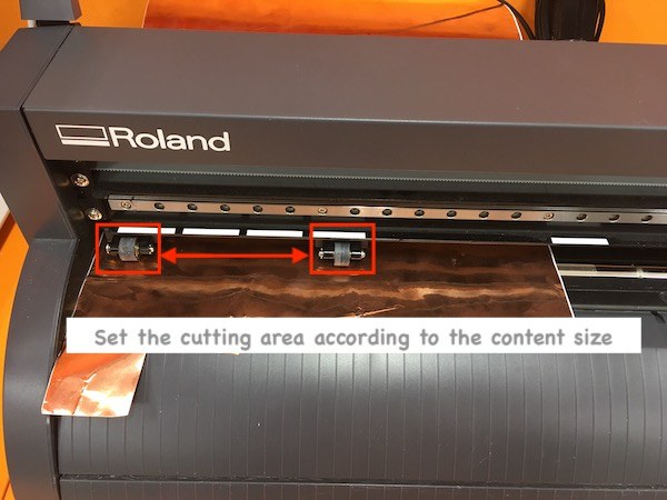
The copper sheet on the vinyl cutter. Set the cutting area
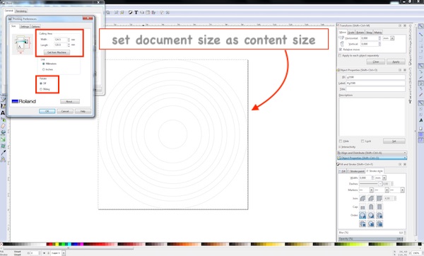
Get information of the cutting area from the machine, rotate 90 degrees if needed.
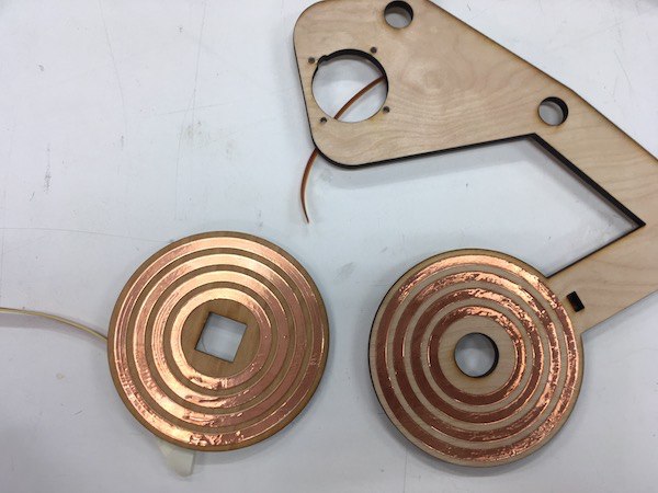
I cut two sets of four circles to put them on the rotating plate and fixed plate of the connector.
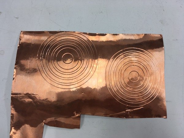
I cut four wires and placed on the four circles on each plate of the connector through the small holes.
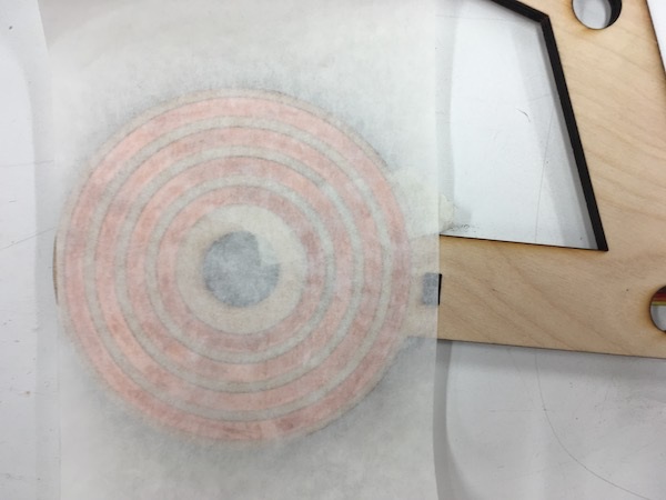
I applied transfer sheet and attached the four circles on the surface of each plate of connector.
After I made both rotating plate and fixed plate with four conductive circles, I put the surface of each plate together and checked the conductivity with multimeter.
I also cut the vinyl sheet to put on the top surface of the bottom body for the smooth rotation of the support wheel which is going to rotate together with gears. It reduces the friction on the surface of the plywood.
Update (13th of June): Making capacitive sensors
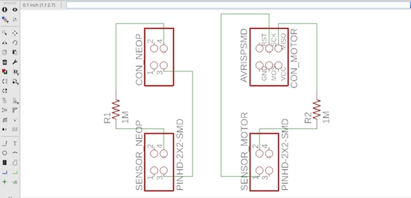
I made capacitive sensors with copper laminated board which is used for PCBs. I designed circles in Eagle and milled with Roland SRM-20. I also made a PCB for connecting capacitive sensors with the sensor board with 1MΩ resistors which are needed for capacitive sensors.
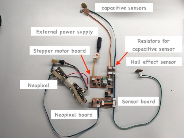
Here are all the boards and electronics of my final project.
Update (14th of June): Assembling
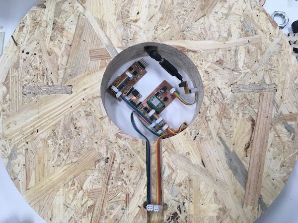
I assembled parts of my orrery. First I connected all the PCBs and connetion boards together and placed them into the bottom body. I connected the cable of the external power supply with stepper controller board through the space on the bottom body. I placed capacitive sensors on the top of the bottom body.
Connector with copper circles and bottom support bar were added. Fixed gear and top support bar were added and fixed with nuts.
All the gears were attached. The earth and the moon were attached on the edge of the support bars with gears. Neopixel was attached on the pole with double-sided tape. Through the hole on the pole, wire from the PCB was connected with Neopixel.
Support wheel was attached with screw. All the joint parts were also screwed in.