Moulding and Casting
Week 10

This week's assigment is simple: make a mold and cast a part. But my difficulty was finding the inspiration for the object to be made. Presently, I do not have a need for casting something in my project but that may change in the future. After a few false starts, I finally made a simple flywheel that I think I will be able to produce a few cast samples.
First try.
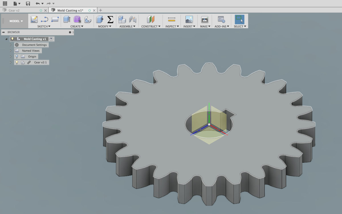
My first idea was to make a gear. Since we are using a CNC machine and Fusion for making the mold we have to make a simple one side mold. The idea is to start learning with a simple one side mold than go on with more complex projects later on.
Making the gear was straightforward, having found a tutorial on Youtube.
When simple ideas turns out to be quite complex
I was prepared that my idea would not make a perfect gear: after all, gears are machined, rarely molded. And since I'm making a one sided mould, I thought that it would make a nice decorative gear. But it turns out that I knew that a gear had many faces, but all those faces needs a slight angle to pull out the part from the mold, normally a 3° angle, called the draft angle. Trying to add all those draft angles to the gear part proves out to be possible but I realised that the mill that I use (.125 inch) can't precisely mill the entire tooth profile and the sharp angle. I had to find another idea.
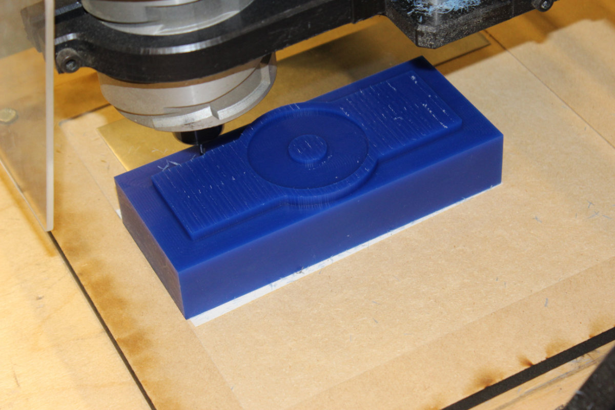
The next idea that I tried was a medallion with my name and, if time was available, the names of the Fab Academicians here at échoFab. The wheel was easy to make but I hit a wall with the letters. Fusion has an engraving tool but it is not made to follow a vector path. You can make it to follow a path using Inkscape but the transfer is far from perfect: once imported, you need to move the letters, flip them and scale them down. For such a small part, this tweeking is tedious and almost impossible to complete. Although we can write letters in Fusion, those words are on one line. Fusion is not an imaging software. I had to change my project, again.

Third time's the charm
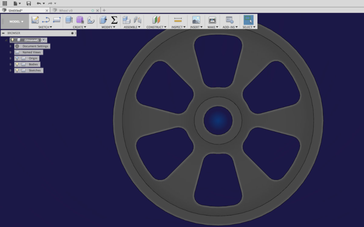
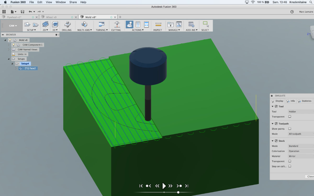
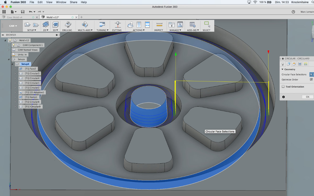
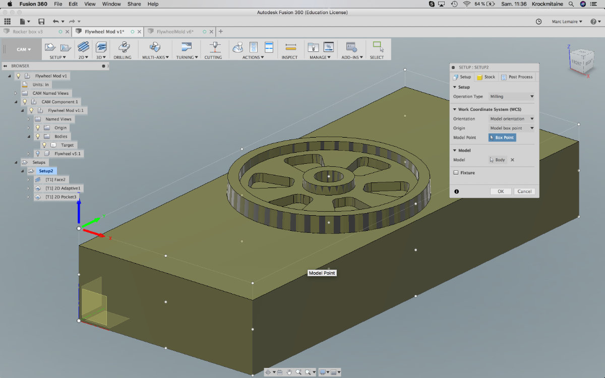
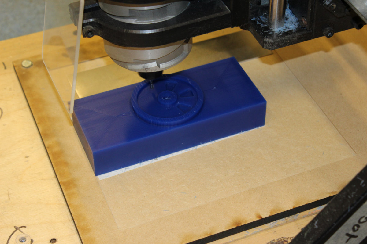
The third and what turns out to be the best idea was to make a flywheel. I started with the wheel of a ½" depth, added a web with some empty holes. The draft angles were quicly added, made the mold and included as a link the flywheel. But during simulations, I ended up with lots of errors. I deduced that those errors were generated by the fact that the mill was at it's limits. I looked up the speck and saw that the mill height was .500", thus the warnings. I had to modified the flywheel to a more conservative depth: ¼". I quickly modified the file and was done with the profile.
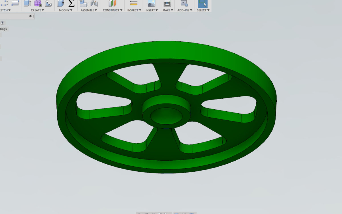
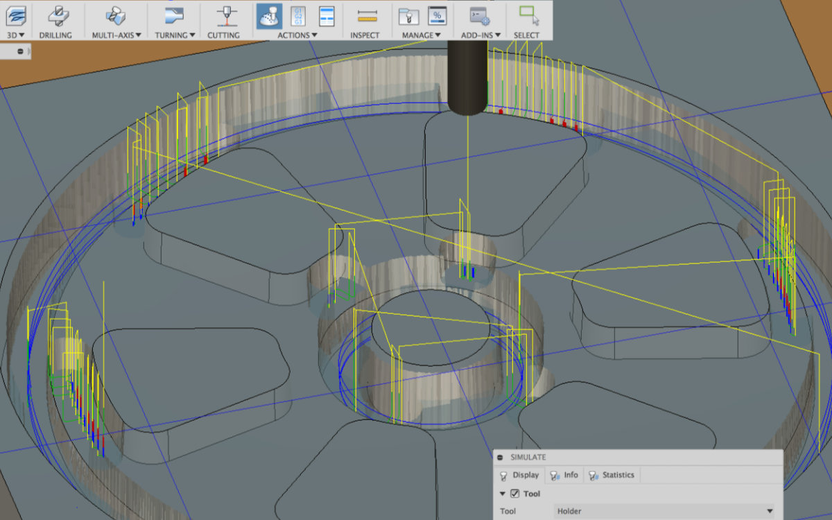
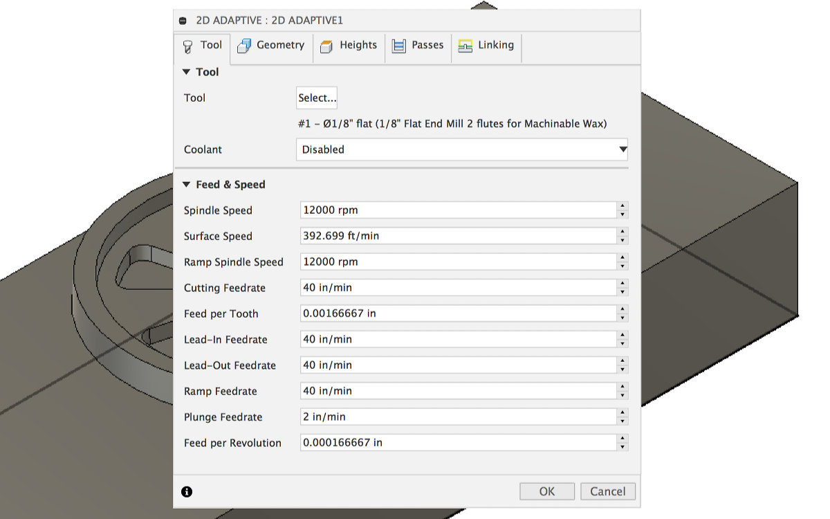
I made some simulation but I still had the problems with the mill going to the full depth. The tool was always making the towers for the holes but tried as I might, I could'nt force it to mill the two flanges. As I was looking at the menu, I saw that there was an option under 2D "Circular". I read the description and it looked like this one would fill my needs. I tried it first with the two vertical surfaces of one circular pocket but somehow, the mill ended up going on rapid cycle through solid mass. I corrected the problem by milling the four faces of the pockets independently. I was satisfied but still didn't seemed right. By carefully looking at the description of circular pocket, I decided to try milling two exterior faces and this worked quite well. So I replaced the preceding four operations by only two. I also divided the multiple height stepdown by .04" to ease stress on the endmill. I still have warnings that the tools is hitting the surface too hard when the mill is plunging while doing circular milling but after consulting with Mathieu, we think that the mill will stand the stress. The timeline for the milling operation is now a modest 12 minutes.
Of being prepared (or lack thereof)
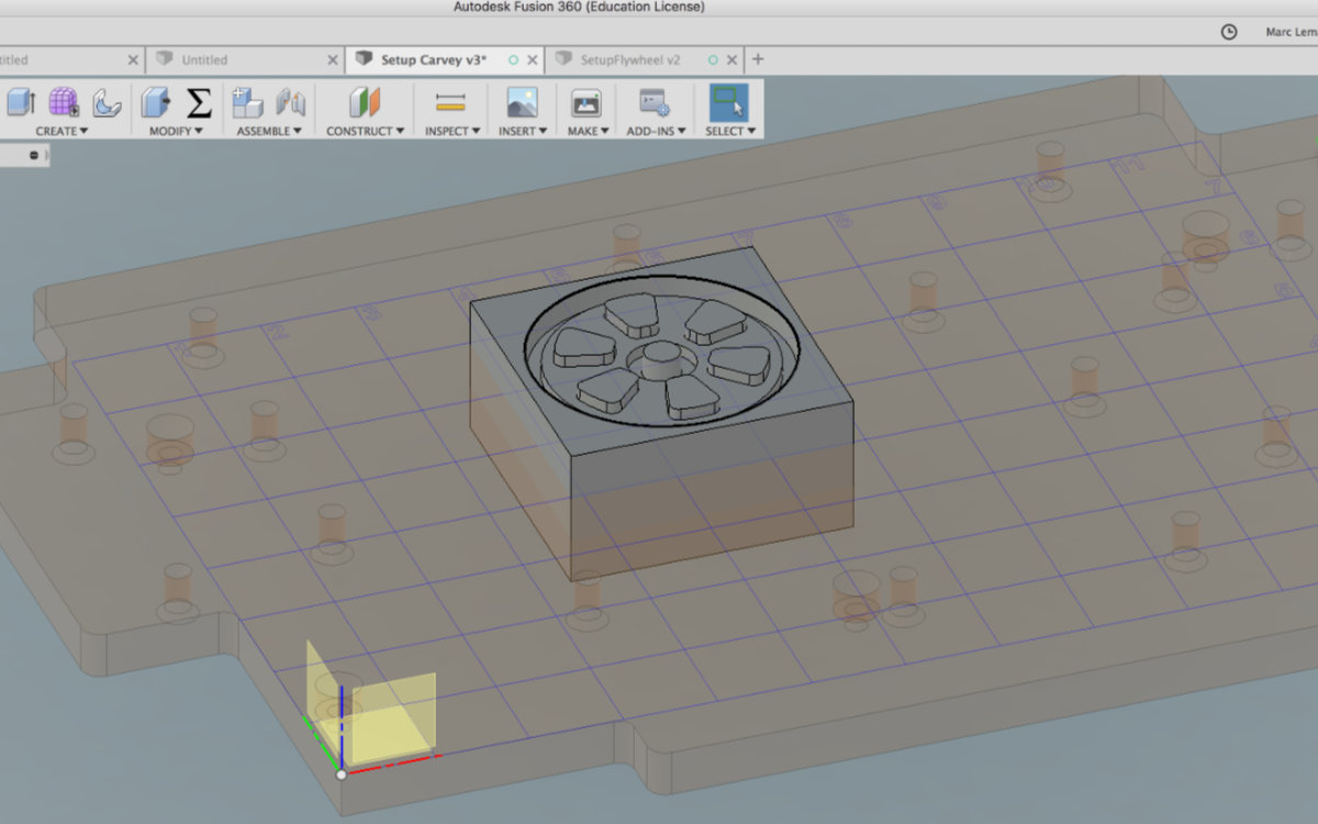
My project was ready to be milled at least for a couple of weeks. But the file was really prepared for the milling machine at échoFab. As I was at Alec's lab and the Carvey was available once my Input circuit was done, I tried my luck with carving my mold. But problems were so quick to pile up that in the end I came out of this session empty handed.
I came in the lab with a lot of much needed M5x50 bolts for the Carvey. The previous week, Alec told me that he needed longer bolts to make a more solid setup of the material. We gestimate what was needed and came up with M5x50. As he was explaining to me the machine worked, we realise that what we needed are at least M5x55 bolts for clamping down the square block that is also the origin detector.
The second problem that I encountered was that unknown to me, I had to place my mould on a wasteboard and configured the origin. On the Internet, I quickly found a Carvey wasteboard file that seemed, at first, to fit my needs and I started to get busy prepping my project.
I immediately encountered problems. Included with the file was a part which I couldn't get rid of. The surface of the wasteboard didn't correspond to the origin and, after carefully looking at the grid, I discovered that the said grid was not of equal distance. As the level of frustration mounted, I eventually found a nice tutorial on machinable wax at Autodesk University but this lesson was long (45 minutes) and I wanted results rapidly. I listened to thIe lessons and the author said that he had a wasteboard file available but I jumped too fast and missed the reference... I was no longer in a mood to learned but to get result, which of course is the least effective way to learn something. In the end, after many tries, I packed up my things and went home frustrated but having at least something done.
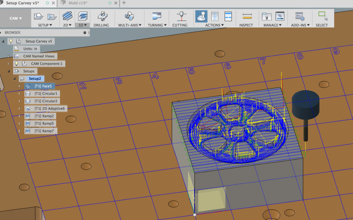
During my morning coffee, I listened to the lessons and deduced a few thing out of it. I downloaded and saved the wasteboard file and was happy to found that this one include only the board, no needless parts added. This file was also configure for the lower left corner at the origin. The surface correspond to the XY plane. The only issue was to move my mould, once imported, to the origin and then move it to the appropriate place.
Once there, I had to reconfigure all the operation. I had a few surprises, the most common one being the CAM Kernel dying on me for no reason.
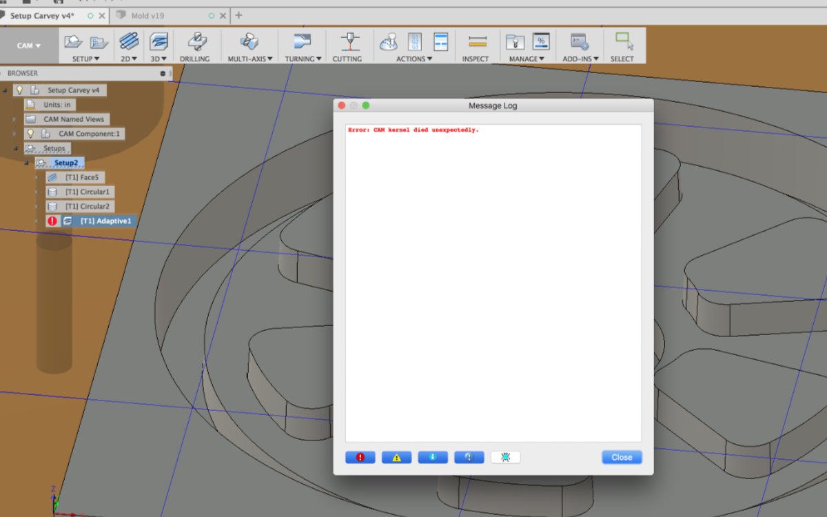
I went back and tried differents setups and came out with a complete program. As a side note, while almost identical, this new program has almost no errors but I got a strange behavior while doing ramping the inner surfaces that I haven't been able to fix. This one must ask around how I got this.
But wait, there a problem!
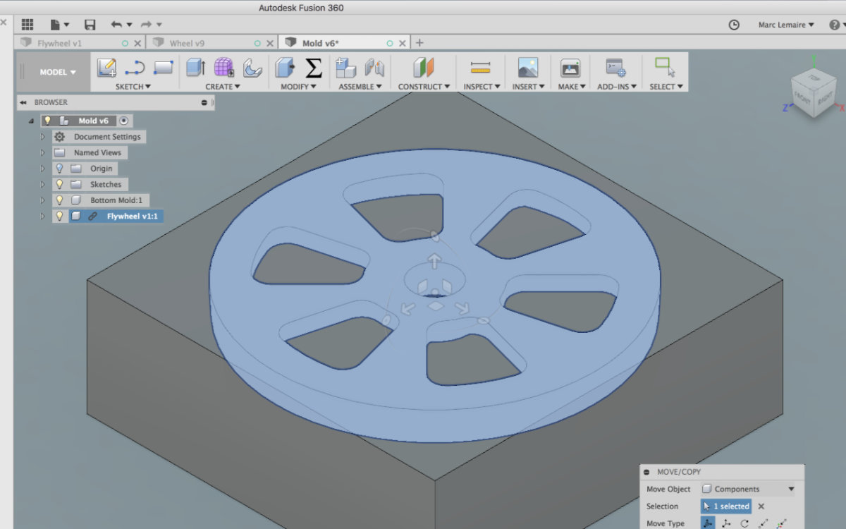
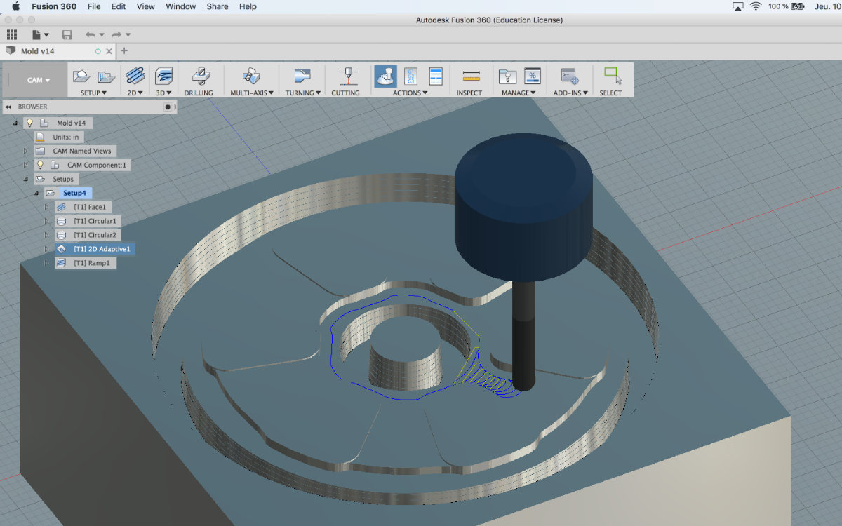
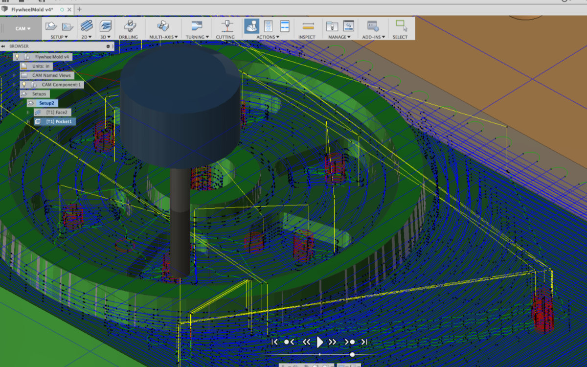
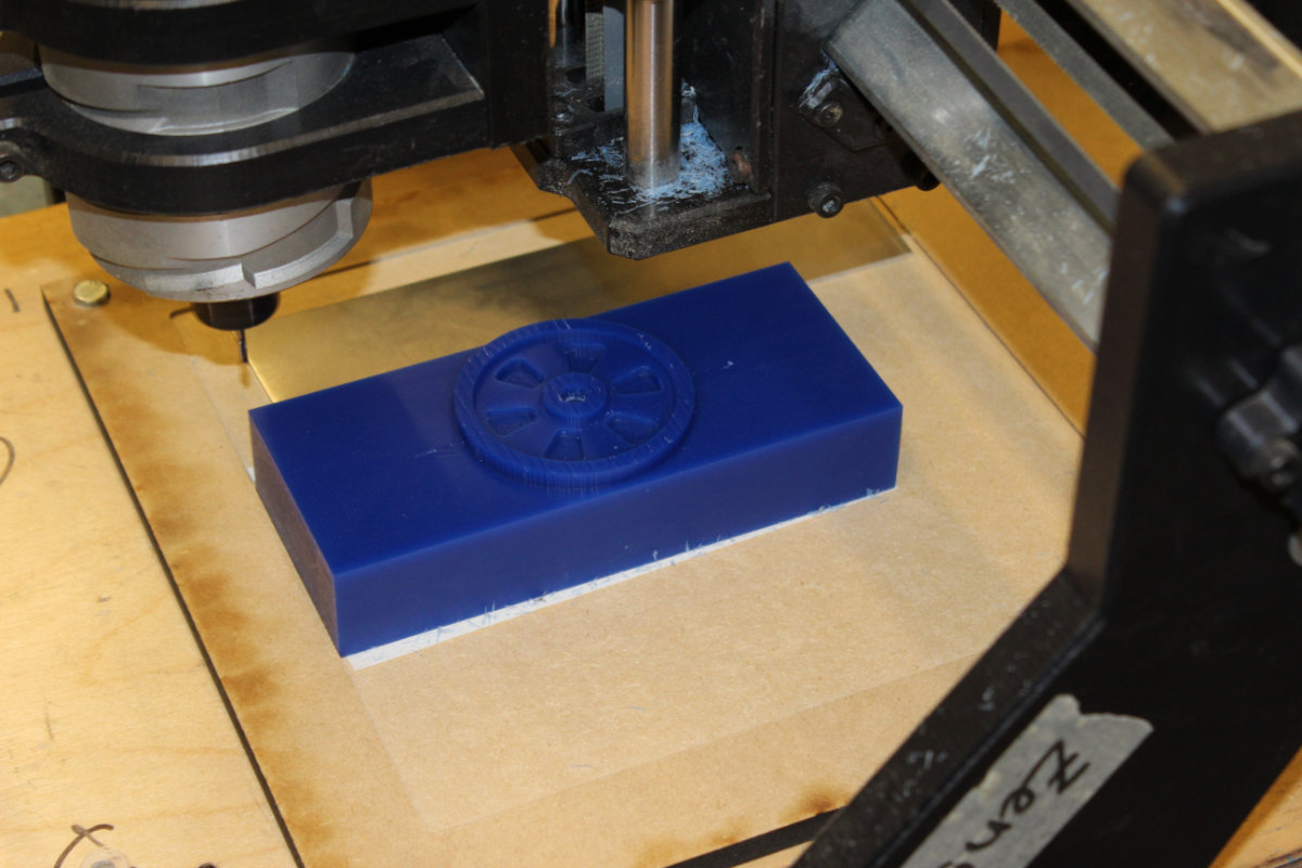
It was during observing the projects made by George and Alec that something hit me: I was making a negative while I must make a positive! I was so evident that it never occured to me until that moment! After working on this project, I realised that I must start again from scratch. But contrary to what I beleived, the making of this file went very well and I got no errors at all for the whole duration of the simulation.
The making
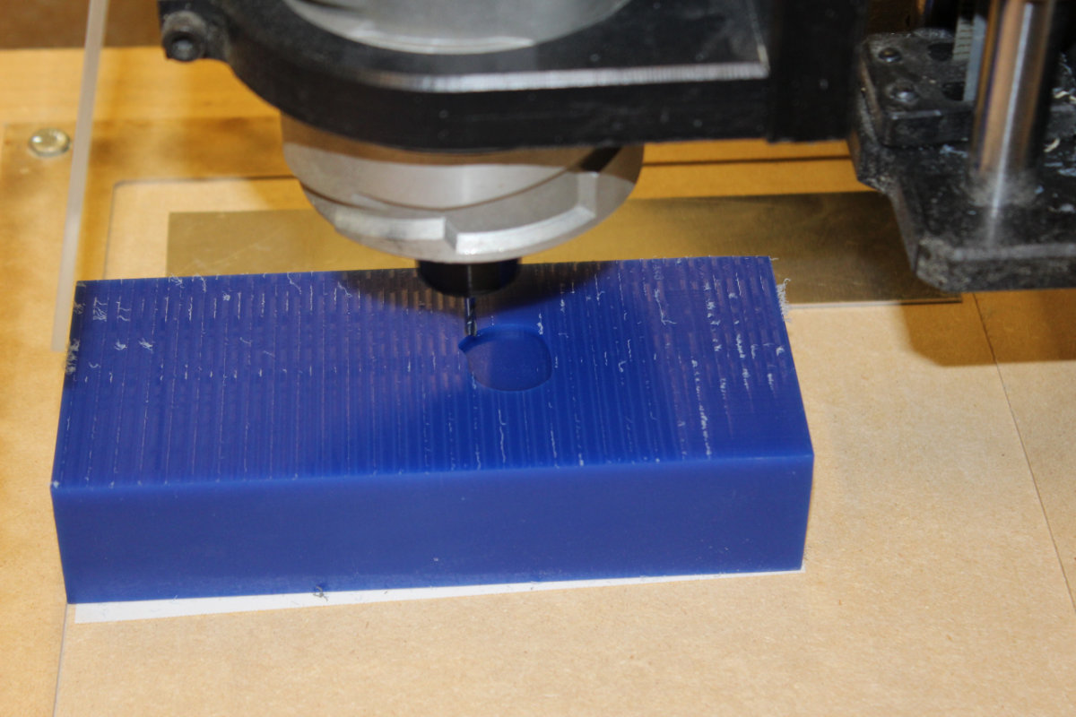
I had the opportunity to make the mold at the lab. Since my file was ready for the Carvey machine, I had to modify it to standard milling machine. I had to replace the form to the origin, modify the model point to the top surface and regenerate the toolpaths. Once this was done, I was ready for action.
I made my set-up, and this time I had to adjust the origin of the mill on the top surface of the machinable wax block. I eyeball the middle of the mill for the X and Y axis and was done with it. I started the machine but to my surprise, it went here and there and finally started "milling" over the top of the block. It's then that I modified the origin to the top the machinable wax; the file was still configured to the peculiarities of the Carvey.
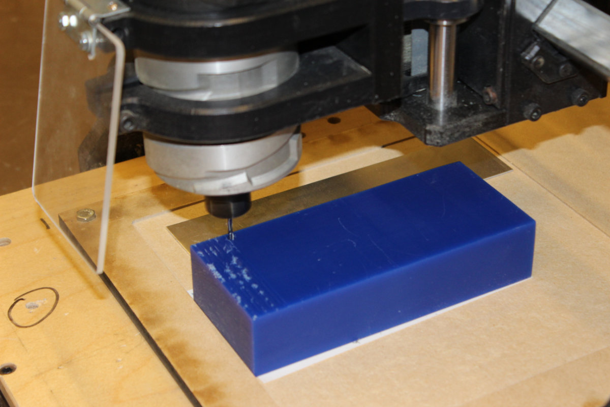
From then on, the machining went without any problems.
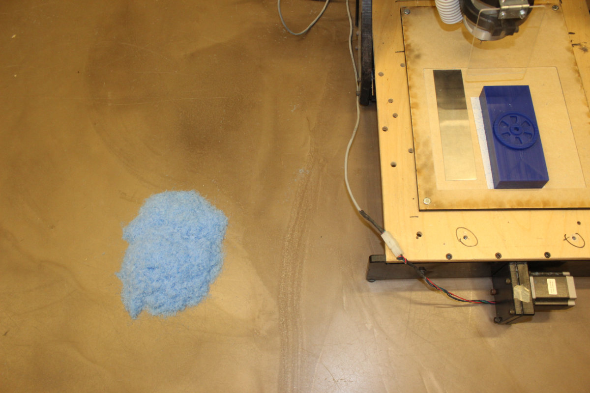
The importance of a clean floor
Before starting the milling, I had a very important chore to do: clean the floor. As this is machinable wax, the waste material is reusable: it's wax after all. Since the mill don't have a suction system, the waste was scattered all around the mill. Once my part was completed, I sweeped the floor to recuperate all the wax.
The molding process
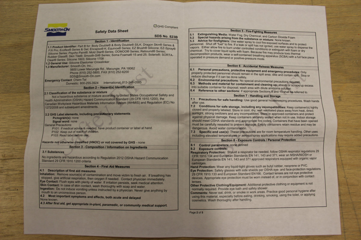
Molding is a chemical process that can be sometime toxic. You must always read the safety data sheet that it provided for your own protection. In my case, the product is no toxic at all. But you better have some gloves because this one product is really sticky.
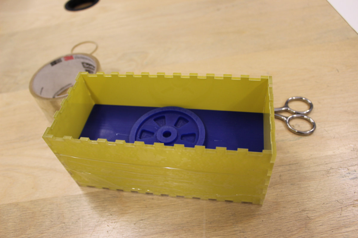
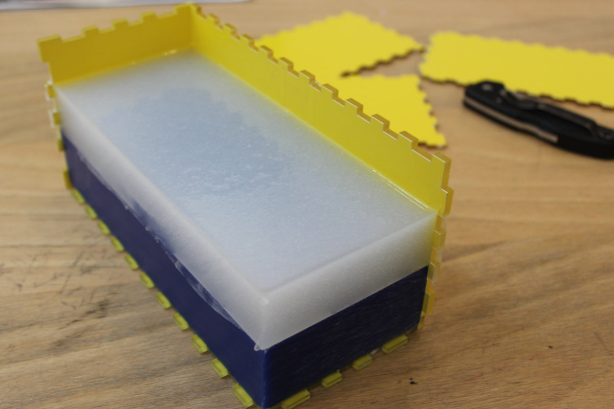
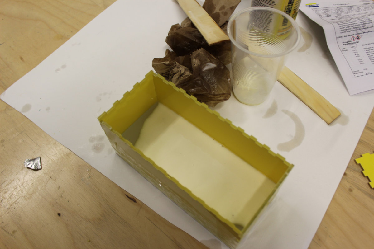
Now it's time to do the mold. I had to assemble the mold out of laser cut parts that was made to fit the dimensions of the machinable wax brick. I carefully taped all around the edges and the bottom so that no molding material will seeps out of it.
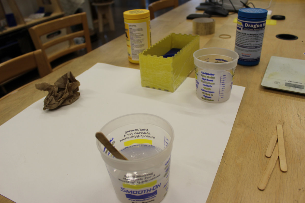
It was time to mix the silicone. I measured for 200ml at first for each parts but then scaled it down to 150ml for practical purposes. I was a long and boring process, and for this first time, wasn't entirely sure that I was doing it ok as I kept seeing bubles in the mixture.
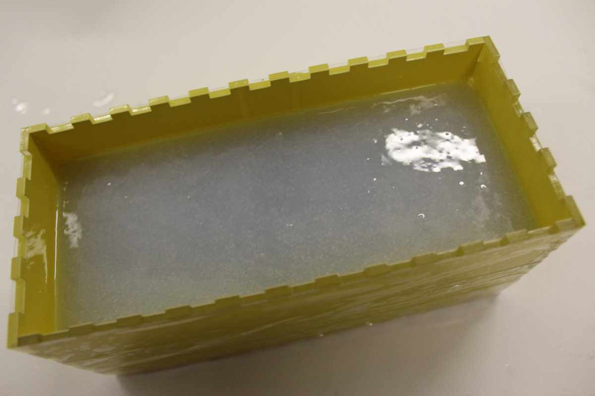
Eventually, it was time to pour the mixture into the mold. Following the instruction, I pour it as a thin filament into the mold.

All the 300ml silicone rubber was poured into the mold. It has to settle during the weekend and I hope that Monday morning, I will have a nice mold ready to be used.
All in all, a very positive experience and I'm glad having learned this process.
The molding
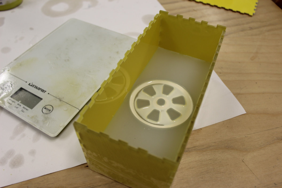
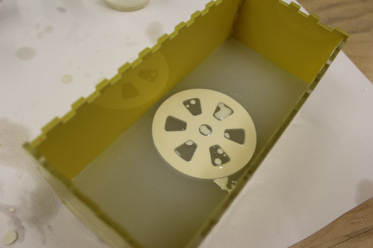
Next Monday morning I was ready for the next and last stage of this assignment. The first step was to unmold my silicon mold of the wax model. I was a little nervous when I first took a look inside: there were still many microscopic bubbles that were present as when I left and was afraid that this would influence the end results.
Those worries melted away when I released from the wax a perfect silicone mold. It is really impressive to see the amount of details that this silicone reproduces. I mean, it reproduced everything; the traces that the mill left were particularly remarkable.
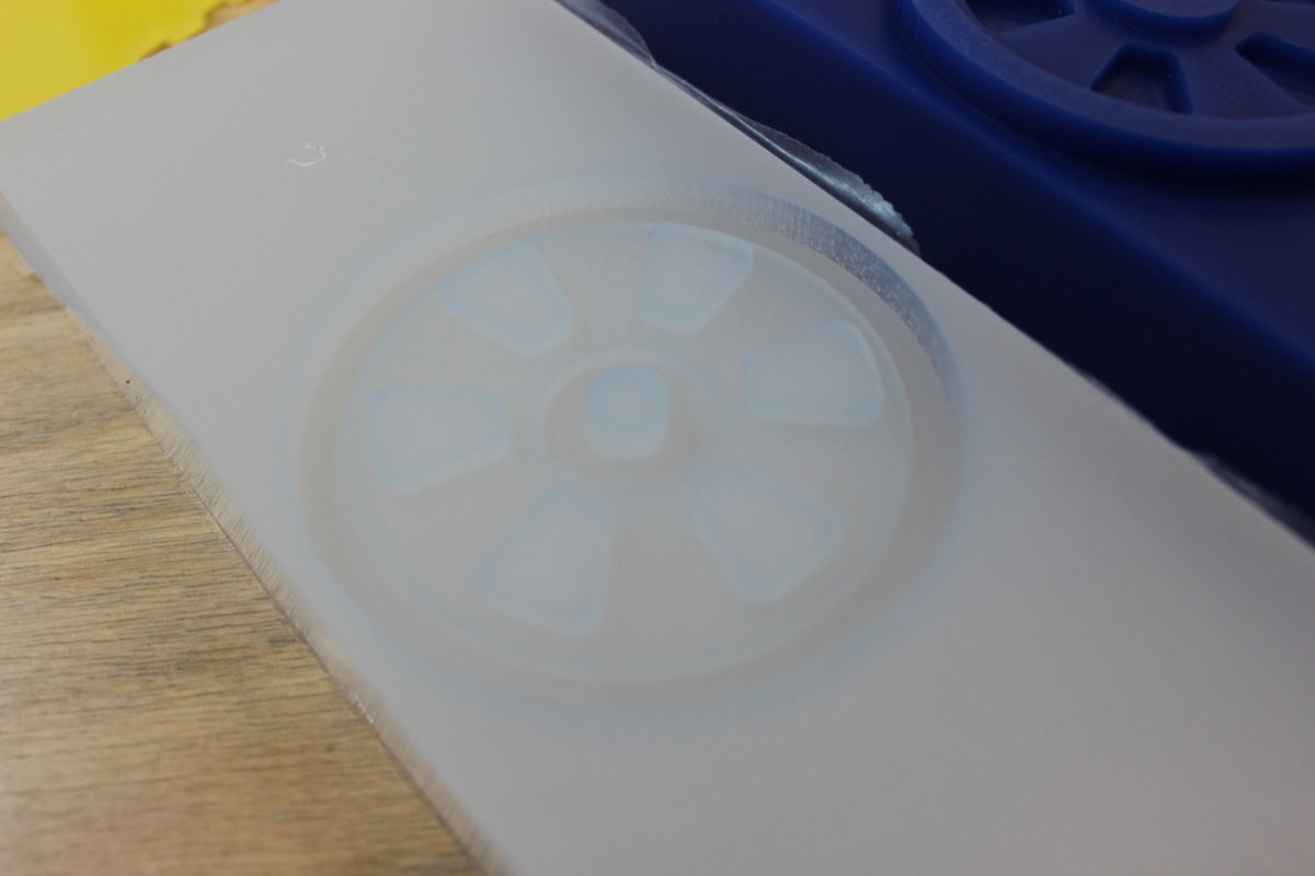
Those details are hard to see on photos because of the translucent material but they are really striking.
I only had to clean off the edges and put back the silicone mold in place of the machinable wax.
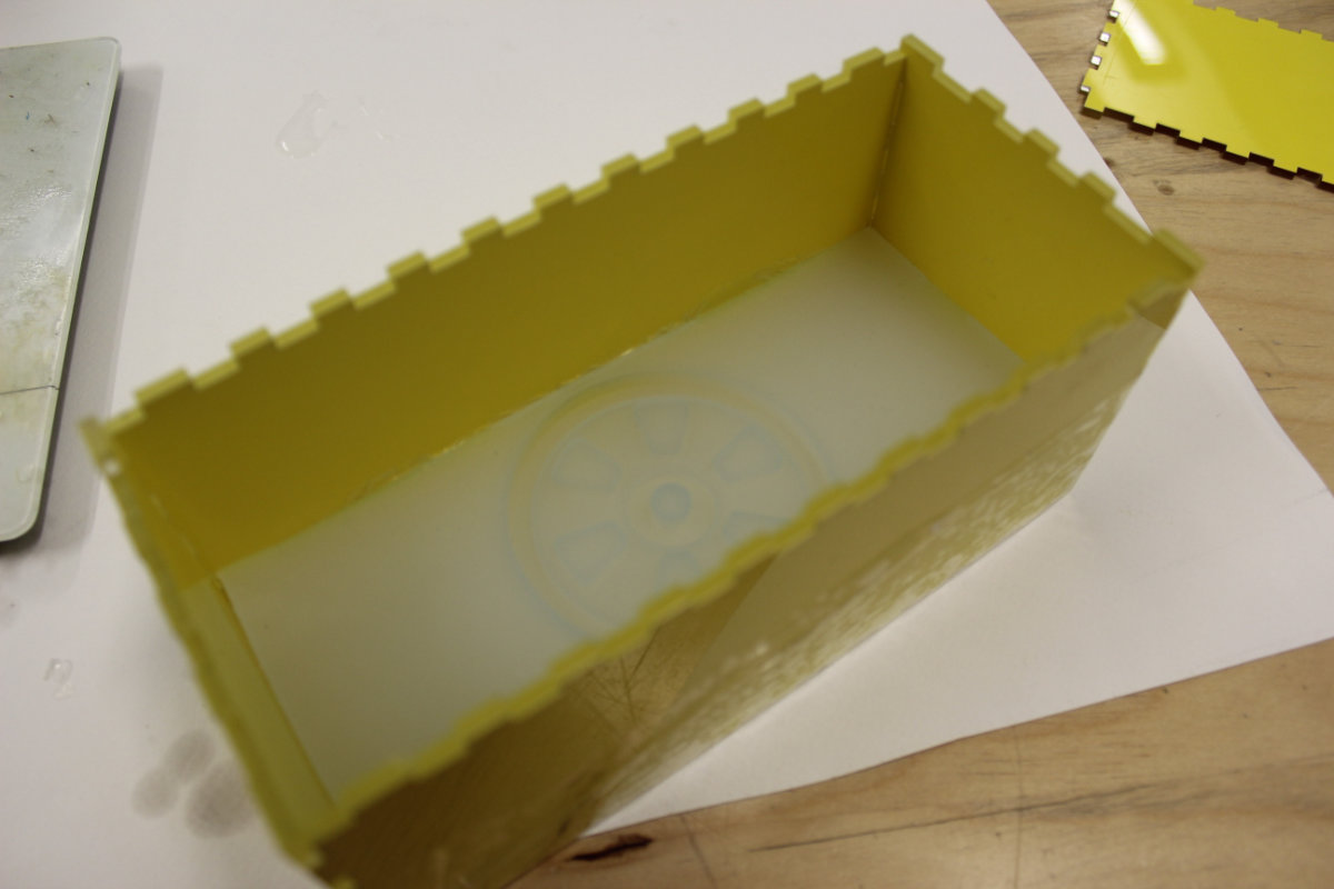
Molding the parts
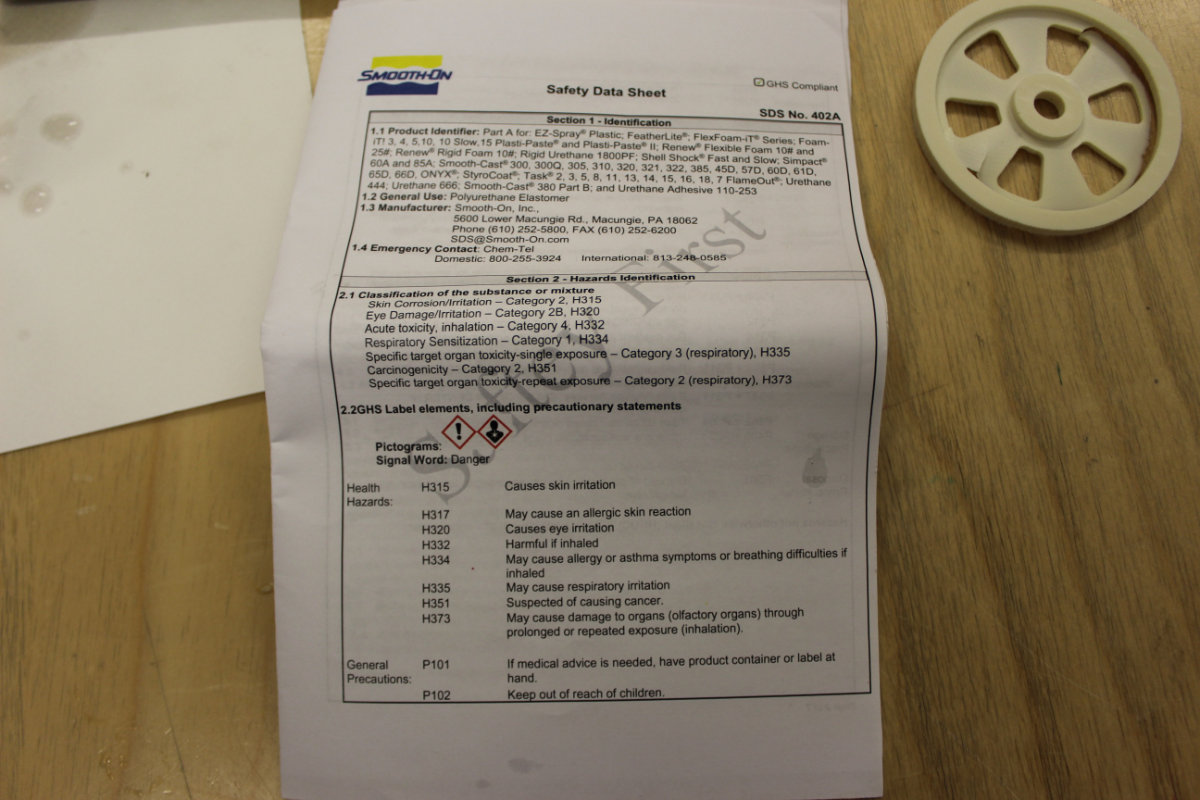
Now was the time to make the final part. But before going further, I needed to read the Safety Data Sheet. For this product, Liquid Plastic, I was warned that this product may cause skin irritation is inhaled. I was uneasy at first. But I determined that I was in a vast room and mixing small quantities of that stuff, and that if worst comes to worst (having an history with asthma), I have my breating mask, a real one, in my bag ready to be used. My deductions were right. That product has a not so strong smell but you feel a certain discomfort when the product is near your nose. If I had to mix a larger quantity, in a smaller venue, I would have put my mask. Be prepared in any case. And read the instructions before handling chemicals, it's safer that way. And wear gloves ! And glasses !
I used a balance to measure the quantities and used two disposables plastic cups to measure the chemicals before mixing. I had some spilling problems but those could have been avoided if I had access to some pipettes, or funnels, or both, both of these that I have in quantities in my dark room.
My first experience with mixing the chemicals ended up in the trash. But I had a laught. Having mixed in equal amounts the chemicals, I mixed them, and continued to do so, trying to dissolve the bubbles. When I noticed that the mixture was changing from transparent to white, I tried to pour the mixture into the mold but the mixture never went to the lip of the cup, it froze there, giving off heat from exothermic reaction. I laughted at my mishap but I learned about the time that I have before pouring. Good lesson.
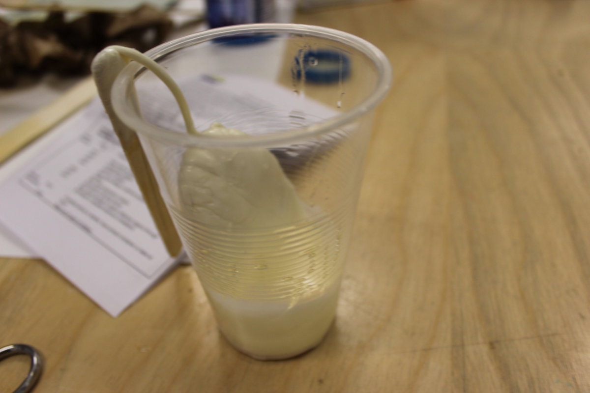
The second try was more successfull but I poured the whole cup and there was too much material. By weight, I measured 20g each, for a total of 40g.
Third time the charm
By now I had figured out the right quantity and knew about my mixing time. I mixed a 12g of both mixture and pour those in a single cup.
I was sure that this one was good that I waited a long while just to be safe that the plastic had setted and I would not bend the part during the unmolding.
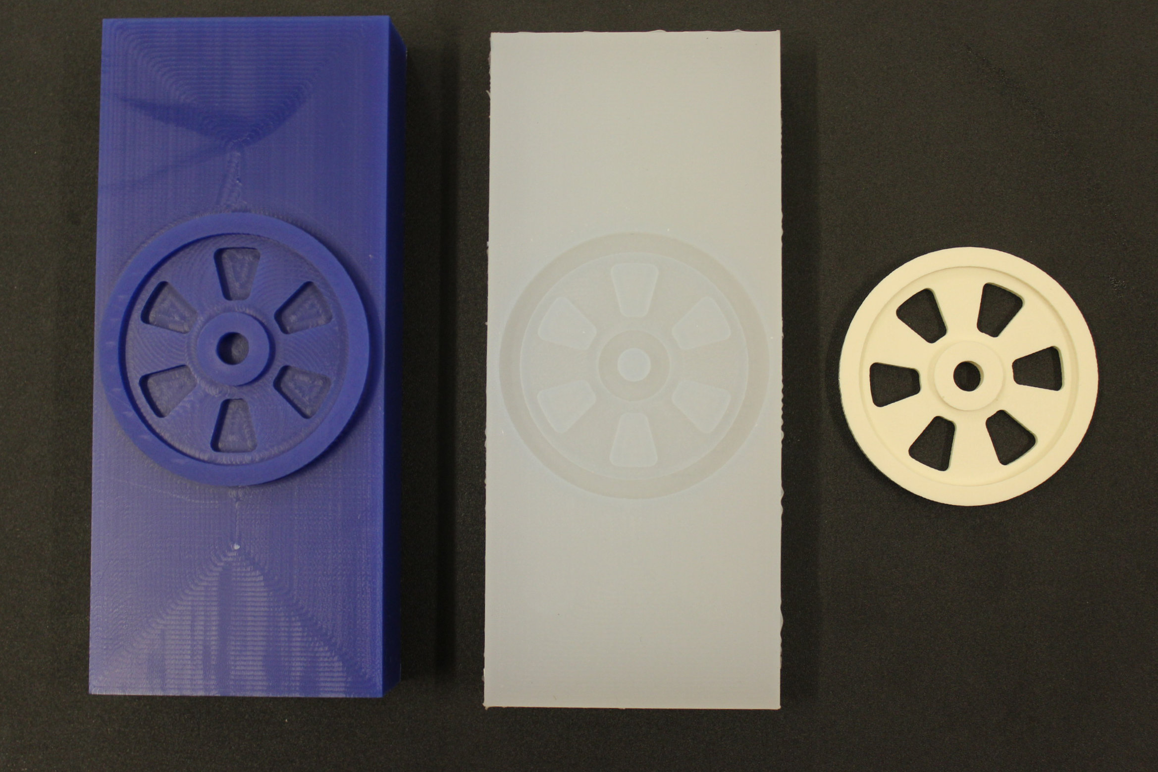
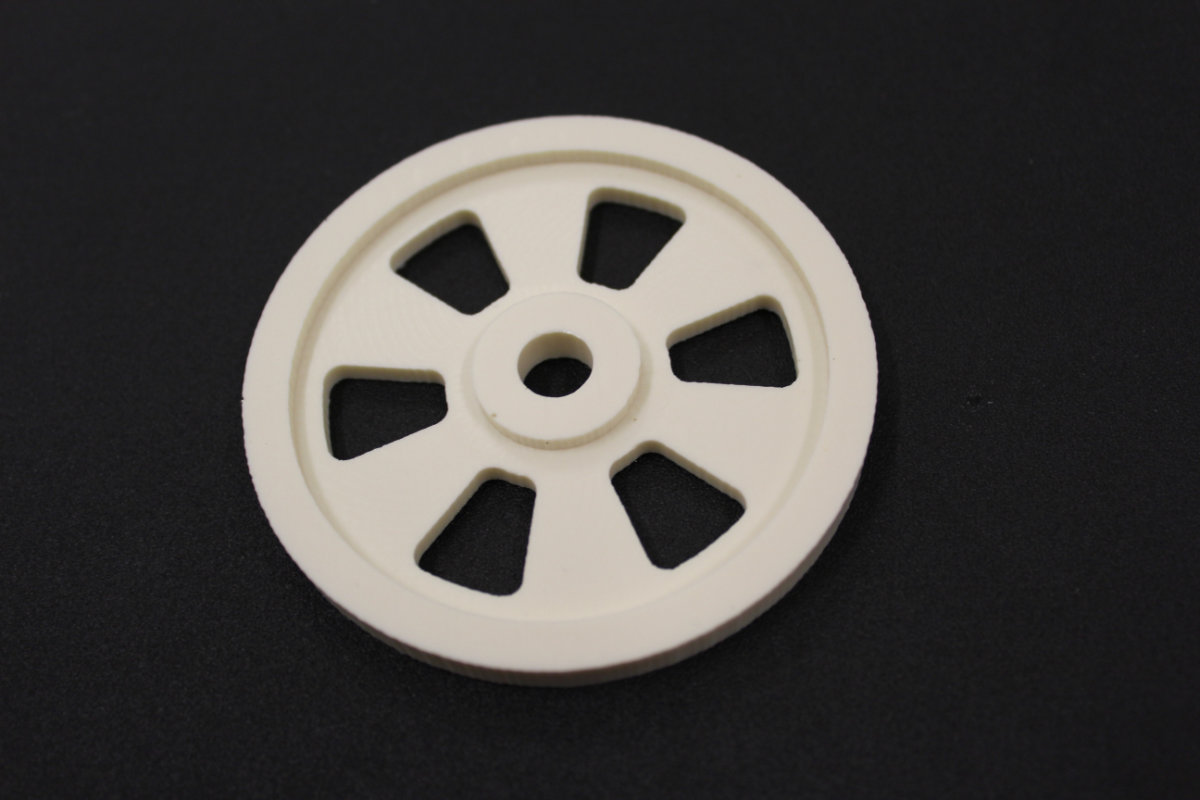
As you can see, the unmolding went whitout any problem. Always a concern, I only had a tiny air bubble on the surface of my part.
Closing thought
I'm glad that I did this thing. This is my first mold and not my last: as a model railroader, this skill is highly useful. I will never forget the lessons learned here. This assignment has an emphasis on making something and quality control was not part of the equation. Next time, I must be prepared and take good care of the surface finish, as this make or break a model, as all details are duly reproduced with silicone. Althought not seen on the pictures, I softly sanded the top surface of the wheel on the machinable wax: on the finished part, you see those almost invisible marks. As I previously noted, you also see the toolpaths of the mill even more clearly. This execice was an introductory one, but next time, I will have to carefully remove all those remnants of the fabrication process, like any patternmaker worth his or her salt. And this takes time and patience.
