Machine Design
Week 16
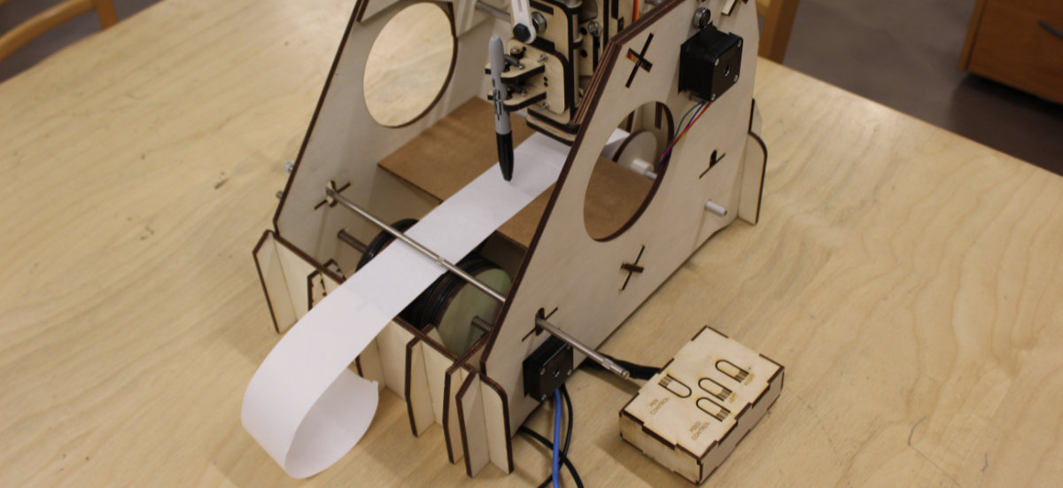
While waiting for the nodes, I'm concentrating on the output assignment week that I haven't completed yet. I realised at the end of the day that this assignment can be useful for our Machine Design week.
A simple stepper motor program?
I started to work on the stepper motor assignment because I was waiting for the Gestalt Nodes order to arrived with the idea that if I get this assignment done, that experience and learning will be put to good use to program the nodes.
The Output Board Experience
The initial board was ready and I only have to add the components. Those were done quickly and I had a nice finished board in no time. I thought that if the programming was as quick as the soldering, I will have an assignmnent done today! Guess what? Yay, I learn quite a few new things but I was never able to activate the motor.
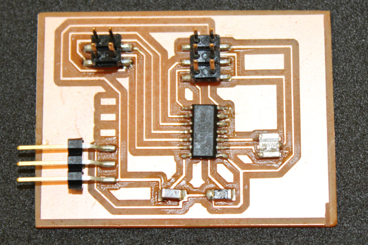
I got myself reacquainted with the board by reassembling the stepper motor with the Arduino board. Once done, I tackle the challenge of making the connections between a FabISP and the board. Since no smoke came out of the chip, I was ready to push the code to the board.
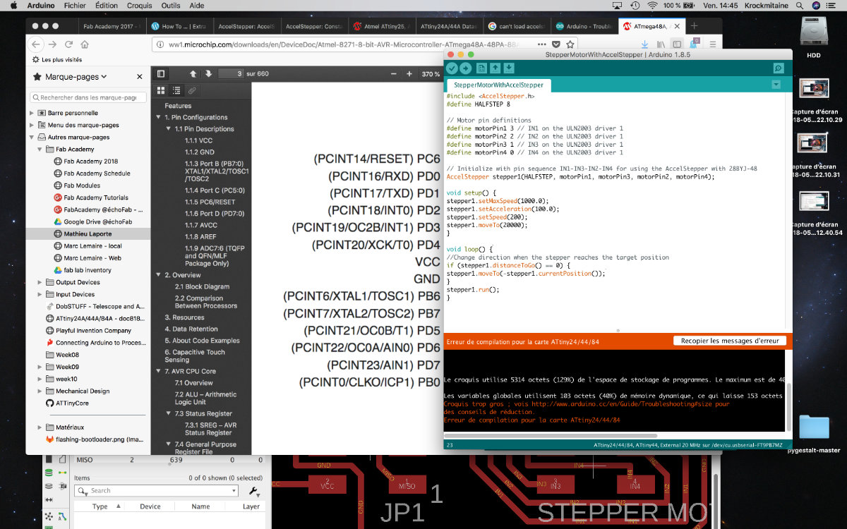
The original code that I use is simple, see the link. This sketch uses the Stepper.h library to control the stepper motor. From the original sketch, I had to translate the output pins controlling the motor (8, 9, 10, 11) from the Arduino board to the ATtiny boards (10, 11, 12, 13). Those pins don't correspond but they are easy to translate from the ATtiny24/44/84 pinout diagram. But that translation failed to activate the motor. Try as I might, I never moved the motor nor activate the LEDs from the driver.
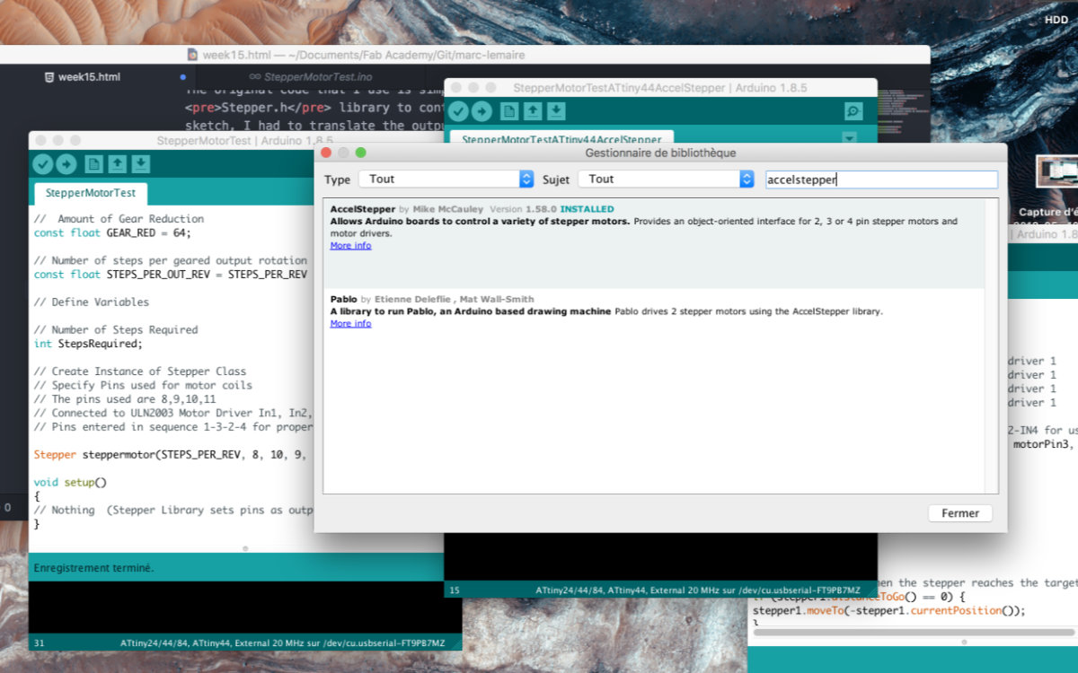
Trying to find a solution, my instructor recommended me to change the Stepper.h to the AccelStepper.h library. I installed the AccelStepper library using the Library managment tool included in Arduino: Sketch > Include a Library > Manage Library. On the search box, I type in AccelStepper, clicked the Install button and was done.
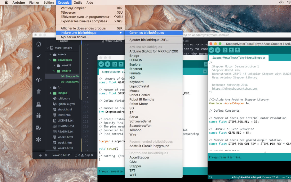
Once done I made the appropriate sketch and pushed it to the ATtiny. But it never went to it's intended destination. I received the message the the sketch uses too much space: 5314 bytes, more than the memory capacity of the ATtiny44 which is 4096 bytes. I have no other recourse than to redo the board with a more adapted microcontroler...
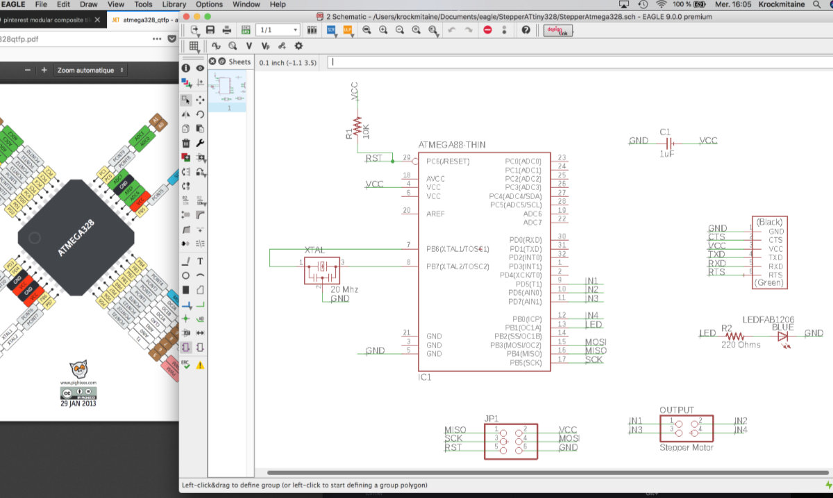
The ATmega328
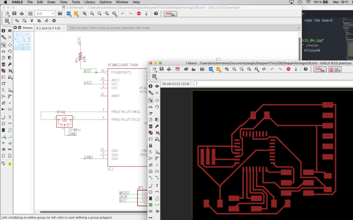
So back to the drawing board, this time with the ATmega328 instead of the ATtiny44. I read quickly the datasheet and made a quick schematic in Eagle, hoping that I wasn't doing any mistakes. I made a revision with my instructor, telling about the design decision that I made related to this chip. He gave me the green light, having found nothing to worry about, and I went to the milling machine.
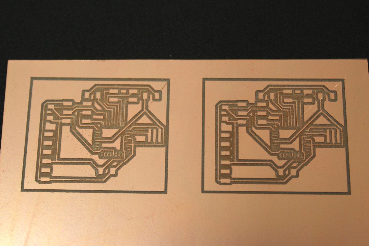
The output was done and I had a nice board. But the question remains: will I be able to solder all those tiny pads? I think I can do it but this will test my soldering skills to a new level. In any case, I made two circuits just in case something goes wrong.
That insurance policy paid off as I made a mistake on the first board and burned out a a pad from the ATmega328. But it was a good lesson that was applied to the second plate and the solder was pretty clean. And I never made use of the wick. That tool is not for me, but I used the pump and it saved me from a few closed calls. Once the chip was soldered, the rest was easy to do and I came with a very neat circuit board. I must add that I had only two chances with the ATmega328 as I used the last one that the lab had.
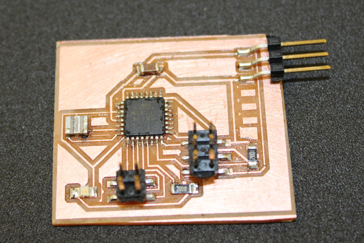
For once, I felt a sense of accomplishment when the board was completed, cleanly soldering all those tiny traces. A sense that I haven't felt since the start of Fab Academy. But I know that this accomplishment can be an empty victory if the board isn't a functionnal one.
Unfortunately, it is.
Last comments concerning this frustrating episode
So, I worked like a madman and at the finish line, I came up empty handed. First the Gestald Node board that was dead, second the ATtiny44 with a too small memory and third, the ATmega328 that didn't connect. But, I learned quite a lot on all these components: I know how to configure a Gestalt Node, the limited memory capacity of the ATtiny44 and a new expertise on ATmega328. Plus, a new level of soldering expertise.
Time to move on
But I had no time to waste pondering about my less than successfull week as we had a machine to built and make it functionnal.
Since the custom boards were no longer an option, the Gestalt Nodes haven't yet arrived, it was obvious that we had to come up with a solution fast for our machine otherwise we would not make it for the deadline. I went to the more familiar Arduino territory. Alec had been investigating it and he sended some tutorial about configuring an Arduino board with stepper motors. What's more, he came up with the EasyDrivers modules at the right time. I started out doing the tutorials on the Easy Drivers Exemples page and familiarized myself with the steppers, basic with one motor setup followed by two motors setup with homing switch. Those tutorial went with no problems as they are really well made. I made a first setup with one motor by following the How to set the HOME position of a Stepper at Startup! at the Brainy Bits web page. Once tested, I added the connection for the Servo Motor controlling the effector that George made.
So I was now with two Arduino boards with plenty of pins. I decided to go overboard and integrate all the pins into one board and one sketch. But this plan didn't go as smoothly as I tought. Integrating was starting to get too much of my time and Alec reminded me gently to eliminate all layers of complexity. As it was getting late, I was tired and took his advice. I dismantle all that I've done so far and went back to my initial, and working, two boards setup.
Integrating the interface
After all this exhausting work, there still remain the task of integrating all those wires into a neat box designed by George. While I left at the end of a long day, Alec and George stayed a while and finished the machine and made tests and it was functionning as intended.
That task would normally be an easy one for me as I've done this many times over. But I was tired and exhausted. During the whole integration process, I was always concerned not to do any damage to the program or the machine.
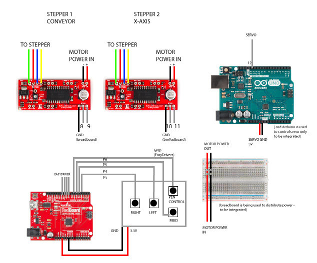
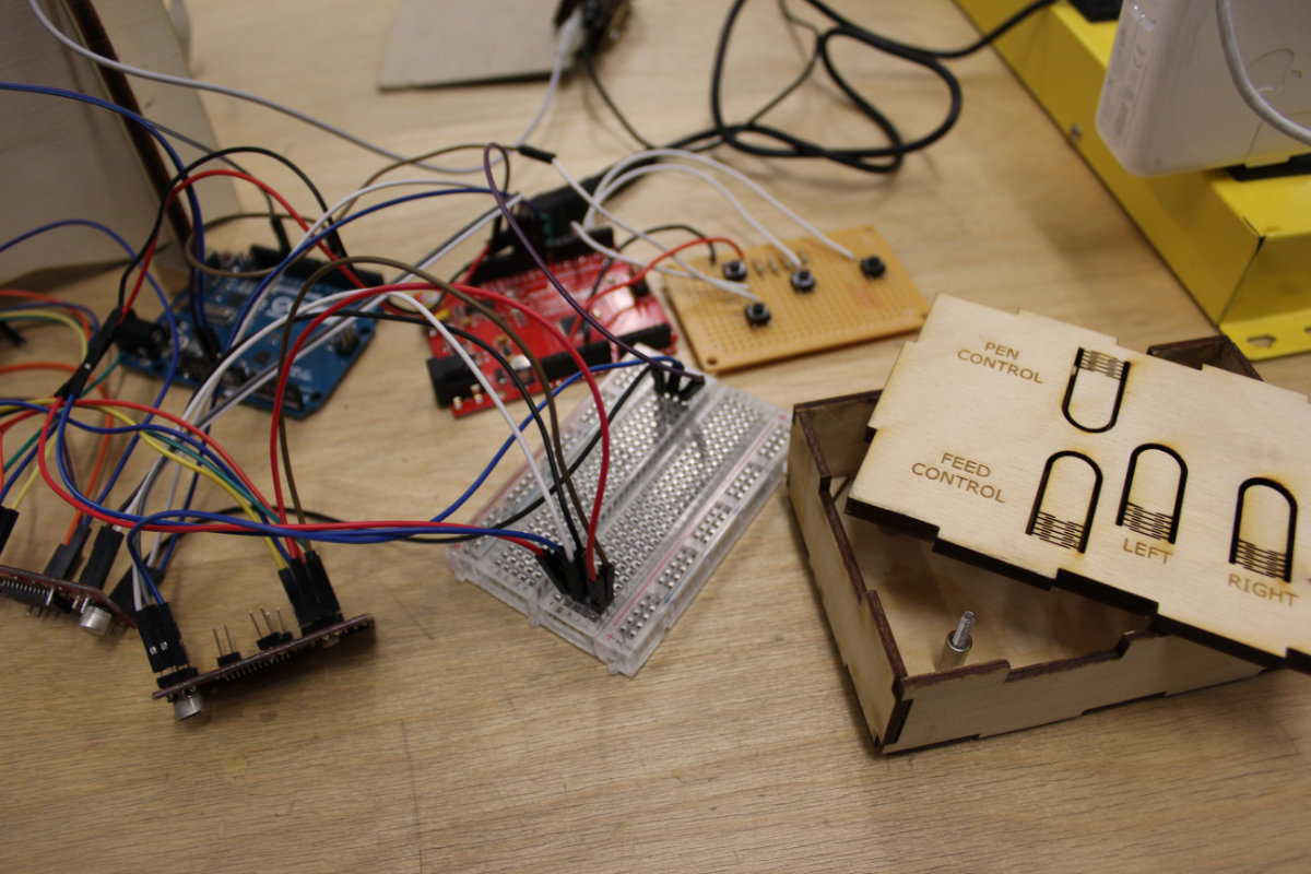
I started by getting myself acquainted with the setup and expecially the box. I wasn't even sure that everything would fit inside. I had to put the board with the buttons in the box and level it so the buttons on the cover would activate the buttons. I eventually found an box full of nuts a picked up 8 M3 nuts. I measured an ideal height for the board (5mm) with a caliper and locked the lower nuts with glue. I put the board and put 4 nuts on top so vibrations don't get the board out of alignment. Once done, I delicately put the two EasyDriver on both sides of the board and made sure that all would fit with the cover in place. It did. So I removed the cover, then the board and the drivers. I then enlarge the hole to make place for all the connecting wires that I will have to fit inside.
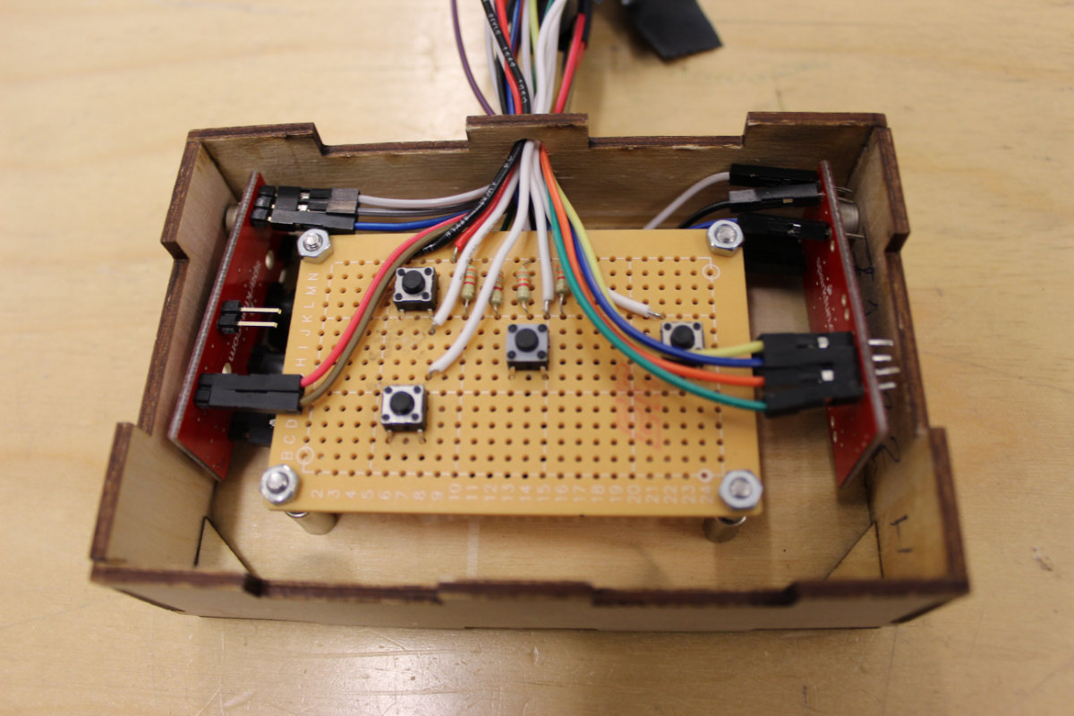
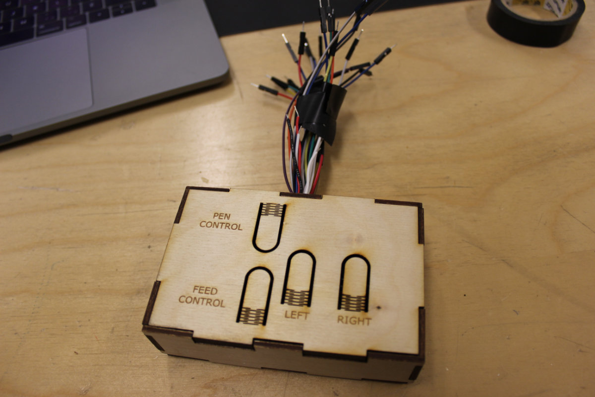
I would really worry about using such an enclosure as the drivers generates lots of heat, and we're using 5 volts to feed the motor. For normal operation, this box is in need for ventilation holes to dissipates the heat. But since this is a prototype, it's not a concern and it will do a nice job with it's expected operating parameters.
Once this was done, it was time to solder extention wires to the shortest wires so I can connect them to the Arduino.
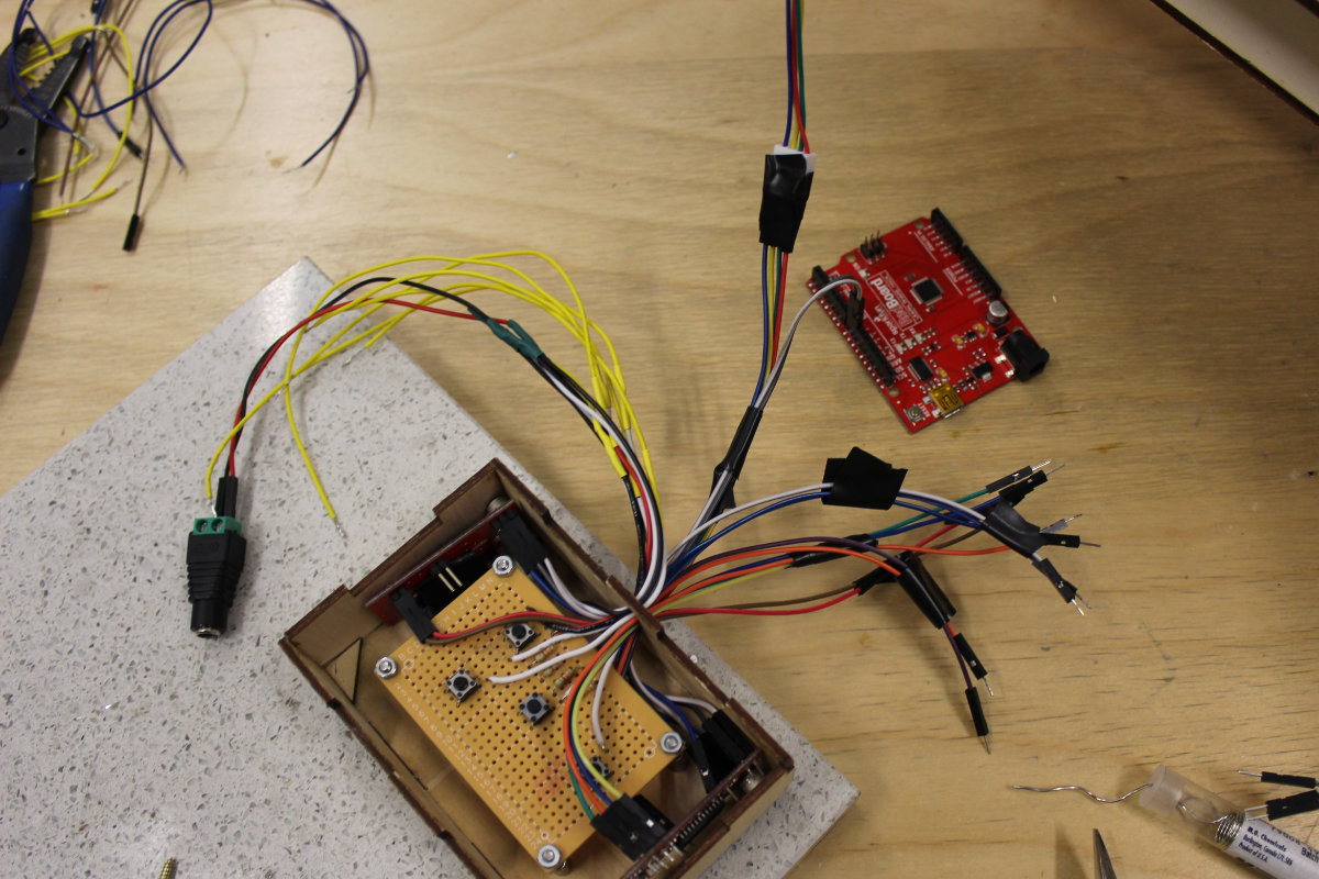
This slow process of soldering and connecting the delicate wires came to an end and I had to connect my box to the machine. Not having appropriate wiring harnesses, I used black electrical wires instead. It's not my first choice but I had to make do with what I had available to complete my task. I made a quick test to ensure that everything was ok but I was really dissapointed that some wires were mismatched. At least, no smoke! But I was obliged to leave the lab and could't locate the problem.
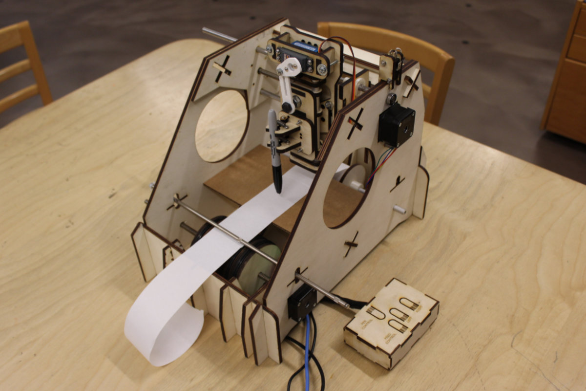
Video 2: The first time the machine was powered with all the motors
Video 3: Programming the machine with the pen marker.
Tasks that I've done
For this week's assignment, I've done the following:
- Design output board;
- Design the stepper motor sketch;
- Design a board with ATmega328;
- Making the electronics;
- Making the integration;
- Desing and cutting of the GAM platter
- Taking pictures of the team;
- Making and documenting the group's project page.
