Rocker Box
Before realising the final project, I must first master how to draw with parametric design software, namely Fusion 360. I had previous experience with CAD design. Compared to today's offering, it was really primitive as we had to design every part and then make the final assembly plan. Fusion 360 on my old Mac is way more powerful than the big station that I used back then.
First design of the base
Fusion 360
It's been decades since I touched a real CAD program and this one is a complete change of what I'm used to: instead of drawing the traditional way, like the drafting table, I now must learn how to use sketch. I immediately saw the big advantage of parametric design. In the Highe book, the author includes an Excel sheet for different telescope diameter. Instead of going back to consult the Excel sheets and redo the plans, I draw once and modify the dimensions to suits personnal needs.
At first I was having some difficulty working with Fusion 360, namely with the concepts of sketches, but I went back to Lars Christensen's absolute beginners tutorials and re-learned the lesson that a sketch must start on a surface or a plane.
First attempts at the Rocker Box
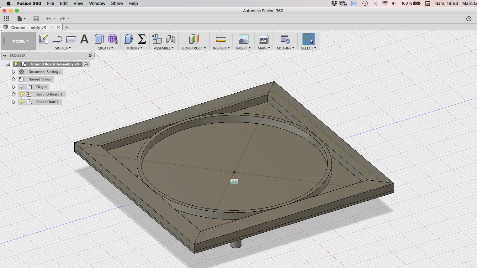
My first attempt at designing the Ground Board was the same as the triangular base. I followed the author's instruction with using a ¼" sheet of plywood and some strips of 1¾" x ¾" glued to the sides with a central hoop. I made the design and then started to think when I looked at the result.
Then it hit me. The author has an approach to telescope building that don't apply to this project. His DIY approach is very good when using traditionnal tools but within a FabLab, more options are available. I came to the conclusion that I needed to redo what I've done but with a digital machining mindset.
First, the central hoop. It's a specialized item that need special cutting and assembly. Besides, I need to locate a hardware store that is ready to order this item. Ordering from the United States is possible but simply too expensive. Why not replaced this with a strip of living hinge made from a flat piece of plywood? It's a possibility with a laser cutter. Then I looked at the strips and started to wonder why not try another solution, specifically, why not simply mill a ¾" plywood with some pocket to shed some weight off the assembly? From thence, mill a bottom and top panels and glue them together for strenght and lightness. As a side benefit, I simplify the part assembly from seven parts to two milled panels that accomplish the same task!
Making progress
So I analysed the parts and came up with an elegant solution: take a ¾" thick plywood and machine everything in one block: no hoops, no side strips, no complex sandwich construction.
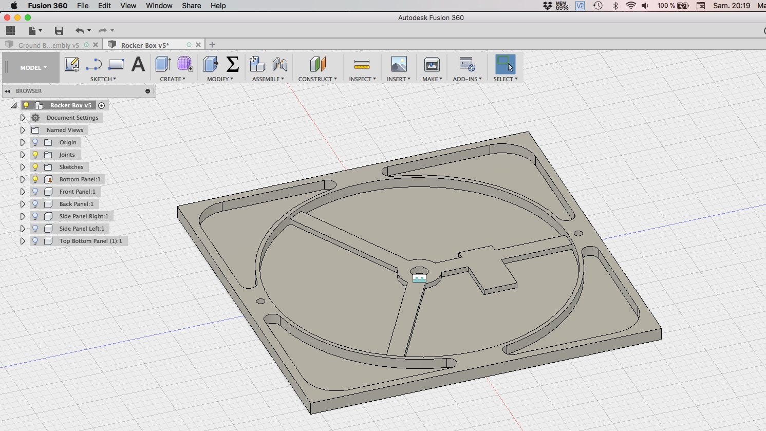
From the ¾" plywood I milled out almost to the bottom, leaving a ⅛" thickness for aesthetics purposes. The ribbing are for the central pivot point and the location of the motorized system will be over the rectangular area. This is a first design and already I'm thinking about adding another rib to equalize the forces and distribute the weight more evenly. Also, I need more information about the end mill of the machine to optimise the profile of the interior pockets. The two holes are for pegs that will be used to center the bottom to the top panel of the rocker box when I glue these parts together.
Design of the Globoid Gear
Following the explanation of the previous chapter, it's now time to describe the process of making the Globoid Worm Gear that goes on top of the Globoid Gear located on the Ground Board.
As design goes, making a globoid gear would be a quite complex endeavor by itself and we're not even talking about making that said gear, which price would be prohibitive with subtractive fabrication (machining) but cost next to nothing with additive manufacturing (3D printing). Since I have a tutorial on hand, the desing of it is relatively really easy to make.
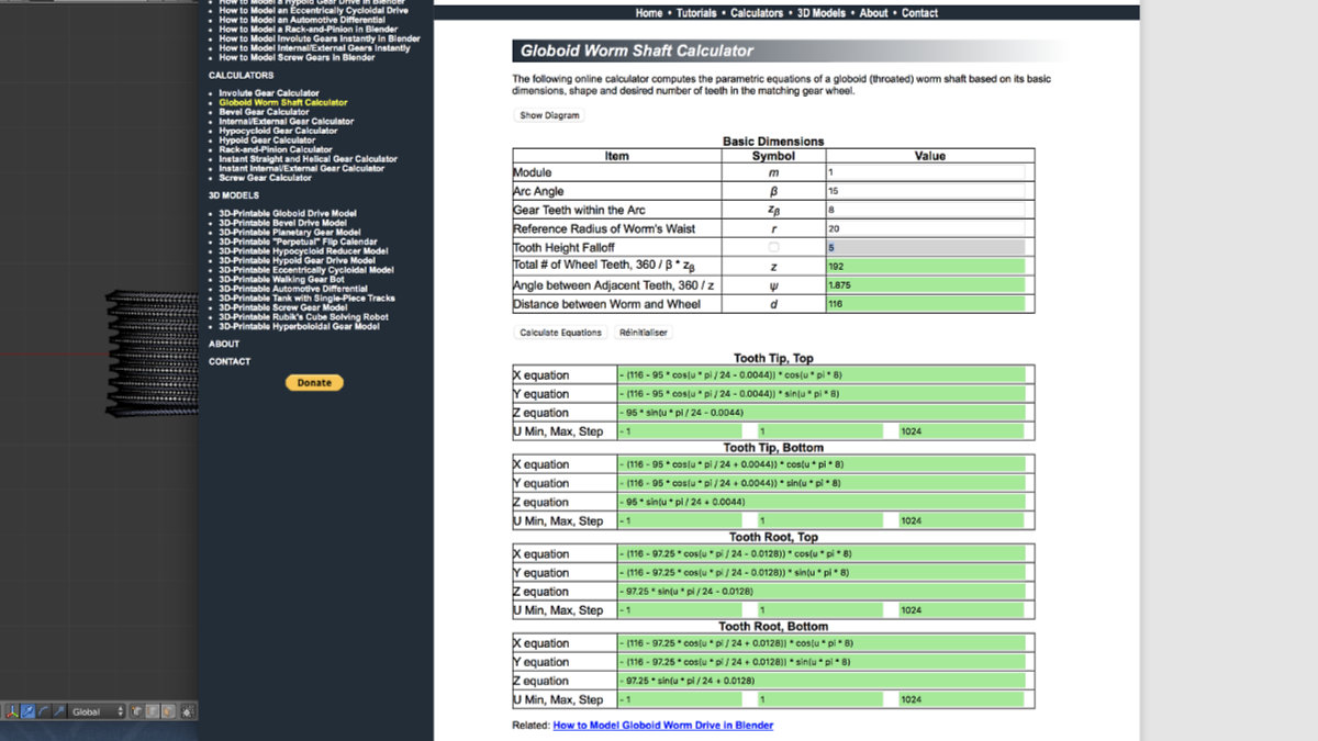
The first time, I followed the online tutorial for a test design and try to understand the (puzzling to me) design process: in technical school, you design with the interaxial distance and gear ratio and from this, design your system. Not so with this one: you have to put some dimensions and the rest is automatically computed. The most difficult task was to tweek the Reference Radius of Worm's Waist to my need, which are 6" (the inside hole diameter of the Ground board, about 150mm). As this is an automatic calculator, you can't put a number on the Distance between Worm and Wheel (which is the interaxial distance between the worm and gear). This is the most useful number when designing a gear train but had to work my way through with the module, the Arc angle, the Gear teeth whithin the Arc parameters to obtain my dimension: you have to really understand the tutorial to make a viable design.
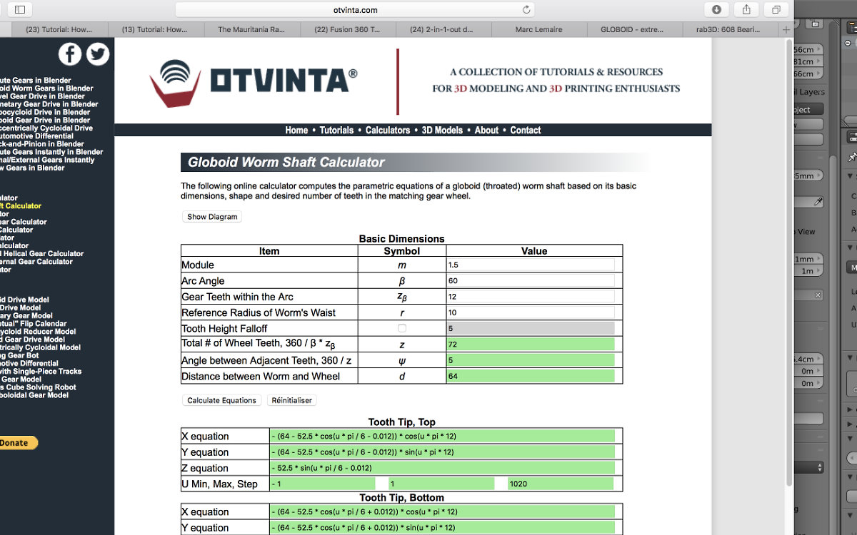
Eventually, I settle with a design of 54mm for the radius of the gear. To get to this dimension, I chose a module of 1.5, an Arc Angle of 60°, a Gear Teeth Within the Arc of 12 and the Reference Radius of Worm's Waist of 10mm. I then pressed Calculate Equation and I was given the proper dimensions for my design.
I followed the instructions given in the video tutorial and completed the globoid gear set. But the question remains: will it respect the dimensions that were given in Blender?
Making the gear
This tutorial is for Blender. Althought Blender is a 3D software package, it's not being developped as a 3D parametric CAD software. That being said, Blender can easily be configured to metric (or any other) dimensions. But will the mesh repect the dimensions? Let's see.
Configuring Blender for metric dimensions
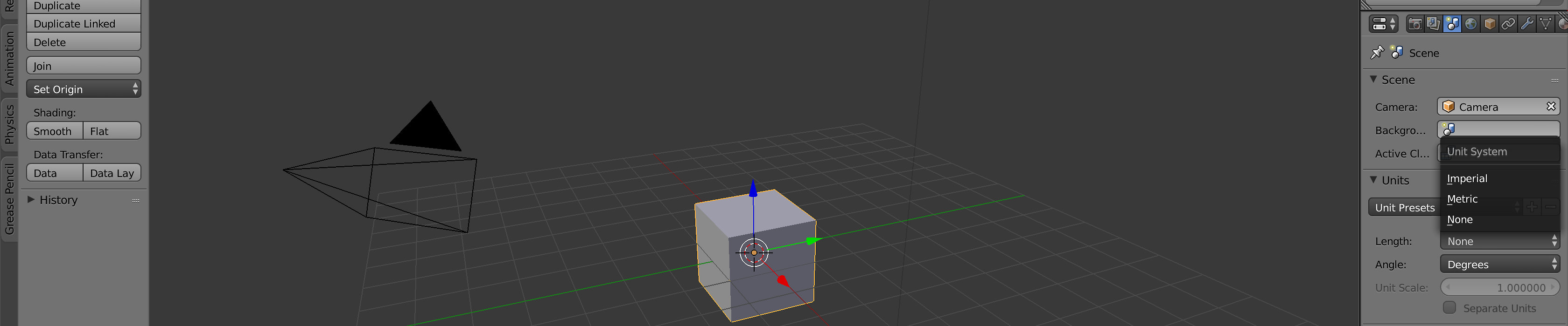
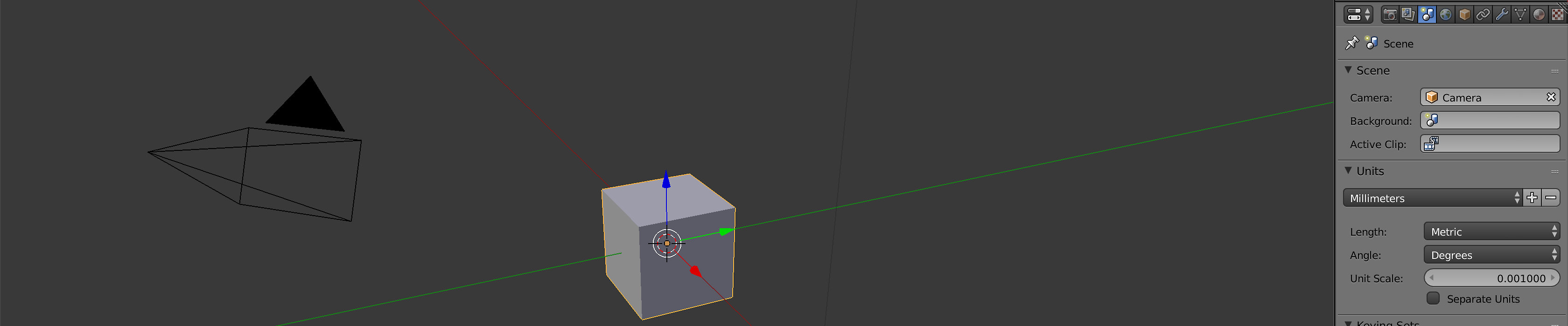
We have to set Blender to metric dimensions. Open Blender, go to the Properties tab (normally on your right) and press the Scene tab. Look for the Units section. Change the Unit presets to suit your needs, in our case millimeters, and you're done.
Danger Will Robinson: It's very important to configure Blender to a measurement system if you want to have a usable design in Fusion 360. Otherwise, you'll have problems and wonder what the ??? is going on. For exemple, if you have out-of-scale measurement by orders of magnitude and/or you can't edit your part in Fusion (when you do a cut, you see the inside of the part) the culprit will be the lack of a measurement system.
From this point, I simply follow the tutorial and copy/paste the formulas into Blender.
Making the print
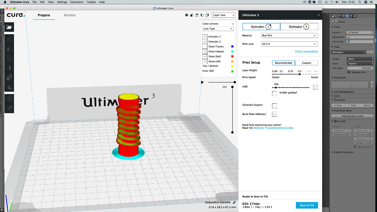
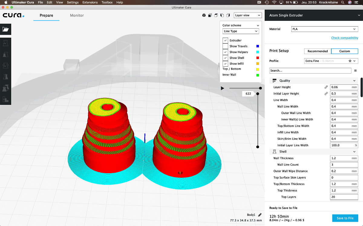
The reference dimensions that I want to check is the diameter and the lenght of the worm gear, 2.31 cm and 6.71 cm respectively. The configuration in Cura were setted up to get a fast prototype on the 3D printer, so no support, 0.2mm layer height at 10% infill: 1h 17min: it's FAST for such a complex shape.
The printout came out quite nicely. We see the general shape of the globoid and I get the feeling of the finished product. Because it was printed without any support, the underside leaves a lot to be desired, but that was expected.
Measured with a caliper, the dimensions are spot on. Now I know that I can make a profile in Blender and it will be usable. The caveat being that if I make a mistake, I must redo everything since this software is not parametric.
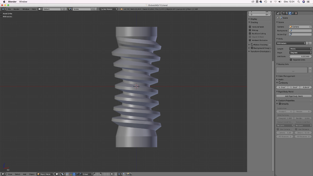
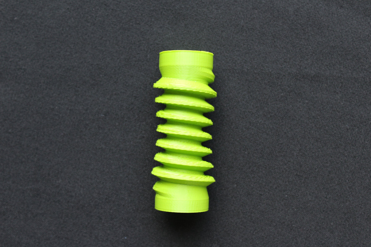
This first print gave me a first impression of what the worm gear will look like. It was also a warning of a big problem that I will have to deal with: I have a nice profile on the lower part of the gear but no so of the upper part.
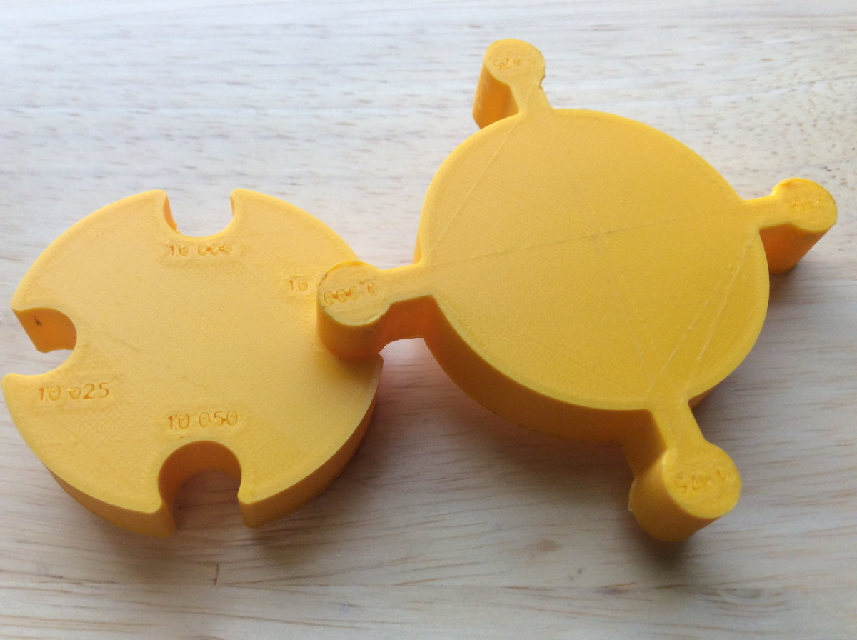
Testing the printer for precision
Next on my schedule was testing the precision of my printer. My favorite is a delta printer, Atom 2.0, recently upgraded to 2.5. I also have access to an Ultimaker 3 and a Ditto Pro. The Ditto Pro was not considered for this test for various reasons (see Print a test part for 3D printer.). For the test I used the file provided by Lars Christensen for this very purpose.
The purpose of this exercice is very simple: how precise is my printer? All manufacturers claim that their products can go up to .06mm. But this is the degree of precision of the layer thickness. When I'm doing engineering parts with tight tolerances, I want to know what my machine is capable of. I downloaded the Lars's gauge and made a print on the Atom and the Ultimaker.
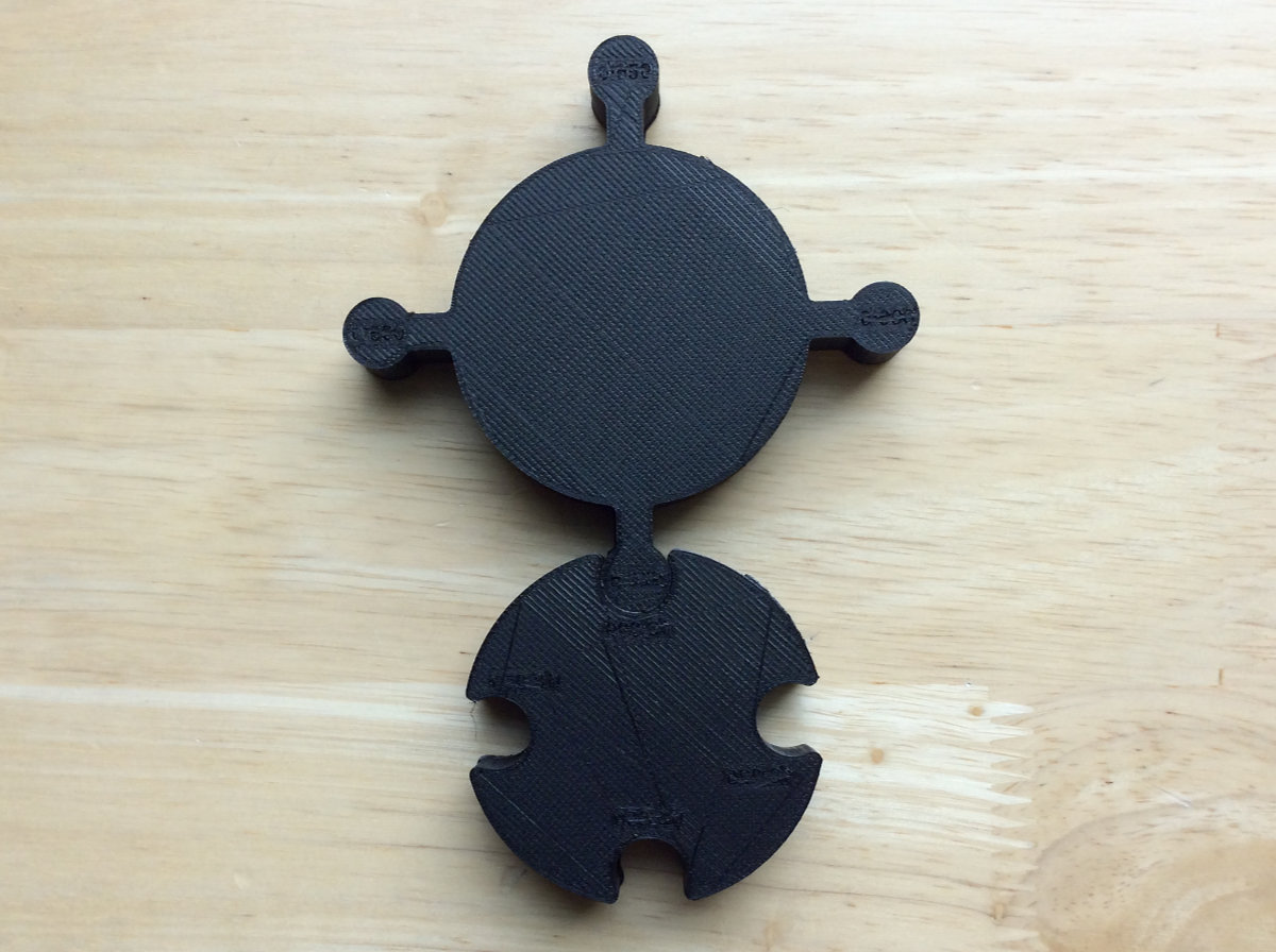
The results didn't surprise me with the Atom: the gauge fit perfectly for all the gauges. So now I know this machine is precice with a tolerance of ±0.025mm for a diameter of 10mm. For the Ultimaker 3, contrary to what I thought would be another winner, none of the pegs fits into any hole! In fact, trying to remove the peg from the round hole melted the two surfaces together because of the friction! This was a surprise. Considering that this is the company's flagship product, I made another try and adjusted the Ultimaker before doing another test. There may be an explanation of this surprising result: maybe I made an error when doing the adjustment on the vernier reference chart provided by the manufacturer.
This results gives me the assurance that the Atom is dimensionnaly precise within the range of 10mm. For larger prints, I will have to redo this test with a larger gauge. The Ultimaker can be useful for parts with less critical tolerances.
Making the worm gear
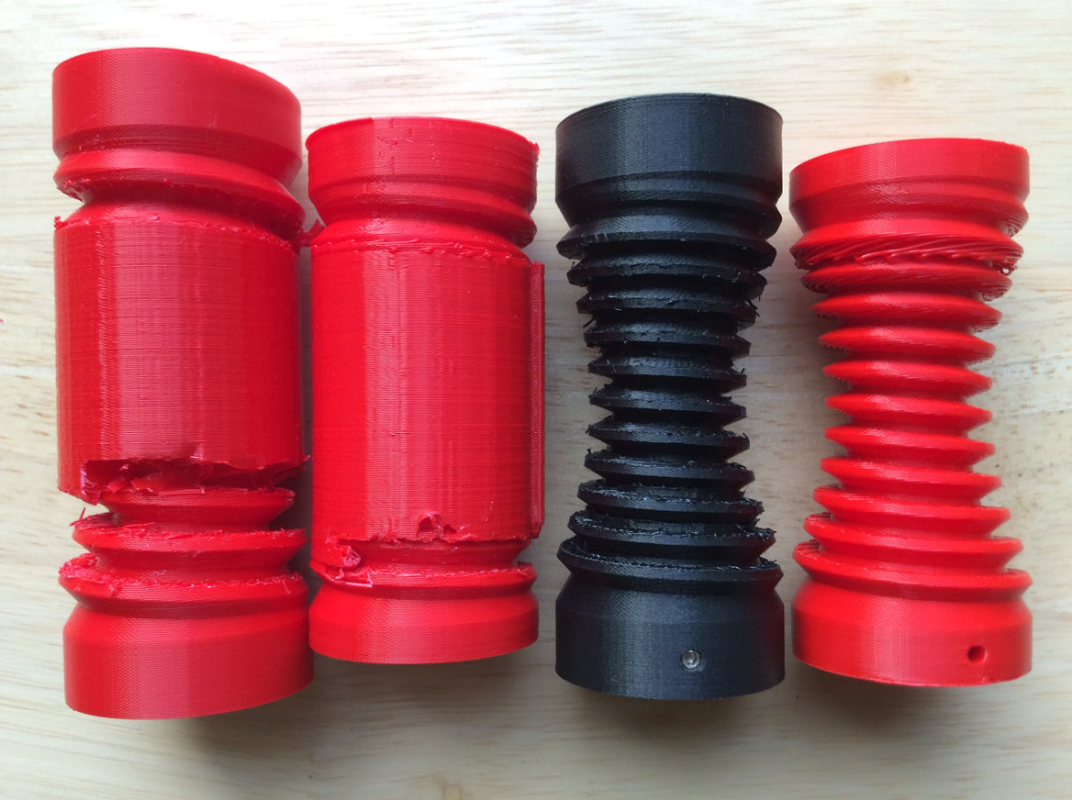
Now's the time to go to the printer and make some prints. I made a first worm gear without any support and it gave me a good result but I had to deal manually with the gear profile. The results proves to be less than satisfactory. The bottom half of the worm was perfect with a nice profile that makes a tigh contact with the gear. On the other hand, the top half was prone to material drooping because of the gravity. I tried to mitigate the problem with finer layer height without any success.
Some testing
Over the next few weeks, as time was available during my full time job, I made many worm gears, trying hard to get satisfactory results for the upper part. Many times over, I tried with different types of supports, with and without floor and ceilings. All failed, or were doomed to failure from the start. The main problem is that support creates bumps on the surface of the mesh. Those bumps must be dealt during post-processing and this takes time. The surfaces must be sanded smooth and precisely. And I must be carefull when I removed those said supports and this takes time, precision, and, as I learned, patience.
I had to find an optimal solution to my problem. An obvious one would be to print it with a resin (SLA) printer, but I don't have access to one. Another way would be to use PVA and place the part in a bucket of water for a perfect print. But I must have 1.75mm and my provider don't have it in stock. On the other hand, I can make it with the Ultimaker but I know that my design will not be within the tolerances.
The Solomon Solution
Well, a solution came to me during the night: why not cut the part in half? No supports needed, perfect profile. I have to align the parts but this problem can be dealt with by making a D-shape central hole for the shaft that will power the worm gear. At the same time I've designed a 2.5mm hole that will be tapped for a headless screw that will lock the worm gear into place.
Since I do not have a D-profile shaft yet, I made a quick one out of PLA to align the two halves together and glued them for a perfect result.
Designing The Rocker Box (again)
Now's the time to turn my attention to the Rocker Box. I've learned from the first prototype that more often than not, the side holes are used as handles so why not design handles for this version? Since Fab Academy, I've learned about the Slot option in the sketch menu. Also, I want to change the profile of the front and back panels for a more organic and symetric look.
The making of the MkII design
As a starting point, I went back to Lars Christensen's Basic Tutorial series on how to model a dovetailed drawer with Fusion, which is basically what I'm doing. I started out and was about to finish when I hit a wall: I was doing dovetails on the side AND on the bottom and this required a particular approach. And guess what, I had to rethink my approach and redo my design. By then it was almost automatic; I knew what to do and where to be careful and it paid off handsomely. Besides, I fully understand what the project command is and used it everywhere.
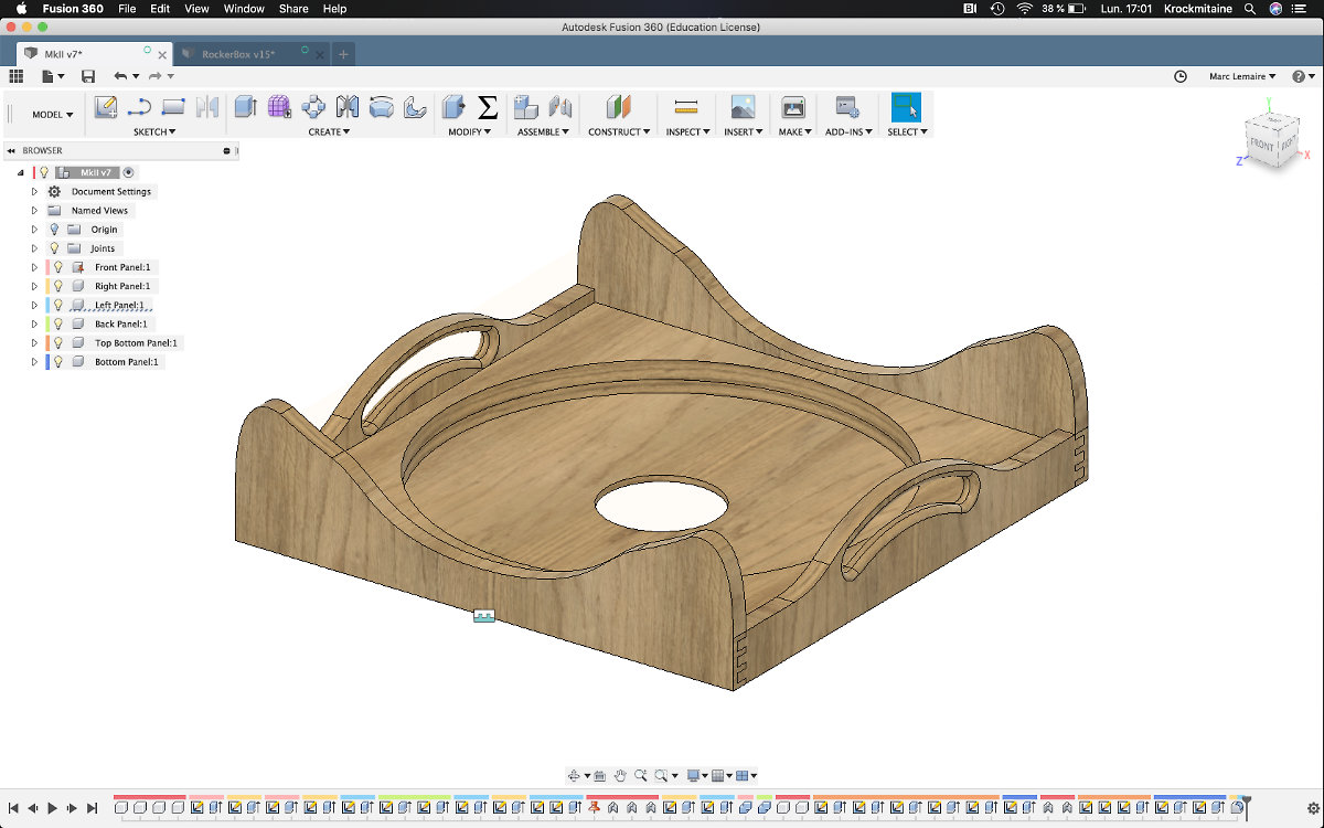
I finish the design with the interior pockets and the central hole at a depth of .5" inch. The rib idea is a good one but having a uniform platform for the electronics will be more useful for me, beside a slight gain in manufacturing time. At the last step, I added the dogbones to all the intersections once I'm sure everything is ok (is it?).
