Embedded Programming
Week 9
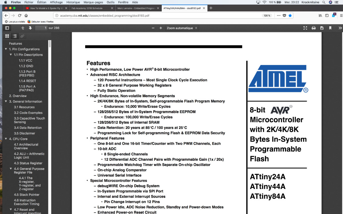
This week's assignement is mainly an intellectual endeavor as we have to read the data sheet of a microcontroler... and try to understand what it can actually do.
Tons of info for a small chip!
Technical documentation, by it's very nature is very dry to read. Especially made for experts, it's not easy to understand on the first try. Concerning the ATtiny44, the data sheet extends to about 280 pages. And it's only a microcontroller! I'm surprised that this documentation is so extensive. Nowadays, companies tend to hide the technical specs to prying eyes. Let's get our feet wet and proceed with the reading.
The cover tells all
On the cover of the page, there's only the company name, a description of the product and the product's format. All this on the right side of the page, on the third column. The main page is full of the technical features of the ATtiny family of microcontroller. I can't possibly describe everything in this document but I will note what I know about chip architecture. To start, it's high performance, low power of this 8-bit microcontroller. It's an Advanced RISC architecture (compared to the CISC architecture of the x86 family from Intel for example) that is capable of executing 120 instruction in a single Clock Cycle Execution (it's the thing that RISC architecture do). We then learn that the memory retention extends for more than 20 years at 25°C. It has an on-chip temperature sensor, an internal oscillator, 12 programmable inputs/outputs lines. It can operate with as little as 1.8 volt! but can use the standard 5.5 volt with proportionnal increase with speed in proportion of the voltage. It can operate from -40°C to +85°C, so it's an ideal candidate for operating a telescope during those beautiful summer nights as well as those cold, but magnificent winter nights. It's also low on power consumption as this one need only 210μA at 1.8 volt and 1 Mhz: a watch battery can power it!
Where I go deeper into the doc and start to get puzzled
The Block Diagram
The block diagram described the structure of the chip. I can understand the purpose of some of these like the port drivers, the oscillators and the SRAM memory but I don't understand (yet) the purpose of the so many timers, the stack pointer and the interrupt unit. I can guess the fonction from the descriptive titles but not much more on how it operates, and the connection between the programs and the hardware.
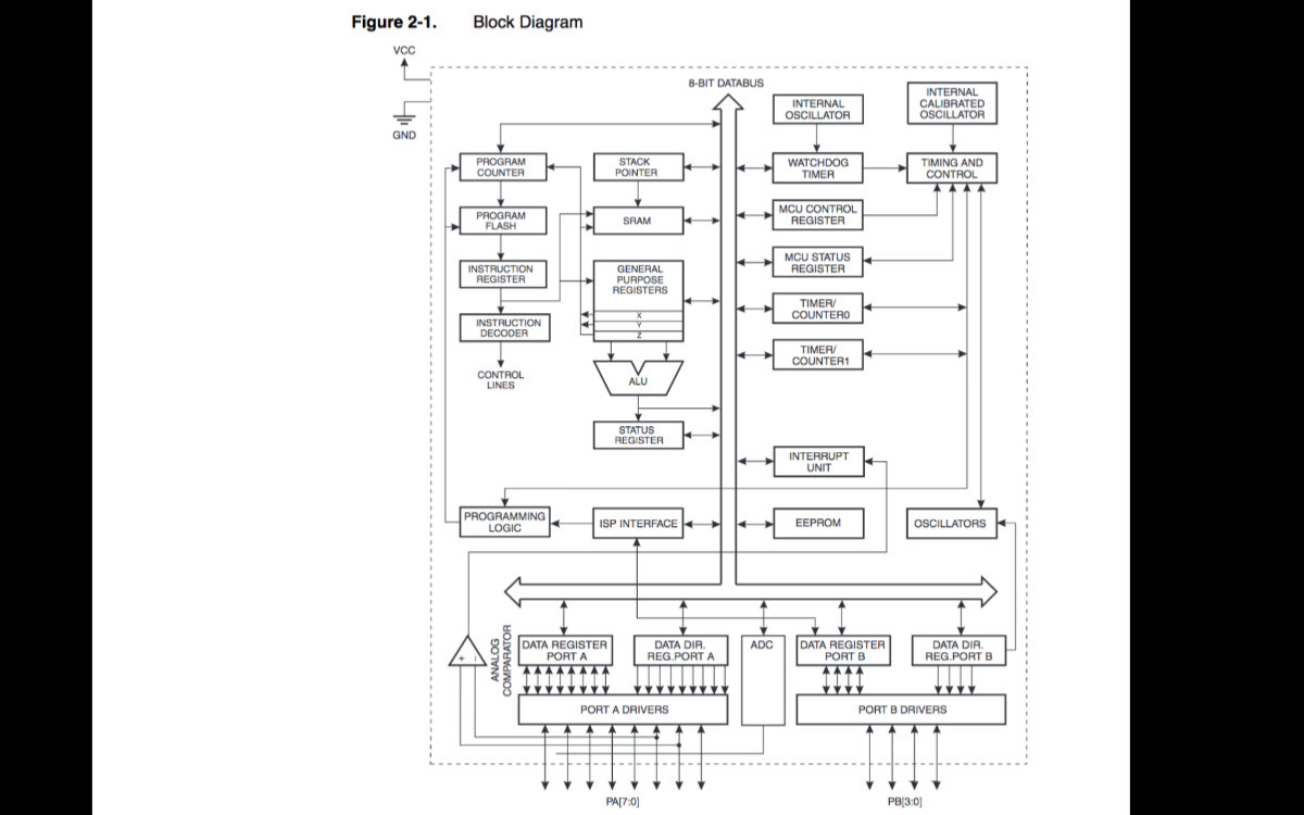
This is one of two diagrams that are the stepping stones to understand the ATtiny chip. But the most useful one right now for me is the pin diagram.
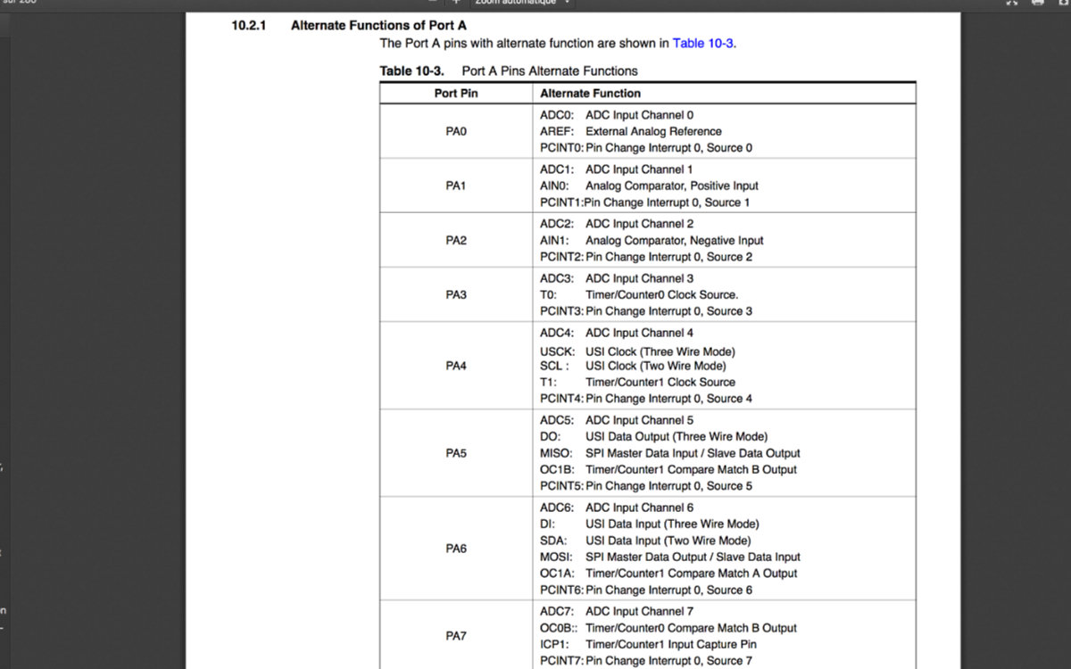
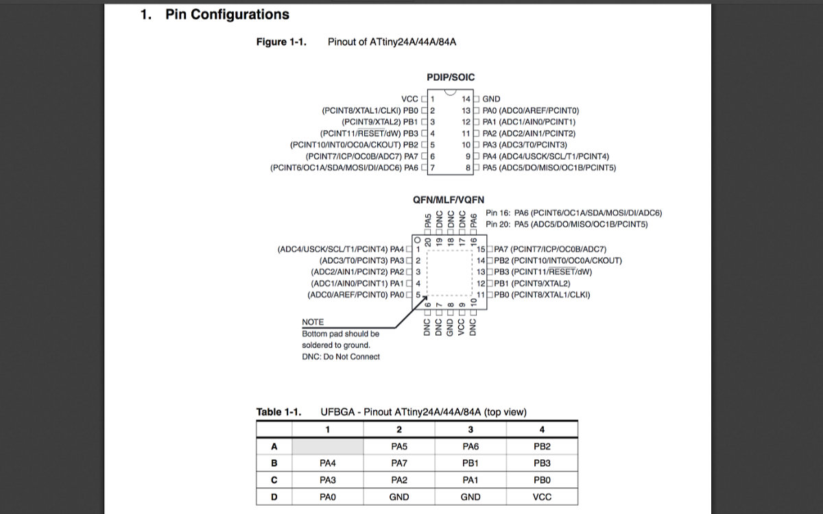
Understand the ATtiny by it's pins
All this information was becoming much noise but the secret ingredient to understad all this is read the documentation and get some hands on experience. After a few weeks, you get more knowledge about the chip. This strategy paid off as I know more about the board as I worked on different projects and came back with more understanding of the going on of this chip.
When I go the the pins section and what they do (Chapter 10.2.1, Alternate Function of Port A), it's much easier to understand the chip by the pin numbers. For example, when we look in detail at Table 10-3 Port A pins Alternative Function, page 60, we found a more descriptive table than the pins configuration of figure 1.1, page 2. For example, we see: PA5 MISO: SPI Master Data Input/ Slave Data Output. So I see the connection between the header pins in a Eagle sketch and this specific input to pin 8. Those first connections that we make in Eagle are all related to this spec sheet.
Also, when we put this data sheet in conjunction with the ATtiny pinout table available on Github, we see that we can easily translate the pins from the Arduino board to the ATtiny44. If we take the previous exemple, the MISO pin is part of ISP interface and is located at pin 8 (Port A, pin 5). But this pin can is the equivalent of pin A5 (Analog 5) on the Arduino board. We can do the same exercice with pins SCK, RESET, MOSI that we need for ISP interface. With this schematic in hand, we can easily transfer a sketch from Arduino to an ATtiny chip and create our own custom made board with Eagle.

Programming the board
As our board has been completed in a previous assignment, this week's assignment was to program said board to do something. With the frustrations and delays that I suffured for the making of the Fab ISP, I was uncertain of the outcome of this week's task, especially after reading through my Electronics Design assignment, I worried a lot about programming because this takes time, and that we don't have in really large quantities.
But I put myself to work and picked up my freshly done FabISP and wired the board with jumper wires. Since I kept my board with the jumper, FabISP provided the necessary 5V. I only needed to connect the headers pins to their reciprocal port on the Hello board. (That's the reason that I kept the jumper on).
With such a simple setup, after the obligatory double triple checking to protect against any brownouts (I don't want to do those boards anymore), I connected the usb cable. I may sound paranoid, but after so many failures, you start to think like you're sending a satellite to space.
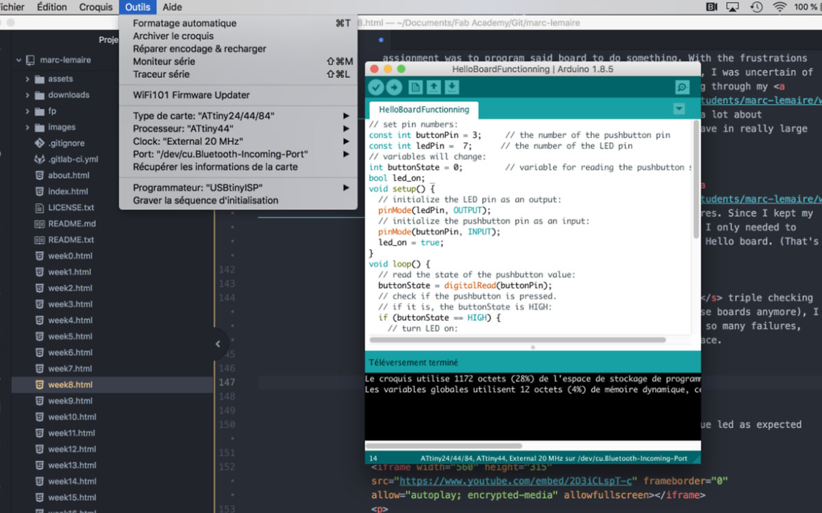
I connected the Arduino by following this tutorial, where most people goes to it seems.
The board went alive with no problem and saw a bright blue led as expected instead of the feeble light that I saw the last time.
The blinking light was expected, but pressing the button did nothing. I had to program it. I used the same program as the last episode:
// set pin numbers:
	const int buttonPin = 10;     // the number of the pushbutton pin
	const int ledPin =  6;      // the number of the LED pin
	// variables will change:
	int buttonState = 0;         // variable for reading the pushbutton status
	bool led_on;
	void setup() {
	  // initialize the LED pin as an output:
	  pinMode(ledPin, OUTPUT);
	  // initialize the pushbutton pin as an input:
	  pinMode(buttonPin, INPUT);
	  led_on = true;
	}
	void loop() {
	  // read the state of the pushbutton value:
	  buttonState = digitalRead(buttonPin);
	  // check if the pushbutton is pressed.
	  // if it is, the buttonState is HIGH:
	  if (buttonState == HIGH) {
	    // turn LED on:
	    digitalWrite(ledPin, HIGH);
	  }
	  else {
	    // turn LED on and off:
	    if (led_on) {
	      digitalWrite(ledPin, LOW);
	      led_on = false;
	      delay(50);
	    } else {
	      digitalWrite(ledPin, HIGH);
	      led_on = true;
	      delay(50);
	    }
	  }
	}
But It did nothing. I received help from George as he told me that he had this problem but he found the solution by changing the pins description, changing the lines to this:
const int buttonPin = 3;     // the number of the pushbutton pin
const int ledPin =  7;      // the number of the LED pin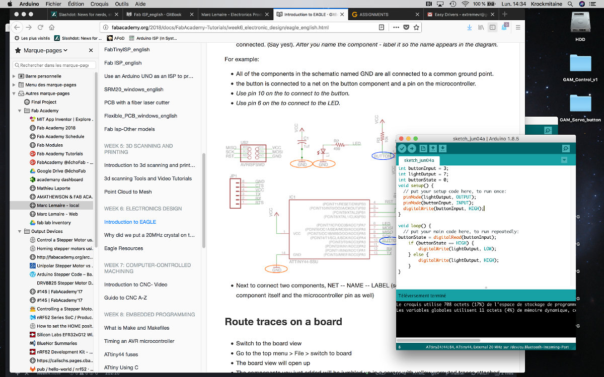
I uploaded the code and the light was off, only functionning once I pressed the button! How cool is that! (But you don't know the feeling until you program a microcontroller)
