Computer-Controlled Cutting
Week 4
This week's lessons had a group and an individual work assignement. We had to work out how to characterize our laser cutter with different materials and create a press-fit construction kit. We also had to cut something on the vinyl cutter.
Laser cutter
This is a new machine for all of us. I started working with George Hanna with the laser cutter by figuring out how to properly setup this machine with different material with a SVG file that was done the day before.
Vinyl cutter
This week, we have as an assignement to cut a simple pattern with the vinyl cutter. Being into space, it's no surprise that I want to cut a logo from SpaceX and put it on my computer cover.


To the cutter!
I finally cut my image with the vinyl cutter. I made a few mistakes, especially related to the cutting force of the knife, not going at a strong enough force with 50 then 80gfs. I eventually got my sticker with a configuration of 80 gfs and a speed of 4cm/min.
Setting the machine
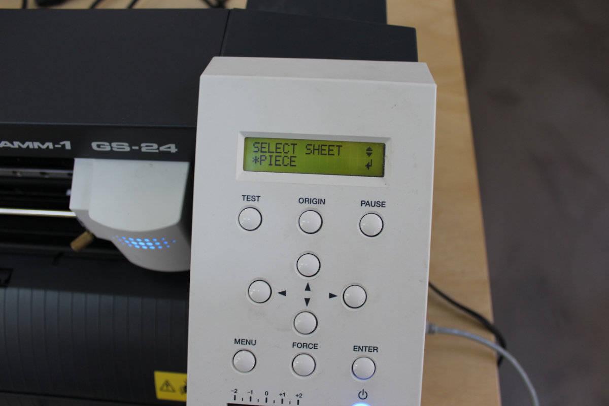
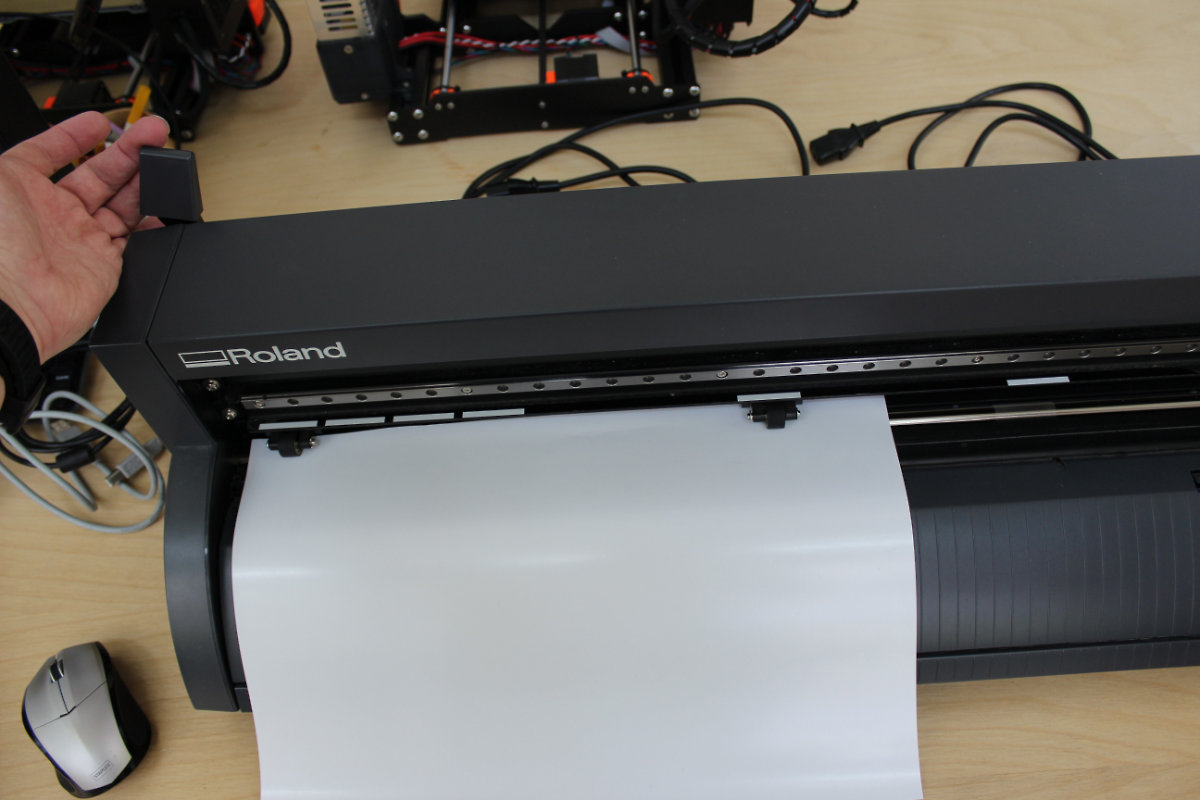
Setting a vinyl cutter is a pretty straitforward affair. On the machine that I used (Roland GS-24), I press "Menu" then with the down arrow I choose "*Piece" for a piece of vinyl. I then place the piece on the rollers, being careful to place the rollers on the white marks (first one on the left).
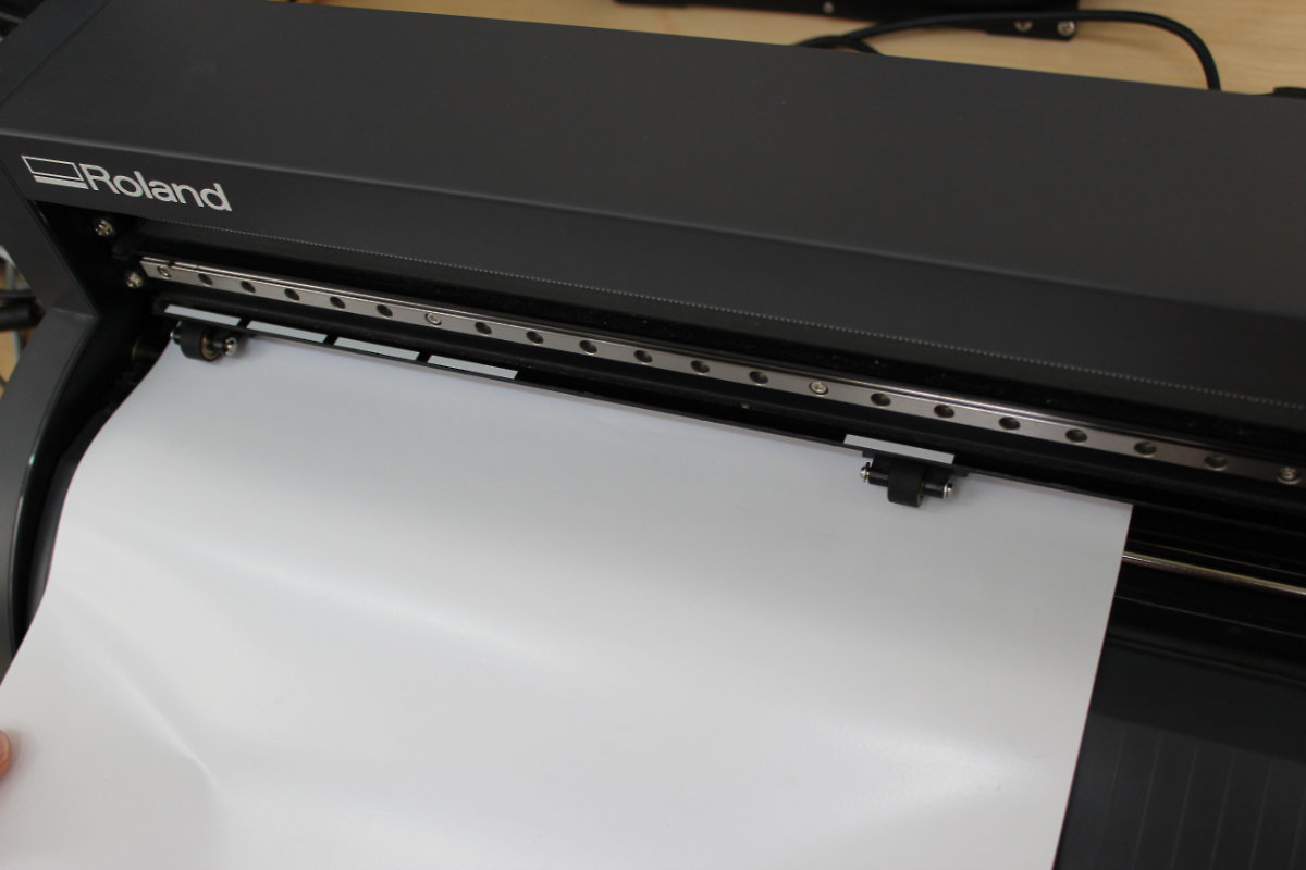
Once the piece of vinyl is placed, I secure it by pulling the lever toward me. Once this last step is done, I only had to send the file from the computer to the machine.

Lessons learned
Today's main lesson was that I lost time because I was so concentrated into learning and doing it all that I completely forgot to document the process. AI had to retrace back my steps because I forgot to take screenshots while accomplishing this simple assignment. I litterally spend the whole day redoing all those steps. As an habit, I never forgot to save my files before shutting down a program and I shutted down the Inkscape "saving" the file. It's only after a double checked for the heck of it that I saw that said file wasn't saved and I had to do it again. Not my day. But this time, it took me two minutes instead of hours. It's is a hard lesson that I learned today that I hope to never repeat.
Also, I notice that Inkscape, when it transforms from raster to vector, creates two layer profiles on top of each other. It's by carefully looking at the cutout that I noticed that the cutter was doing two passes with a small discrepancy, creating ragged edges. This creates bad cutouts and I started to investigate other solution. Not having Adobe's Illustrator, I tried to transform the initial png with Affinity Designers, a software that I bought a few years back. I had no luck as this software can't (yet) transform a raster image to vector. So, I will use Inkscape for the moment.
Characterisation of the laser cutter
As a first group assignement, we had to characterized our laser with differents type of materials. With the help of George, Geoffroi and Alec, we decided upon a test grid composed of increasing power output and started to make some tests.
We're happy when we see our first results emerge in front of our eyes.
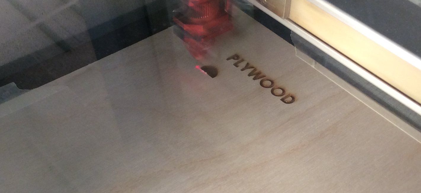
But the results weren't satisfactory as we had too much power and we were burning the wood. Also, we had some issues with the graduated spots as those didn't showed up.
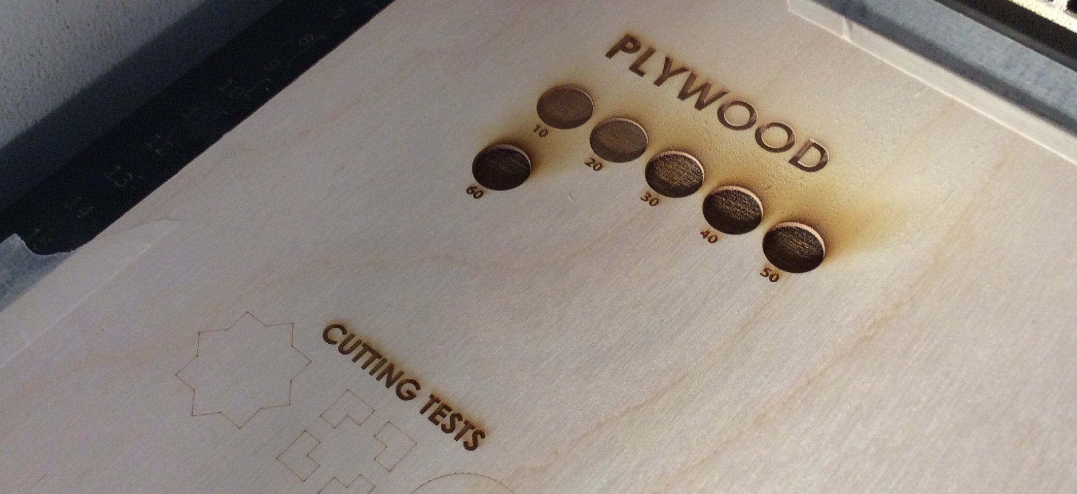
We first tackle the problem of decreasing the power of laser in order to have a nice surface without any burnt areas.
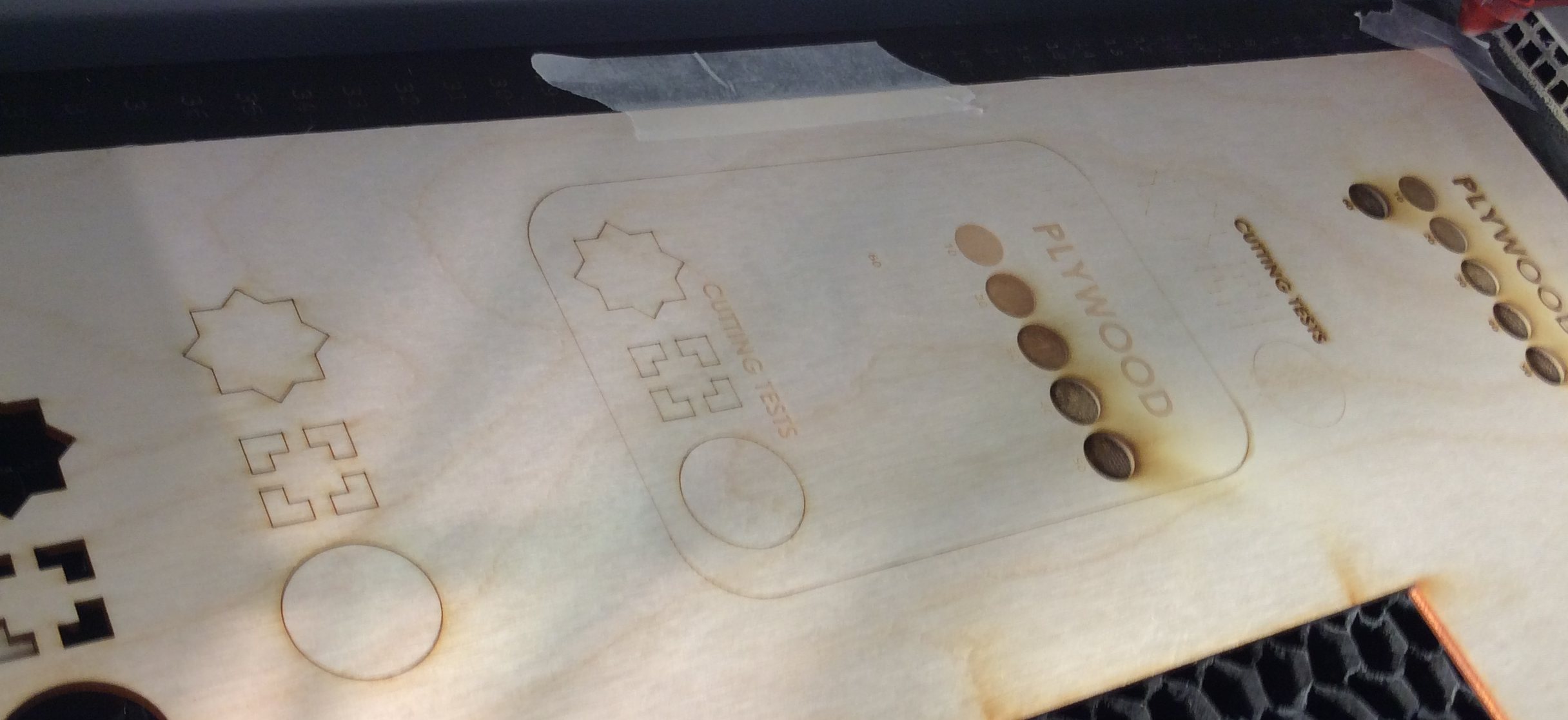
We then proceed with the graduated areas and eventually came up with the solution of doing two passes, one for the graded areas and one for the engraving and cutting process. This problem arises because the laser cutter has difficulty with dealing with shaded areas.

Engraving paper
I have an origami book that shows how to fold 3d origamis. The author recommend the use of a vivnyl cutter but I'm thinking why not use a laser cutter and delicately engrave the fold. A laser has the option of doing precise cut on the reverse side of the paper. With this idea in mind I made some test and came up with some interesting results.
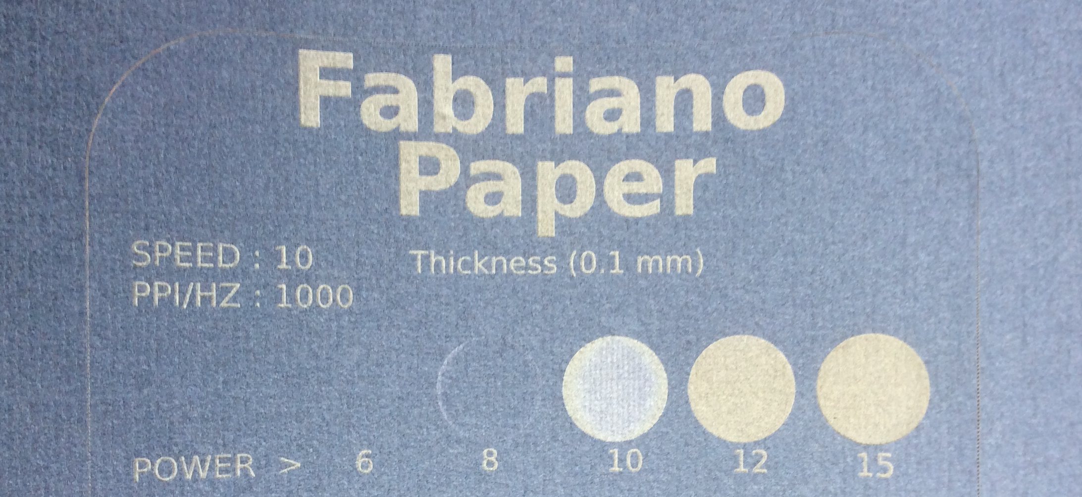
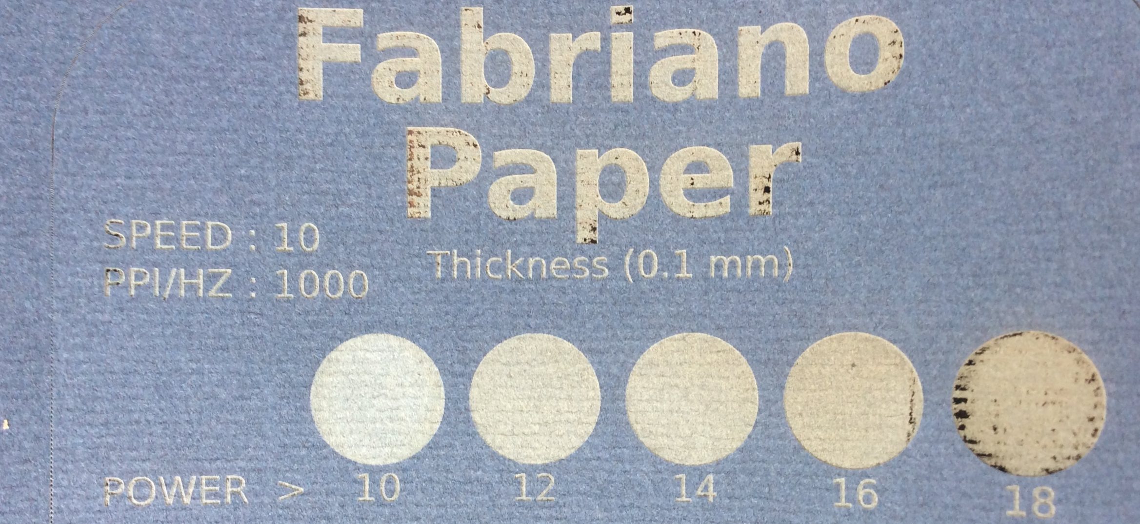
I started with very conservative values as a starting point. For this first iteration, I've increase the power to 15 then 18. At 18% of power, it's almost like a spider web and way too thin. 15% is almost too powerful. My next text will use 12, 13, 14, 15 and 16%. Since I really care for fold for this, I will get rid of the graduated scale and put some line and do a reverse side. Also, I will decrease the speed of the cutting down to 10 while maintaining a power of 60 and see where this test file will lead me to.
Press fit contruction set
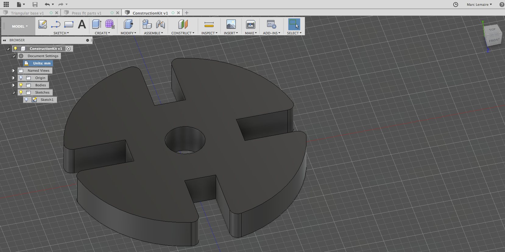
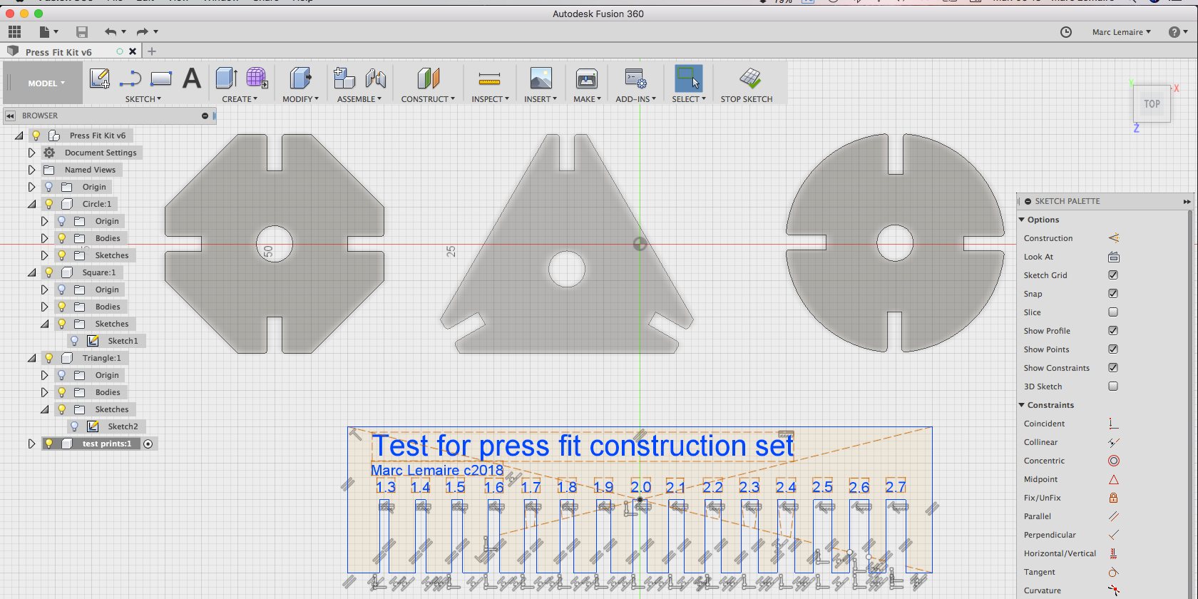
I've worked a little with Fusion 360 before starting the FabLab Course but I manage to forget just about everything that I've learned because I didn't use it on a regular basis. I really like the parametric approach that can saves precious time in the future, but I'm not quite there yet and I still have to master this software.
For this assignment, my approach was to construct a simple set of form that can press fit together to create various forms. I've added a central hole that can be use to pass wires for LEDs and maybe create a luminous sculpture. What I really wanted to learn was how to create a centered equilateral triangle with the tips cut off. I discovered that if it's easy to create a sketch with a circle or a square wherever I want, sketching a triangular base requires a more mathematical approach. Once this problem solved, I can use the solution to built the base for my telescope.
The hard lessons that I've learned yesterday weren't repeated today as I took screenshots during my session. One mistake though, at fisrt, I forgot to built my parts using the "new component" menu for my sketches so I started from scratch.
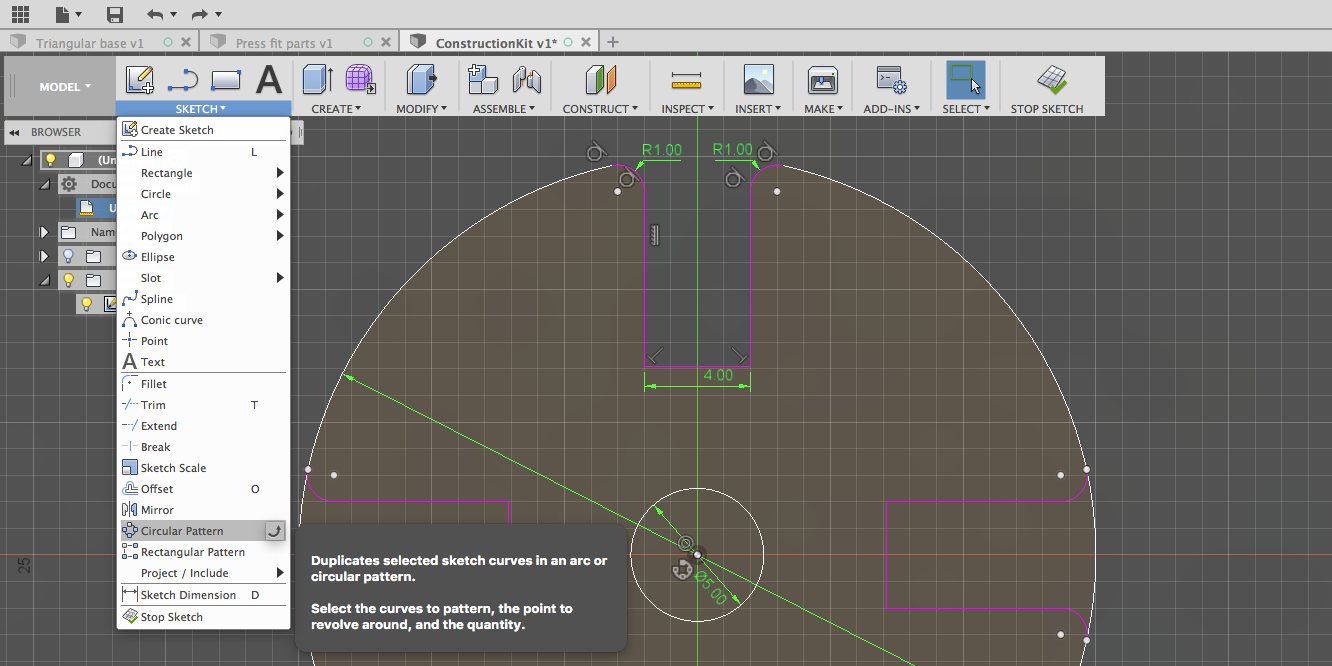
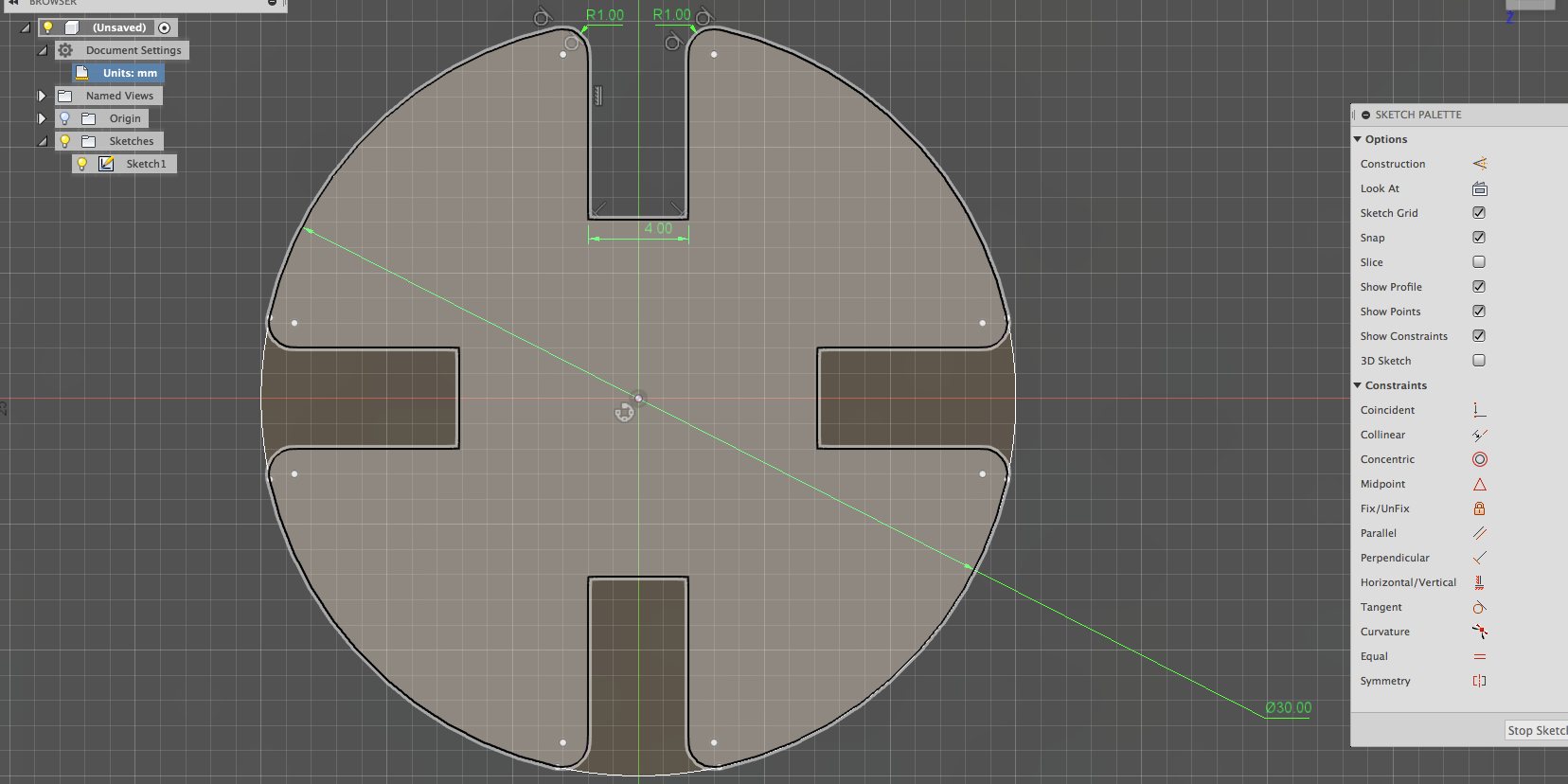

Next step is to laser cut the parts and test!
Before getting some sleep, I remembered that we have to put fillet to the parts, redone the triangle and add a test for print. All these operations were added in my morning coffee.
The laser cutter
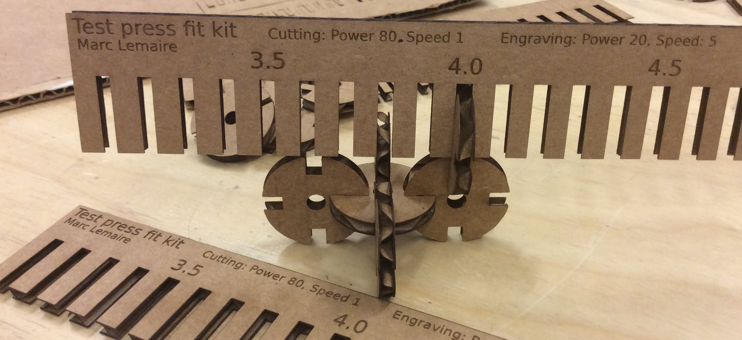
I prepared the file for the laser cutter and everything seemed fine. Took a piece of cardboard that suited my need, calibrated the laser cutter and made my first pass. At first, speed and power were too fast. I decreased speed, then power, eventually coming up to 80 for power, then 1 for speed: a perfect combination that cuts without leaving any trace. The results of the jig reminds more of a comb than a test rig. The results were no good for one good reason: I chose a thicker cardboard, 4mm instead of the 2mm than what I designed!
Back to the drawing board, corrected the depths to 4mm in increments of .1mm to be sure that I will have a press fit of the parts.
I'm on fire!
Although really careful, I loaded a wrong profile. As I was standing beside the machine, I noticed that the laser cutter was making TWO passes instead of one. The time to decide how to stop the machine, the cardboard caught fire. I was so surprised and undecided about the next course of action (pausing the machine, or from the computer or put the blanket) so I called for help. Mathieu came and promptly took the cardboard out and put it in the sink. No damage was done to the machine because of the quick response.
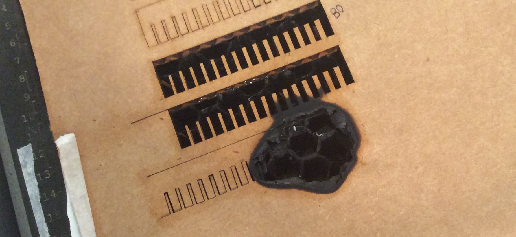
So always be on your guard while operating a laser cutter. And if you see fire, remember to shut down the machine with the power switch.
After cleaning the mess, I went back to my file, increase the width to proper dimension and saved in DXF file format. I opened Inkscape, added some text and export in SVG. This was a big event for me as everything went fine and saw the end result of my work. I went back and added the specifications to be engraved onto the surface of the cardboard for future reference.
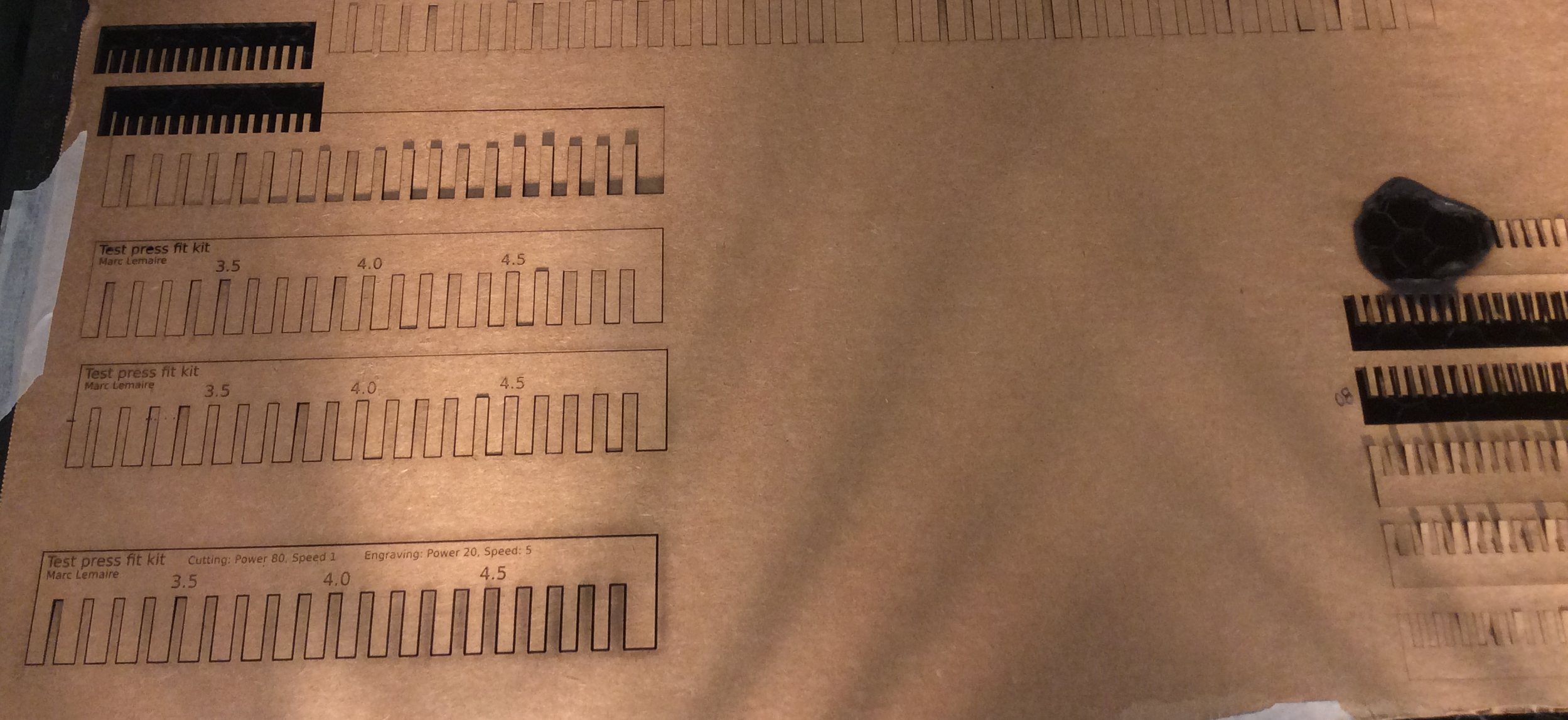
I printed the parts next. I printed them but again, configured for 2mm thick cardboard. Went back, corrected to 4mm and cut. The end results are surprising. The parts goes together at the precise nominal dimension of 4mm. Not noticable on the photos that I took but there is a too tiny fillet of .5mm radius at each corner.
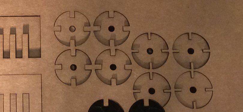
Finally, I was able to make a shape with my parts. There is a really tight fit and I'm amazed at how good the parts looks.
