Principles and Practice
Week 1
Plan and sketch a final project
After talking with my instructor, I got the green light with my project of building a Dobson telescope base with a digitized GoTo system.
John Dobson invented this style of construction as the most economical way for any person to built and own a telescope for observing the night sky. But this type of telescope are generaly used with manual input (pushing) to keep your target in visual. As you get more and more magnification, you have to push with more precision or risk loosing your target. If this happens, you have to re-locate your stellar object, loose time, concentration and lost your eye sensitivity to darkness.
For this reason, adding a motorized digitized tracking system, (or GoTo system) is the most sought after addition to any telescope so you can spend more time observing the wonders of the Universe and less time managing the system.
Description of the sketches
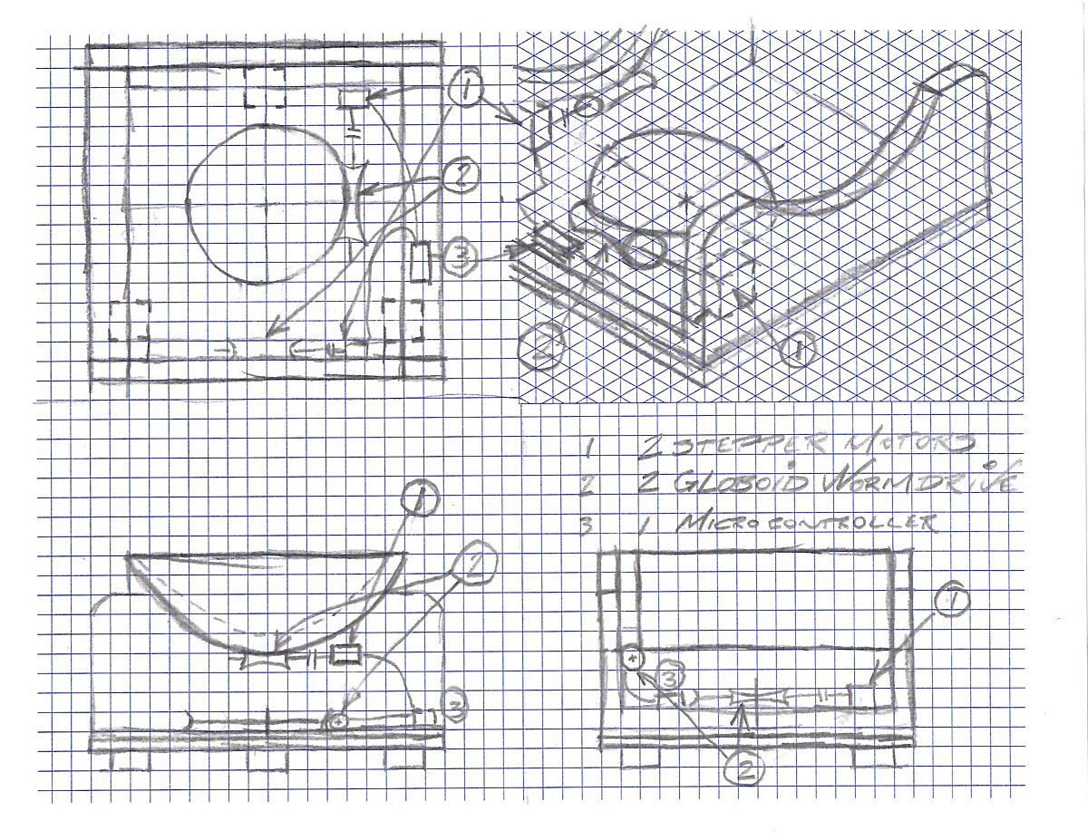
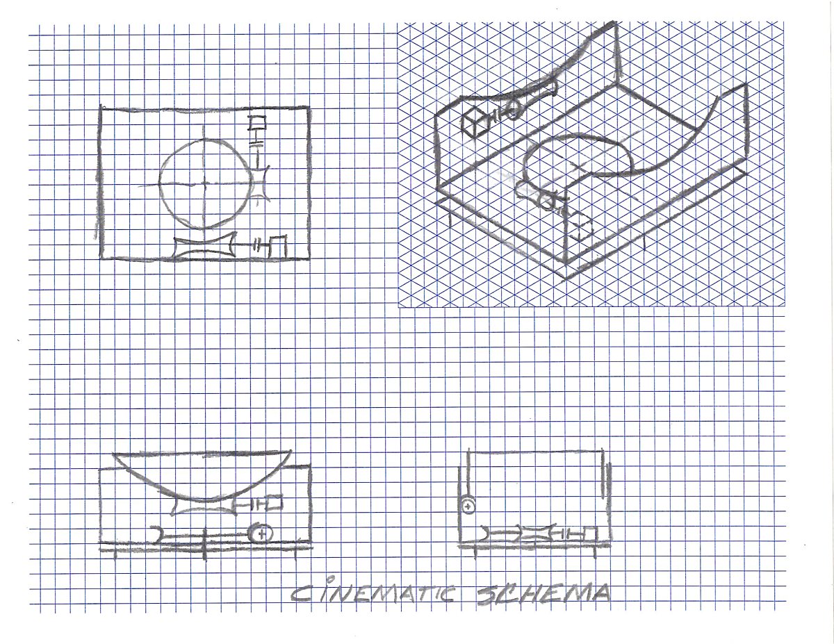
Having a draftman diploma under my belt, I've been trained into seeing in orthogonal view. So I wanted to make a sketch with front, top and right side view. A nice addition would be having a isometric view. Previously, hou had to buy special sheets with the specific grid for your need. Now there's an app for it: IsoOrthoHybridGraphPaperGenerator makes it all for you and you print on demand using standard paper. So I configured a square grid covering three-quarter of the surface and one-quarter with an isographic grid.
I first made a cinematic sketch showing two gears systems for controling the altitude and azimut (or AltAz) mount. This schematic is simple and describe the mechanical nature of the mount. I want to use globoid gears for more contact between the motors and the shaft for more precision, and also for the looks. Those gears, which were previously difficult to manufacture, can now easily be done with 3D printing. Designing the worm and gear pair was previously a difficult task but now it's made easy with the help of a online tutorial and calculator with Blender. At the end of the tutorial, we can make a simulation using Blender's Physics Engine. The globoids may add a level of complexity not worth the trouble and may be changed for normal gear set.
The second sketch is a little bit more descriptive of the way I see my telescope base at the moment. I need two NEMA17 motors that control the drivetrain. Those in turn are controlled via a microcontroller and a driver unit. Hardware wise, the design challenge will be to include the altitude gear drivetrain and motor between the base and the Lower Optical Assembly because there is a big radius (17½"). Softwarewise it will be to design the software so that it can translate the stellar coordinates to Altitude Azimut coordinates that control the motors.