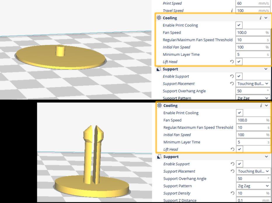
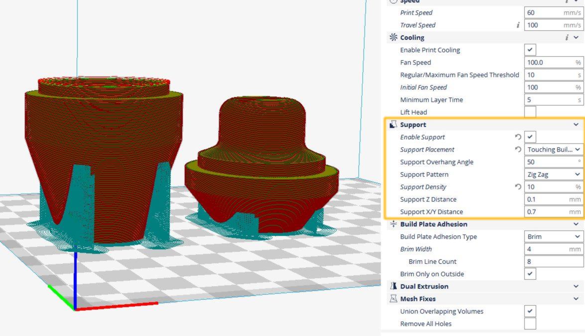
STEP 01 - 3D PRINTING - this step is likely to take a bit of time therefore it comes first. If you consider making many hexagonal casings, I would recommend making a mould out of the first print you will make, and cast from it. Otherwise...
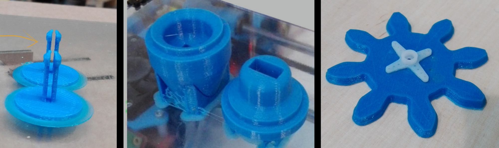
... Find the .stl files ready for printing (as well as design files in Fusion360) --- here --- . Some notes about it to ensure your print come out fine :
For the base, you will need :
- - 2 x "connexionFemale";
- - 2 x "connexionMale".
For each casing, you will need :
- - 1 x "drivingGear";
- - 12 x "pinBlade";
- - 3 x "pinBearing" - according to the quality of your print you might break a few of them before fitting one in, so I would recommend printing a batch of 6 straight from the start - ;
- - 2 x "connexionFemale";
- - 2 x "connexionMale".
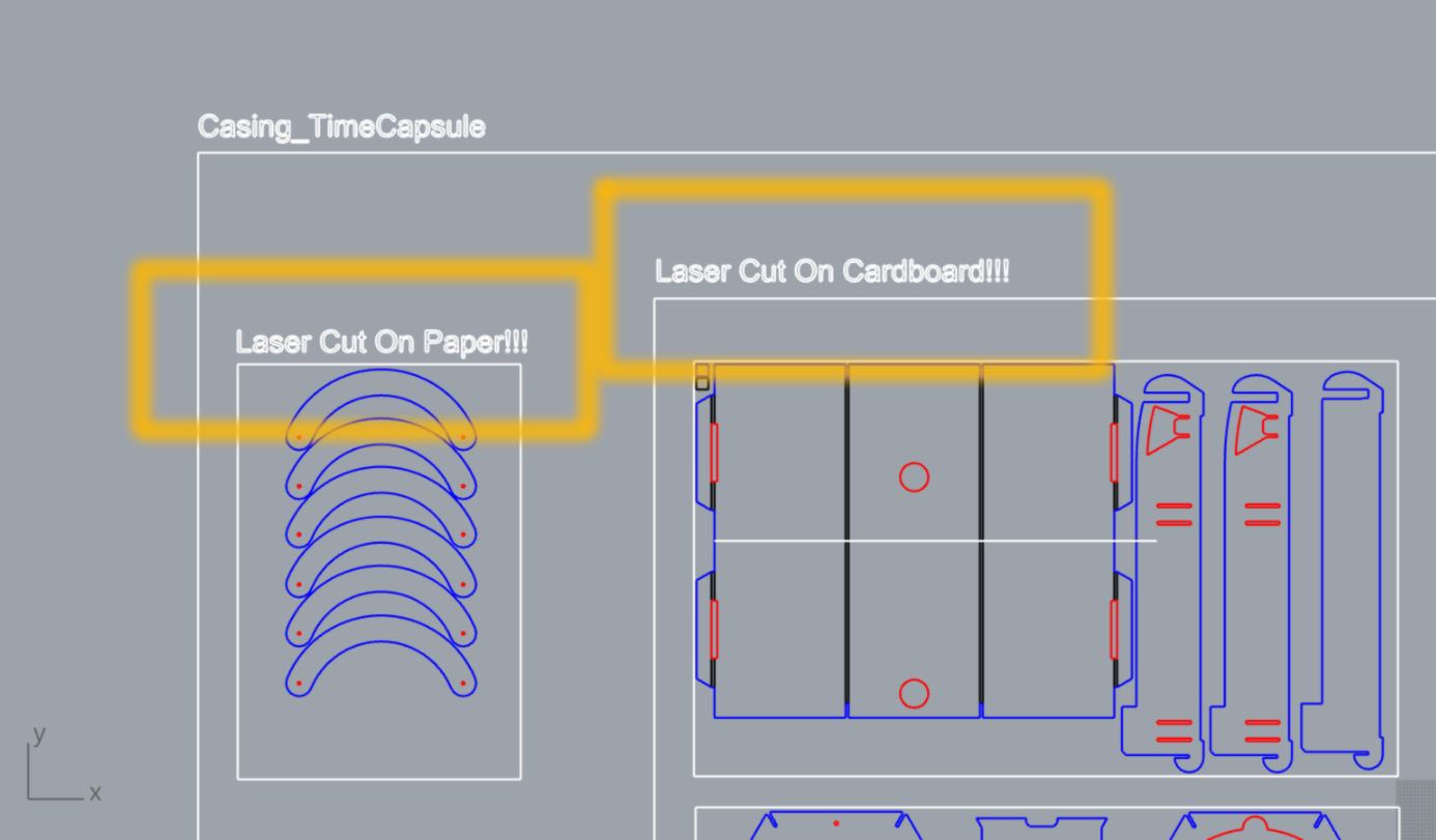
STEP 02 - LASER CUTTING - I used a Trotec Speedy 400 to laser cut all parts. I used two types of materials : 4mm cardboard and 100gr paper (for the iris). If you wish to go ahead and use other materials go nuts, but beware : this is a press-fit kit for 4mm material only - and fitted to the kerf of our laser cutter here : 0.125mm. Apologies, the design is not parametric yet...
In case you are unaware of the kerf of your laser cutter, design a small 10 x 10mm square, cut it, then carefully measure it with a caliper. If you get 9.75mm, you are all good to go!
Please find all the files for cutting (Rhino 6 files) as well as design file (Fusion360) --- here --- .
For the base, you will need :
- - 2 x "1000mmx600mm" sheet of 4mm cardboard;
For each casing, you will need :
- - 5 x "1000mmx600mm" sheet of 4mm cardboard;
- - 1 x "400mmx500mm" sheet of thick paper;
A few comments about it : Cardboard has a a "structural" direction. When cutting and placing the cardboard, make sure the "lines" runs from the top to the bottom of the working plate (vertical). I have not tried to cut my pieces diagonally, it might even be better...
Rhino files : The material that must be used it described at the top of each section :
on the Trotec, lines were etched and/or cut in the following order with the following settings :
For cardboard :
- - Black ( etching ) - Power : 10 / Velocity : 1 / Frequency : 1000 Hz ;
- - Red ( cutting ) - Power : 33 / Velocity : 1 / Frequency : 1000 Hz;
- - Blue ( cutting ) - Power : 33 / Velocity : 1 / Frequency : 1000 Hz;
For paper :
- - Red ( cutting ) - Power : 50 / Velocity : 5 / Frequency : 1000 Hz;
- - Blue ( cutting ) - Power : 50 / Velocity : 5 / Frequency : 1000 Hz;
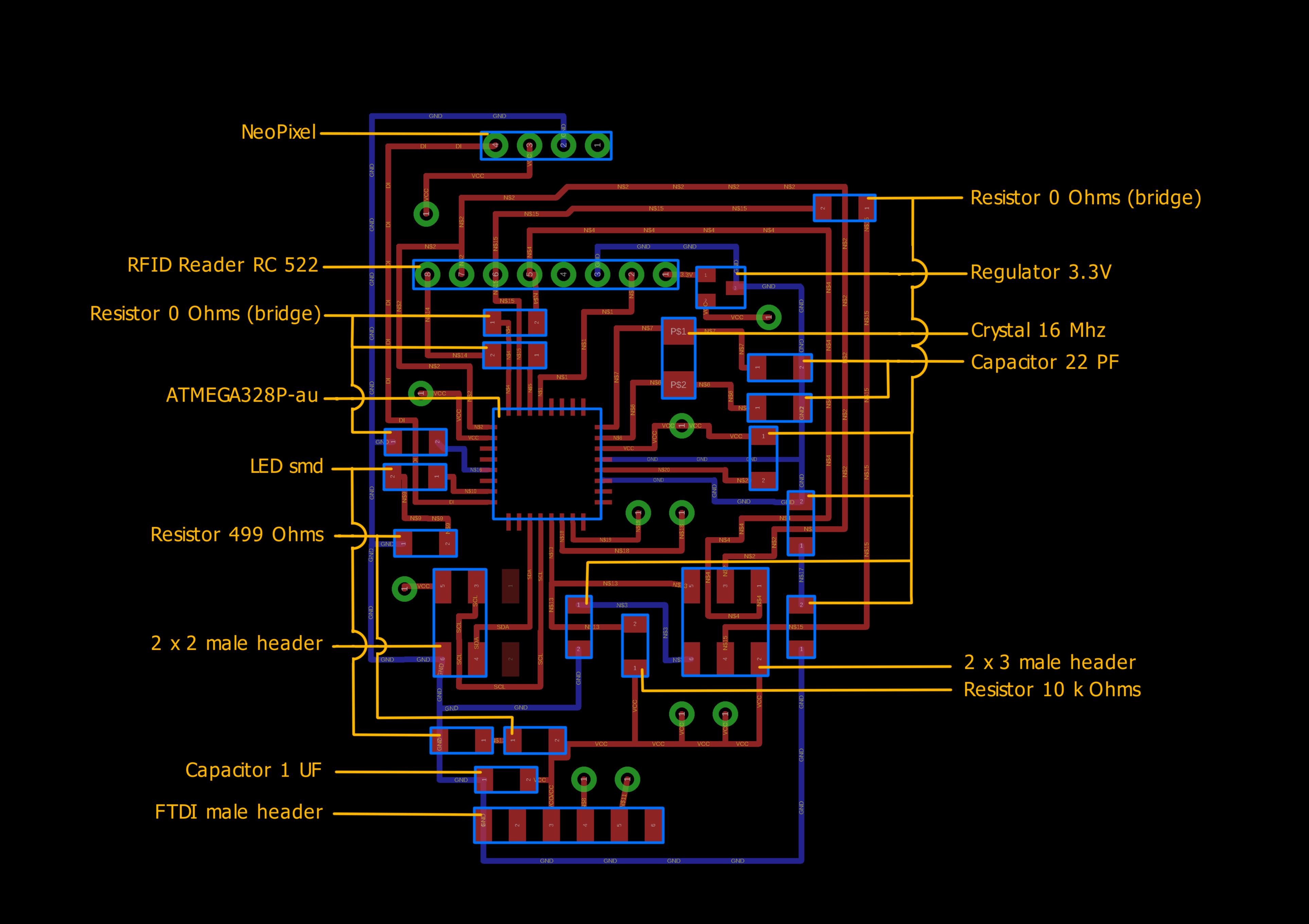
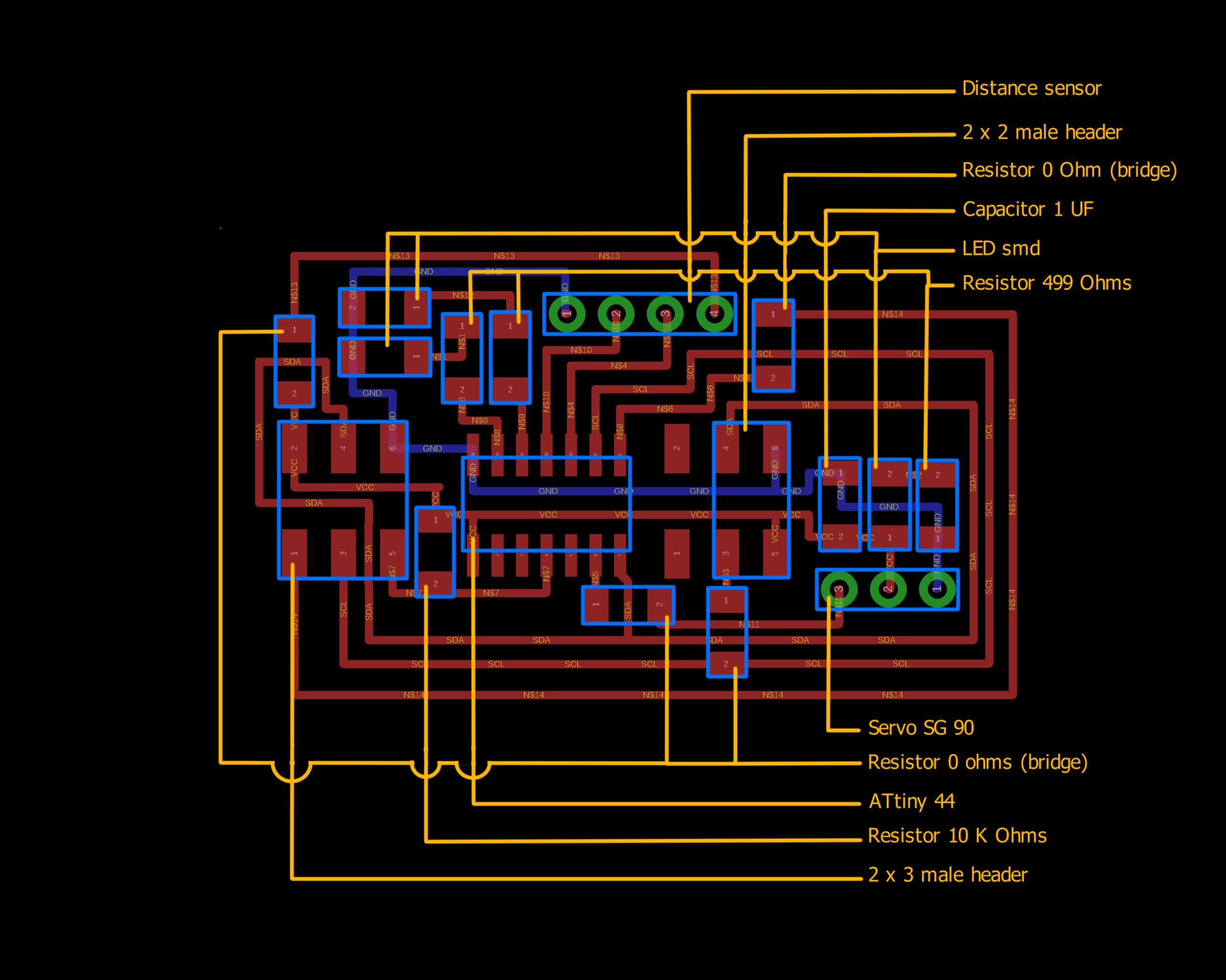
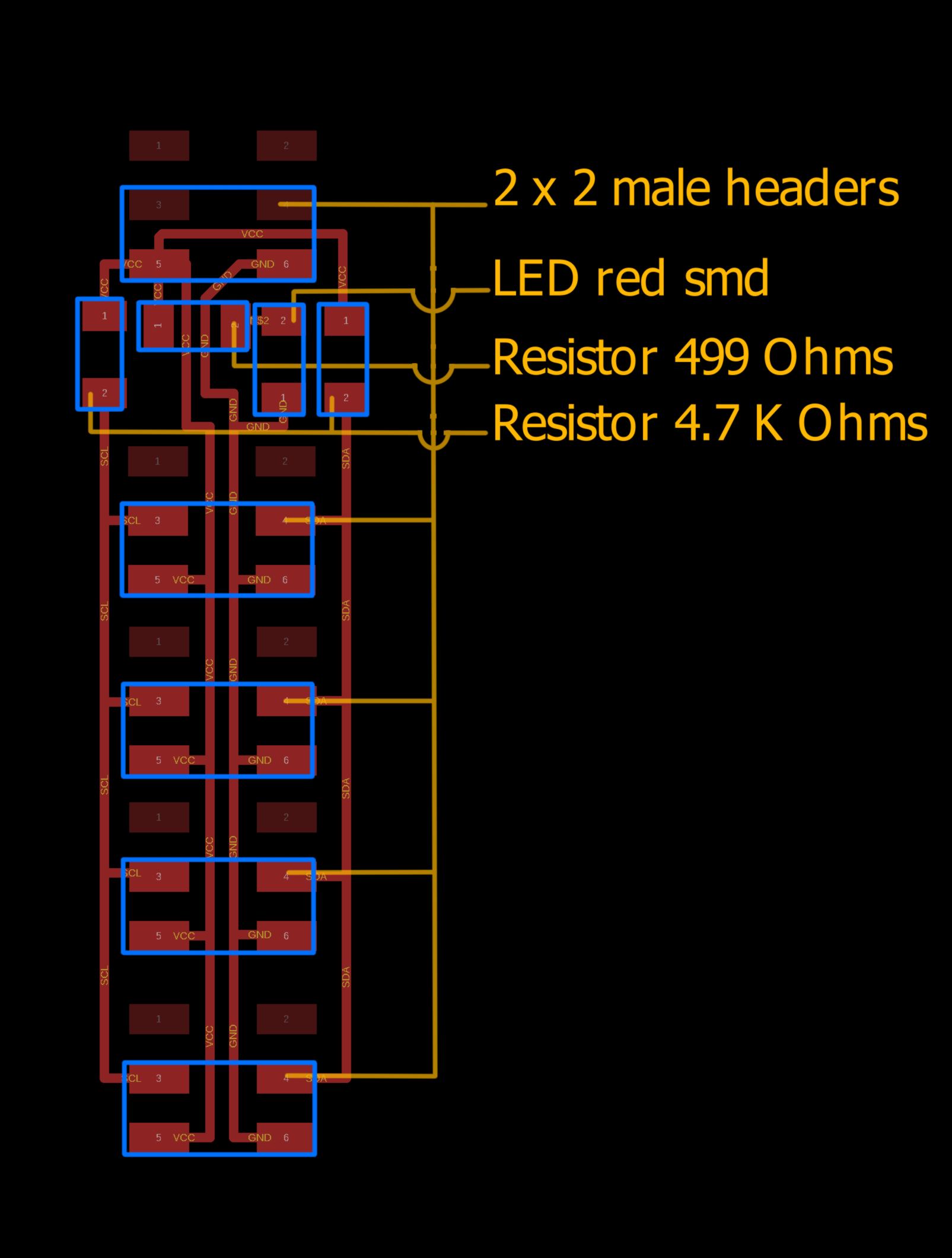
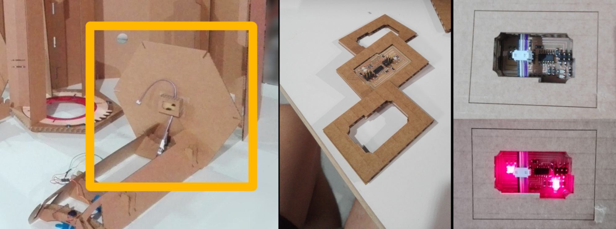
STEP 03 - ELECTRONICS - I used a monofab SRM 20 to mill the boards. all designs are available --- here --- . A few comments about it:
2/ If you use the same milling machine, you can directly use the .rml files. Otherwise, you can import the .png files in fabmodules and get the g-code for your machine from there. Email me if you need a hand : jbnatali@gmail.com.
Find below which component goes where :
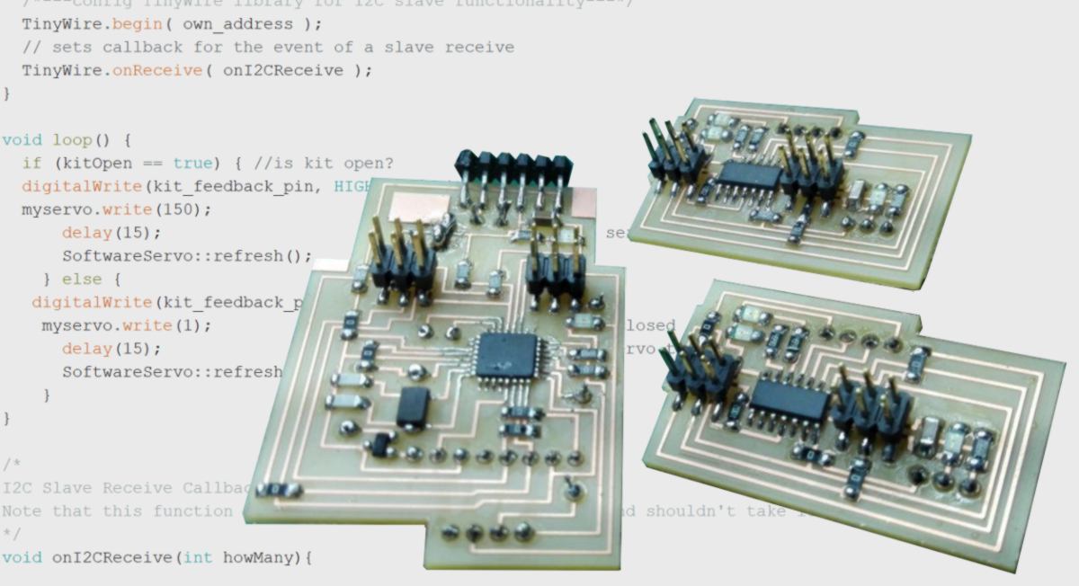
STEP 04 - PROGRAMMING - find the code --- here --- that must be uploaded on the master board and each slave boards after bootloading.
Quick note about bootloading : I used both a programer and an arduino board as a programer to bootload my board. If you don't have a programer, surely you have an arduino laying around. Follow the step described on this page to make it happen.
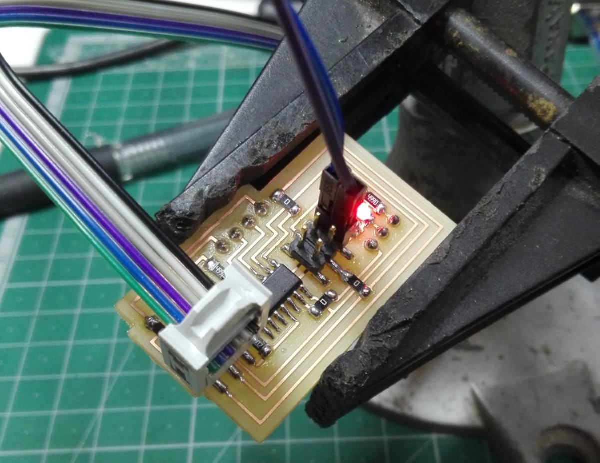
Sometimes the arduino does not deliver a steady amount of energy to the board, so if bootloading does not work even after a bunch of fixing, I recommend to add an extra VCC/GND connection from another power source using the male headers dedicated to I2C programming :
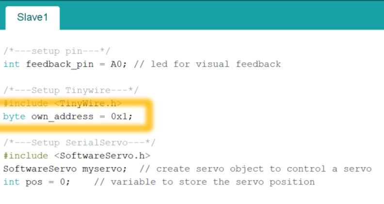
For the programmation of slaves beyond the second one, you need to modify the ID of the slave at the beginning of the code:
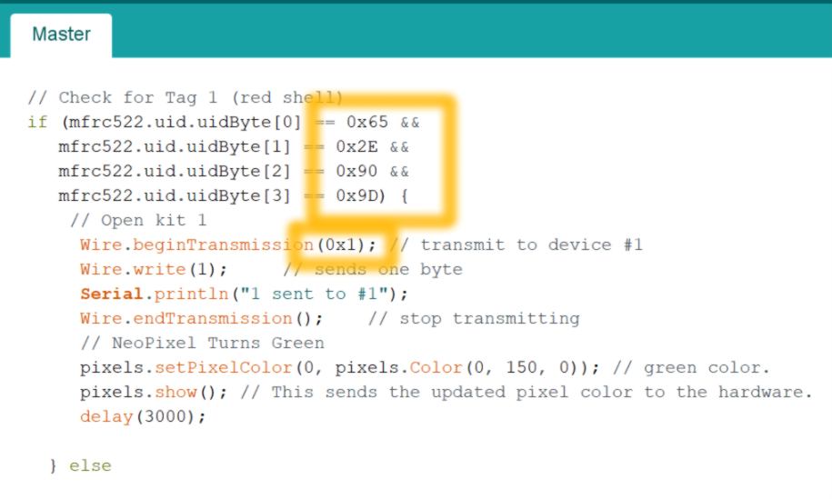
For the code of the Master board, you need to provide UIDs of the RFID tags you use, as well as which casing it will open :
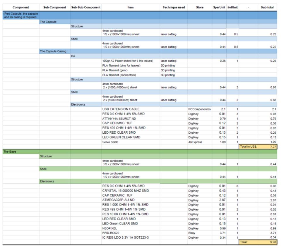
STEP 05 - PUTTING IT TOGETHER : THE ELECTRONICS for this step you need to source the following :
For the base, you will need :
- - 2 x "USB extension cable" - 60 cm long is fine;
- - 1 x "USB extension cable" - 200 cm long is recommended. It will be our power source;
- - "4-cables Wiring" - 150 cm long is fine;
For each casing, you will need :
- - 1 x "USB extension cable" - 60 cm long is fine;
- - "4-cables Wiring" - 50 cm long is fine;
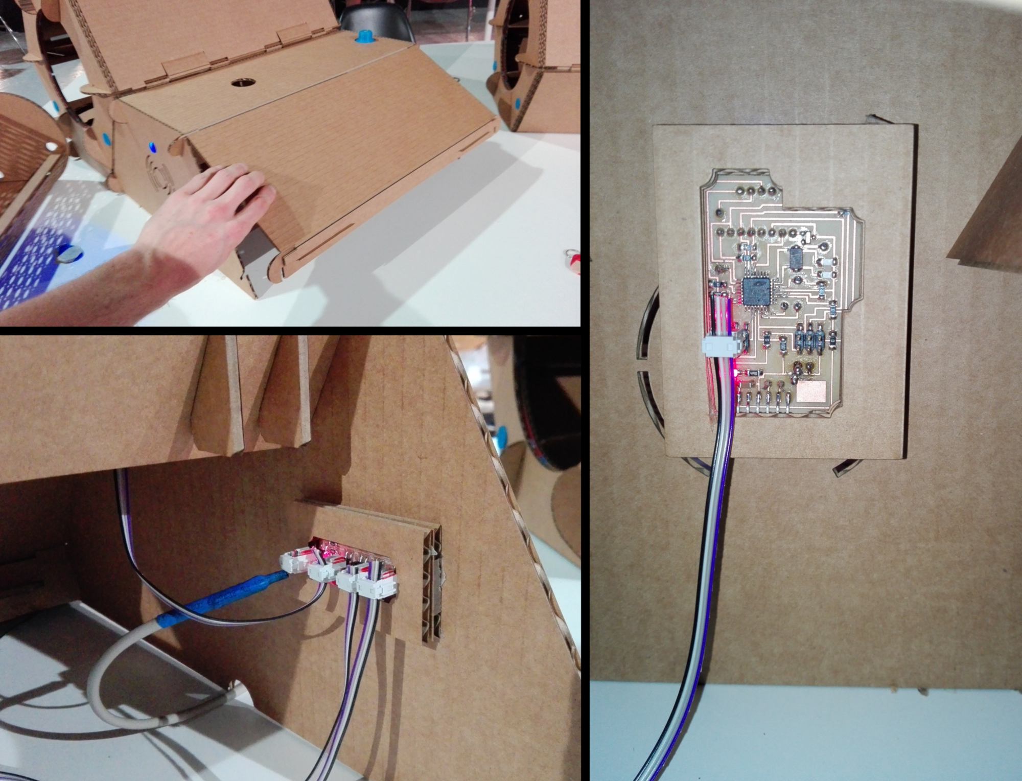
First put the PCBs in their cardboard casing. The two images below are there for reference, but do not either build the structure or stick the PCB into place yet, we will do so in the next step.
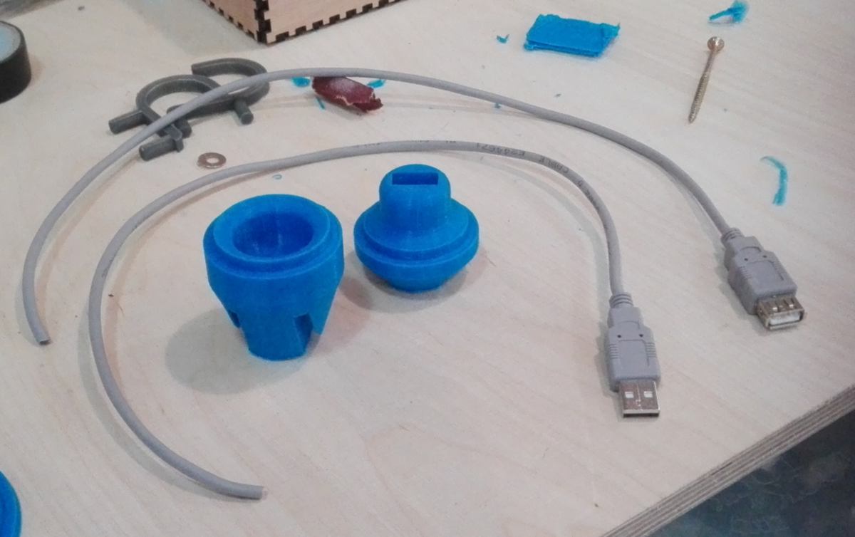
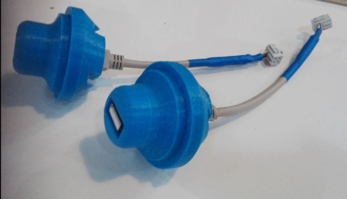
Cut each 60cm extension cords in half, then pass them through the pieces you printed earlier. You will see the female USB head (larger than the male one) fits in the female printed connector, and vice-versa. The USB header should fit very tightly. Then strip the wire and fit the four cables in a 2x2 female header as shown below :
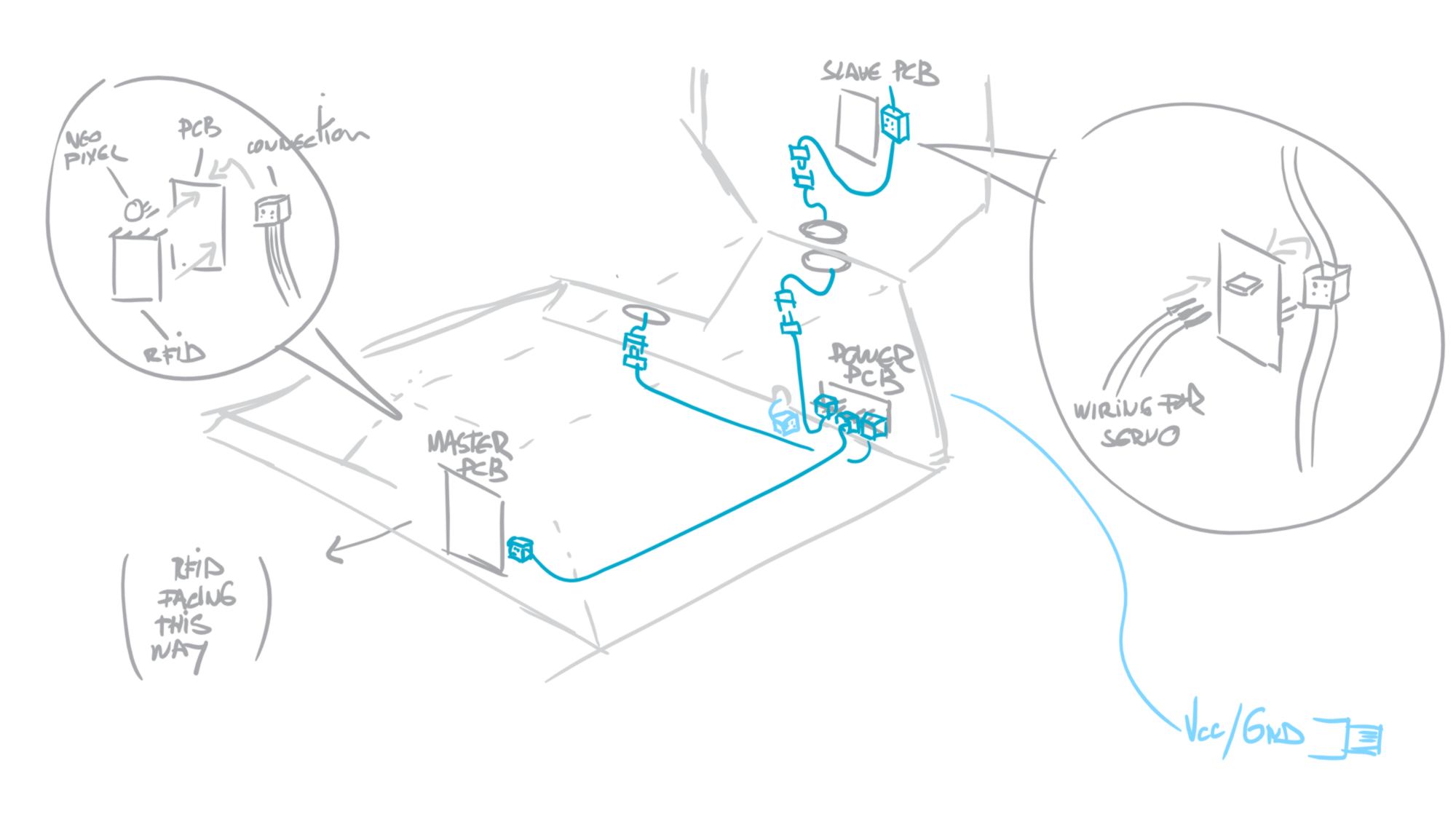
Now we can set all the wiring together and stick the PCBs into place. I show it in one single drawing below but it takes a bit of time to do it. By using the same type of female headers, you have to prepare all extra cables first (in dark blue in the drawing below), set the wires onto the PCBs, glue or tape (double-sided tape comes handy) the PCB casings to the structure and connect them together checking that the wiring is correct.
To ensure the VCC/GND/SDA/SCL are correctly connected, I used the same color for all wiring, VCC being red, GND being Black, SDA being Green and SCL being blue.
Then plug the servos to all your slave boards, following the wiring on the Eagle board file.
Finally cut the long 200cm extension cord by the end of the female header, strip it and plug VCC and GND using the same female header. This will be our power source, connected to a computer or a USB plug connected to a power point.
What you should have by now is a bunch of wires. This is time for a test. Power your power/connection board and swipe your RFID card to check the behavior of the whole system. Do the right servos spin for the right RFID card swiped? If so, we can put the rest of the structure together.
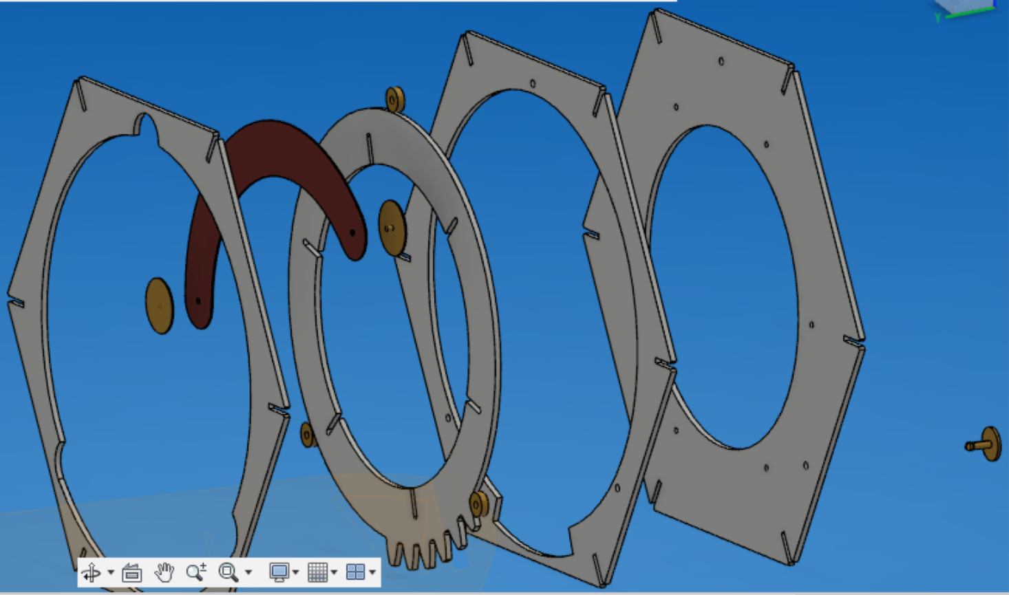
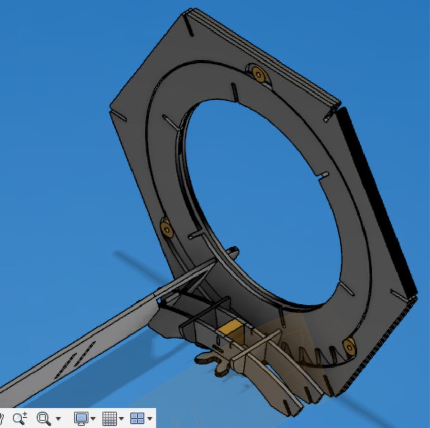
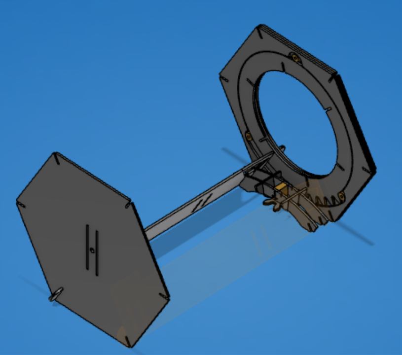
STEP 06 - PUTTING IT TOGETHER : THE STRUCTURE the assembly can be tricky. Specific parts have to be put together first, then the rest will follow. There are two delicate parts to put together :
- - the iris;
- - the servo, gear and the structure around it.
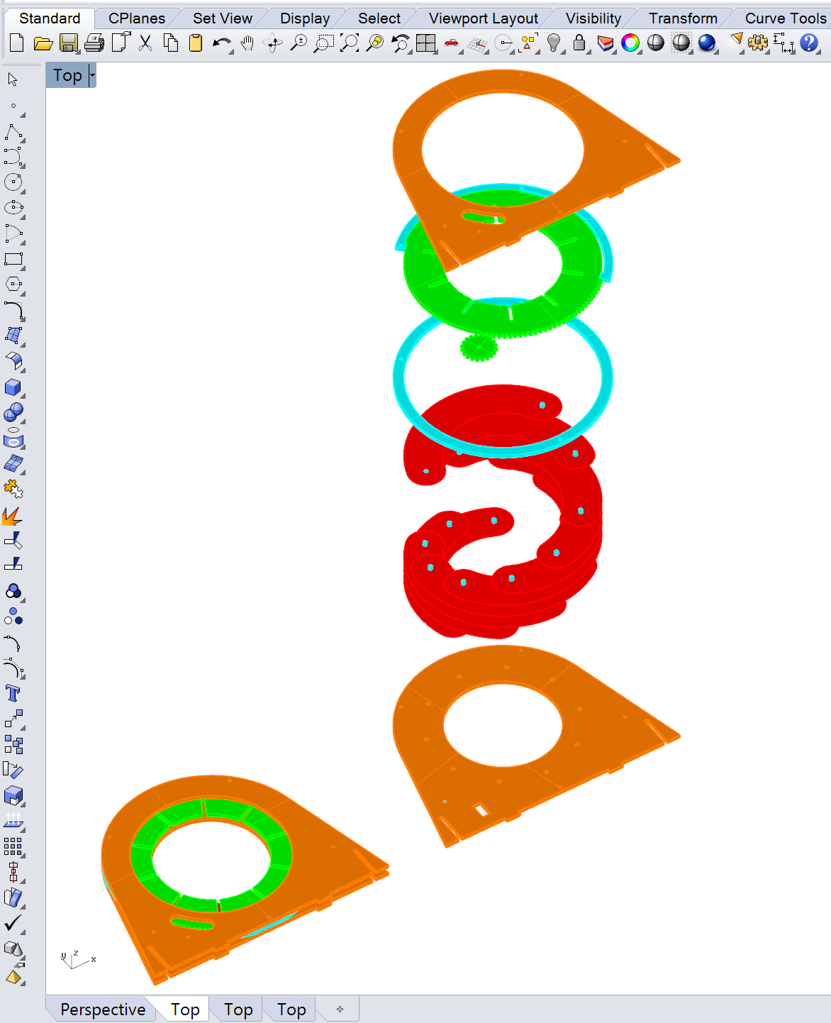
The put together the iris first:
As an extra reference, I add below a schematic from another iris which better illustrates how the leaves are set up :
In my case, I actually glued the pin to the paper leaves. It is not compulsory.
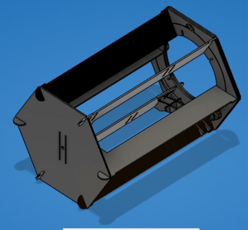
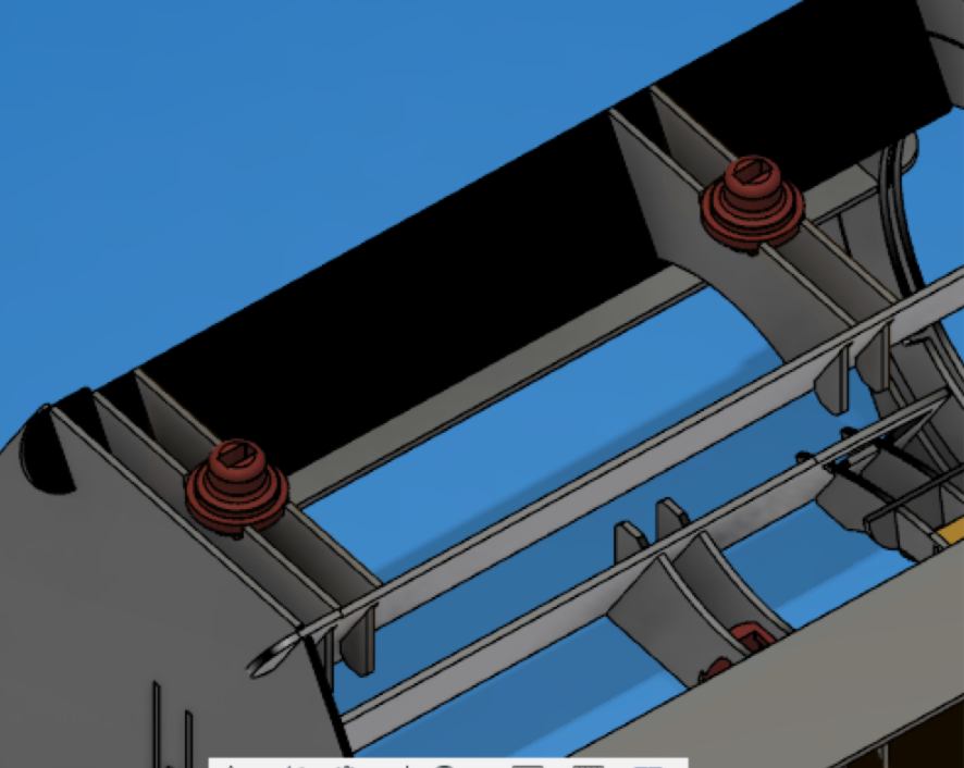
Then comes the servo/gear/structure related to it, and finally the rest of the structure :
You can then add the shell, aligning the holes with the 3d printed connections. The base is designed using the same system.
That is all! I think by now you should have it all working, but if not the case, contact me here : jbnatali@gmail.com. Thanks for the read, and let me know how it goes.
by JEAN-BAPTISTE NATALI jbnatali@gmail.com
 Fab Academy 2018
by JEAN-BAPTISTE NATALI
jbnatali@gmail.com
Fab Academy 2018
by JEAN-BAPTISTE NATALI
jbnatali@gmail.com