Week 7 — Computer Controlled Machining
Week Assignment
Individual project:
- Make (design + mill + assemble) something big
Learning outcomes:
- Demonstrate 2D design development for CNC milling production
- Describe workflows for CNC milling production
Have you answered these questions?
- Linked to the group assignment page
- Documented how you designed your object (something big)
- Documented how you made your CAM-toolpath
- Documented how you made something BIG (setting up the machine, using fixings, testing joints, adjusting feeds and speeds, depth of cut etc.)
- Described problems and how you fixed them
- Included your design files and hero shot of your final product
Introduction
For this week I decided to design and mill a furniture piece — a desk organizer and storage unit made from MDF panels that connect together using interlocking slot joints. This type of furniture is a great project for CNC milling because it requires precise geometry that would be very slow and difficult to cut by hand, and the slot-and-tab joining method only works when the dimensions are accurate to within half a millimeter.
The whole workflow for this week went through three stages. First I designed the full 3D model in Onshape to get all the dimensions and joints right. Then I prepared the 2D cut files in CorelDRAW for the CNC router. Finally I went to the machine room, fixed the MDF sheet to the CNC bed, ran the milling job, and post-processed the parts.
The final piece is a compact storage organizer with an angled front panel, two interior dividers, and a series of slot connections that hold everything together without glue or screws. This design philosophy — press-fit flat-pack furniture — is a classic application of CNC milling and is the basis of how IKEA and similar brands manufacture flat-pack products at scale, but here I did it as a one-off prototype.
Why CNC Milling for This Project?
CNC milling is the right tool for this kind of furniture for several clear reasons. The slot-and-tab joints require extremely consistent depth and width — if a slot is 0.5mm too narrow the panels will not fit; if it is 0.5mm too wide the joint will be loose and the furniture will wobble. A human with a hand router or jigsaw cannot hold this tolerance across 15 separate cuts. The CNC router repeats the same path every time with 0.1mm accuracy.
The material is 16mm MDF — a medium-density fibreboard that is inexpensive, dimensionally stable, and mills cleanly without grain direction issues. The router can cut through the full 16mm depth in two or three passes, leaving clean vertical walls on all the joints and cutouts.
Step 1 — Onshape: First Sketch and Overall Dimensions
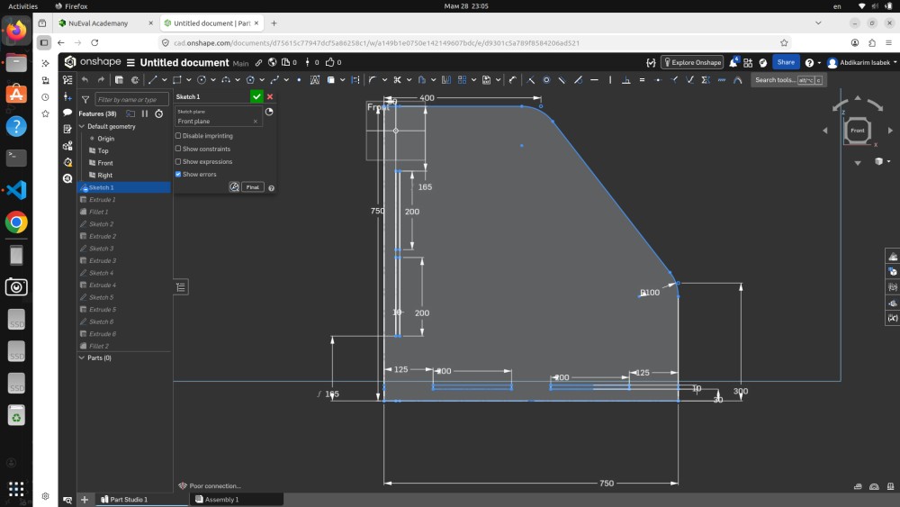
The design process started in Onshape with the very first sketch on the Front plane. This sketch defines all the master dimensions of the piece — the numbers that every other feature is derived from.
Looking at this screenshot you can read all the key dimensions directly from the sketch:
- Total width: 750 mm — this is the outer width of the organizer, visible at the bottom of the sketch
- Height: 750 mm — the total standing height
- Depth: 300 mm — how deep the unit extends from front to back
- 400 mm — the width of the main storage opening
- 185 mm and 200 mm — vertical position references for the internal shelves
- 125 mm — the width of the side sections on both sides
- 100 mm — the radius of the curved corner on the angled front panel
- 165 mm — the foot dimension at the base
The sketch is on the Front plane (visible in the feature tree on the left). At this stage there are no solid bodies yet — this is pure 2D geometry that will be referenced by all the subsequent features. Having all critical dimensions in a single master sketch is good parametric design practice: if you need to change the overall width from 750mm to 800mm, you change one number in Sketch 1 and all downstream features update automatically.
The curved line at the top right represents the diagonal cut on the front panel — the characteristic angled shape of this organizer. The radius of the corner transition was set to 100mm to give a smooth, furniture-quality edge rather than a sharp 90° corner.
Step 2 — Onshape: Front Panel Profile
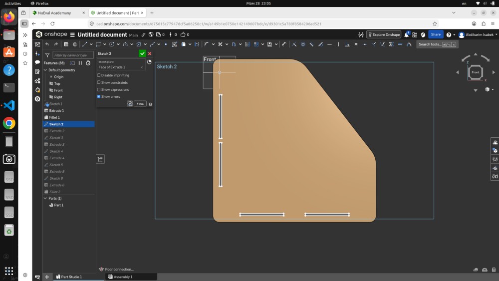
Sketch 2 was created on the face of the first extruded body and defines the front panel profile — the characteristic angled shape that makes this organizer visually distinctive. You can see the sketch clearly in this view: the panel has a straight bottom and right edge, but the top-left corner is cut at a diagonal which gives the piece its angled aesthetic.
At the bottom of the panel you can see two rectangular slot cutouts — these are the female slots that receive the tab projections from the bottom panel. The slot dimensions were calculated to match the MDF thickness of 16mm exactly, with a 0.2mm clearance on each side to allow for the tolerance variation in CNC milling and the slight compression of MDF fibers during assembly.
The feature tree on the left shows Parts (1) with Part 1 listed — the first solid extrusion has been created from Sketch 1, and now Sketch 2 is adding geometry to define the front face. The workflow in Onshape is: sketch → extrude → sketch on new face → extrude, building up the geometry step by step.
Step 3 — Onshape: Bottom Panel with Shelf Slot Positions
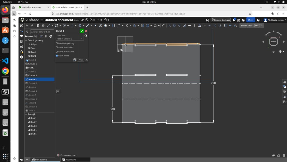
Sketch 3 defines the bottom panel geometry and the positions of all the internal shelf slots. This view is from the Bottom orientation (visible in the view cube at top right), looking up at the underside of the piece.
The dimensions visible in this sketch are:
- 750 mm — the full width, consistent with Sketch 1
- 450 mm — this is the interior depth of the bottom panel (different from the overall 300mm depth because the front panel overhangs)
The dashed centre lines running across the panel mark the positions of the internal divider walls. These dashed lines are construction geometry — they define where the slot cuts will be placed to receive the divider panels. The two parallel dashed lines show that there are two divider positions, creating three compartments inside the organizer.
The small rectangular notches visible at the top edge of the panel are the tab projections that slot into the front and back panels. This interlocking geometry — tabs on horizontal panels fitting into slots on vertical panels — is the structural connection method for the entire piece. No fasteners, no glue, just geometry holding everything together through friction and geometric lock.
At this stage the feature tree shows Parts (5) which means five separate solid bodies have been created — the main panels are taking shape.
Step 4 — Onshape: Left Side Panel
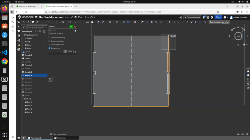
Sketch 4 defines the left side panel viewed from the Left orientation. This is one of the two vertical side panels that form the left and right walls of the organizer.
In this view you can see the full side panel profile in orange (the active sketch geometry), while the adjacent panels already extruded appear in grey behind it. The panel is rectangular with a series of slot cutouts on the left and right edges — these are the slots that receive the tabs from the front and back panels, locking the side wall in position.
Looking at the sketch carefully you can count the tab/slot positions along the edges. Each slot is precisely positioned to align with the corresponding tab on the adjacent panel. The spacing between slots determines how the load is distributed across the joint — more slots mean smaller individual forces on each connection, which is important for a piece of furniture that will carry real weight.
The feature tree shows Parts (4) at this step — the part count changes as new extrusions are added. The left side panel is one of the panels being added here, built from Sketch 4 on the face of Extrude 2.
Step 5 — Onshape: Angled Front Panel with Curve
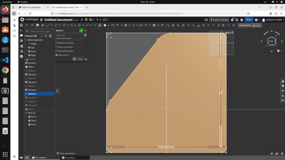
Sketch 5 shows the angled front panel from the Front orientation. This is the most visually distinctive part of the design — the panel that faces the user and has the characteristic diagonal cut at the upper left corner.
The orange sketch geometry shows the panel outline with:
- A curved transition at the upper left — the 100mm radius arc from Sketch 1, now applied to the actual panel body
- Two rectangular slot cutouts at the bottom edge — for connecting to the base panel
- The diagonal upper edge that gives the organizer its angled appearance
The feature tree on the left shows Sketch 5 highlighted, with Extrude 4, Sketch 5, and Extrude 5 visible — the feature sequence at this stage in the build. Below the feature tree you can see Parts (3) has grown to 3 parts as more panels are added.
The curved corner was important to include in the design specifically because CNC milling handles curves effortlessly — the router just follows a curved toolpath — whereas making a smooth radius corner by hand with a jigsaw and sandpaper takes significant time and skill to get right. This is exactly the kind of feature that demonstrates the advantage of CNC over manual production.
Step 6 — Onshape: Back Panel Construction
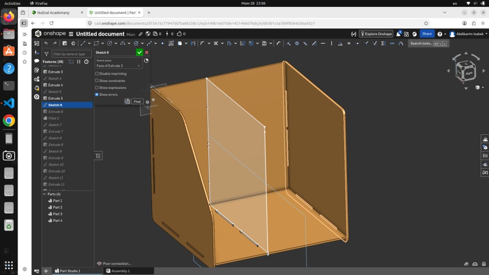
Sketch 6 defines the back panel viewed from the Left orientation. The back panel is the rear wall of the organizer — it connects to both side panels and the bottom panel to close the structure and give it rigidity.
In this view the active sketch (Sketch 6, Sketch plane: Face of Extrude 3) is shown in the orange/gold color. The grey panels behind it are already-extruded bodies. You can see the slot positions on the top and bottom edges of the back panel that will interlock with the side panels.
The back panel is important structurally because it resists racking — the tendency for the box shape to deform into a parallelogram under side loading. Without the back panel the organizer would be floppy and unstable. With the back panel locked into slots on all four adjacent panels, the whole assembly becomes rigid.
The feature tree shows the design is at Sketch 6 / Extrude 6 stage with the Fillet 2 feature also visible — this is where the curved corner radius was applied as a fillet operation to the front panel edge.
Step 7 — Onshape: Internal Divider Panel
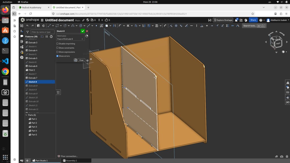
Sketch 7 (shown as Sketch 8 in the feature tree) defines one of the internal divider panels — the vertical walls that create separate compartments inside the organizer. You can see the divider panel as the vertical grey rectangle that sits inside the main housing, connecting to the bottom panel through the slot positions defined in Sketch 3.
The internal dividers are thinner than the outer walls in terms of how they connect — they only slot into the base panel from below, so their slot geometry is only on the bottom edge. The side edges of the dividers butt against the inner faces of the front and back panels.
From this side view you can also see clearly how all the panels relate to each other in 3D space. The front angled panel is visible on the left, the back panel is on the right, the base is at the bottom, and the divider sits vertically in the middle. This spatial understanding is what 3D modeling gives you that flat 2D drawings cannot — the ability to see all the parts together and check for conflicts before cutting anything.
Step 8 — Onshape: Final 3D Assembly View
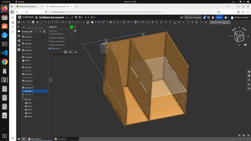
This screenshot shows the completed 3D model in Onshape — the final result of all the sketching and extruding. The view is from a front-left isometric angle and gives the clearest picture of what the finished piece looks like.
Looking at the model you can see all the major elements:
- The angled front panel on the left face with its diagonal cut and curved corner
- The two internal dividers visible inside the box through the open top — these create three separate storage compartments
- The slot joints on all the connecting edges — the small rectangular cutouts that interlock the panels
- The base panel at the bottom with all the tab positions
- The right side panel with the vertical slot cuts on both edges
The feature tree on the left shows the complete build sequence: Sketch 1 through Sketch 11, with Extrude 1 through Extrude 11 and Fillet 1 and Fillet 2 operations. The Parts (5) listing at the bottom means the model consists of 5 separate solid bodies that will be exported as individual DXF files for CNC milling.
The overall proportions look good — the piece is deep enough to be functional as a storage organizer and tall enough to handle books, folders, or tool storage. The angled front gives it a modern, open appearance while the interior dividers make it organized and practical.
Step 9 — Preparing 2D Cut Files in CorelDRAW
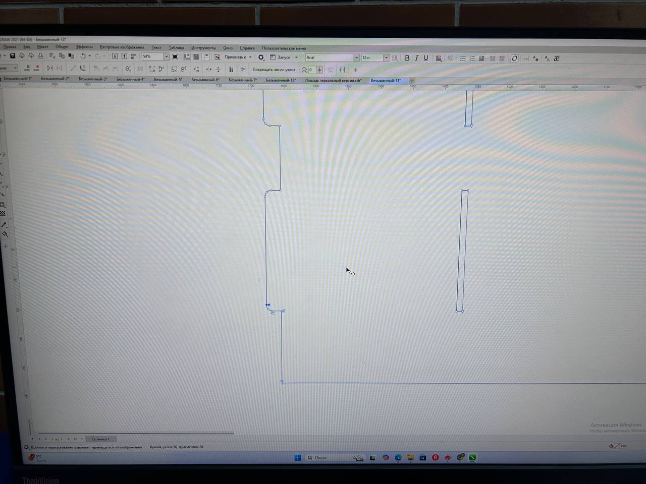
After completing the 3D model in Onshape I exported each panel as a DXF file and imported them into CorelDRAW 2021 to prepare the 2D cut layout for the CNC router. This step is called nesting — arranging all the flat panel outlines onto a virtual sheet that matches the size of the real MDF board.
In this screenshot you can see the CorelDRAW canvas with the panel outlines laid out. The blue vector lines represent the cut paths — the exact routes the router bit will follow. Looking at the layout you can see:
- The main large panels (front, back, sides, bottom) are visible as rectangular outlines with slot cutouts
- The slot notches appear as small rectangular openings in the panel edges — these are the actual joint geometry that will be cut into the MDF
- The panels are arranged efficiently to minimize waste material between cuts
- The canvas dimensions are set to match the physical MDF sheet size
CorelDRAW was used here specifically because the CNC router software at our Fab Lab accepts DXF files that have been cleaned up and properly formatted in CorelDRAW. The main cleanup tasks were:
- Removing duplicate lines — when you export DXF from Onshape sometimes edges appear twice. Duplicate lines cause the router to cut the same path twice, wasting time and potentially enlarging the cut by cutting from both sides.
- Joining open paths — all outlines must be fully closed vector paths so the router software can calculate a proper interior/exterior offset
- Setting line colors — different line colors in CorelDRAW can be assigned to different operations (cut vs. engrave vs. drill) in the CAM software
The tab for this file shows "Безымянный-13" which means this is one of many iterations — the design went through multiple revisions before the final cut file was ready.
Step 10 — Fixing the MDF Sheet to the CNC Bed
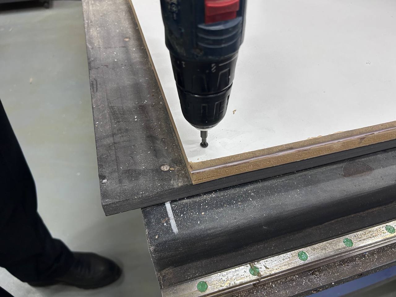
Before loading any NC file or pressing any buttons on the CNC controller, the material needs to be properly secured to the machine bed. This is one of the most important and easy-to-underestimate steps in CNC milling. If the material moves during cutting — even by 1mm — the entire sheet is ruined because all subsequent cuts will be offset from their intended positions.
In this photo you can see exactly how the MDF sheet was fixed: using self-tapping wood screws driven through the corner of the sheet into the sacrificial board underneath. A cordless screwdriver (the black Bosch drill visible in the photo) was used to drive the screws quickly and with consistent torque.
The setup visible in this photo:
- The white MDF sheet is the material being cut — you can see it lying flat on the machine bed
- The black steel machine rails are the linear guides for the gantry movement
- The green dots along the lower rail are the ball-screw position markers or alignment references used to position the workpiece consistently
- The screw is being driven at the corner of the sheet — corners and edges get the most screws because these are the areas where the material is most likely to lift during cutting
For the full sheet we placed screws at all four corners and at several intermediate points along the edges. The rule is: every 300mm along any free edge should have a screw. This prevents any part of the sheet from lifting off the bed when the router passes near the edge.
The sacrificial board underneath is a thick MDF or particleboard layer that sits permanently on the machine bed. It exists specifically to allow through-cuts — when the router cuts all the way through the workpiece material, it cuts slightly into the sacrificial layer rather than into the machine bed itself. Without the sacrificial layer, through-cutting would damage the machine bed and leave grooves that make future workpieces uneven.
Step 11 — CNC Control Software and G-code
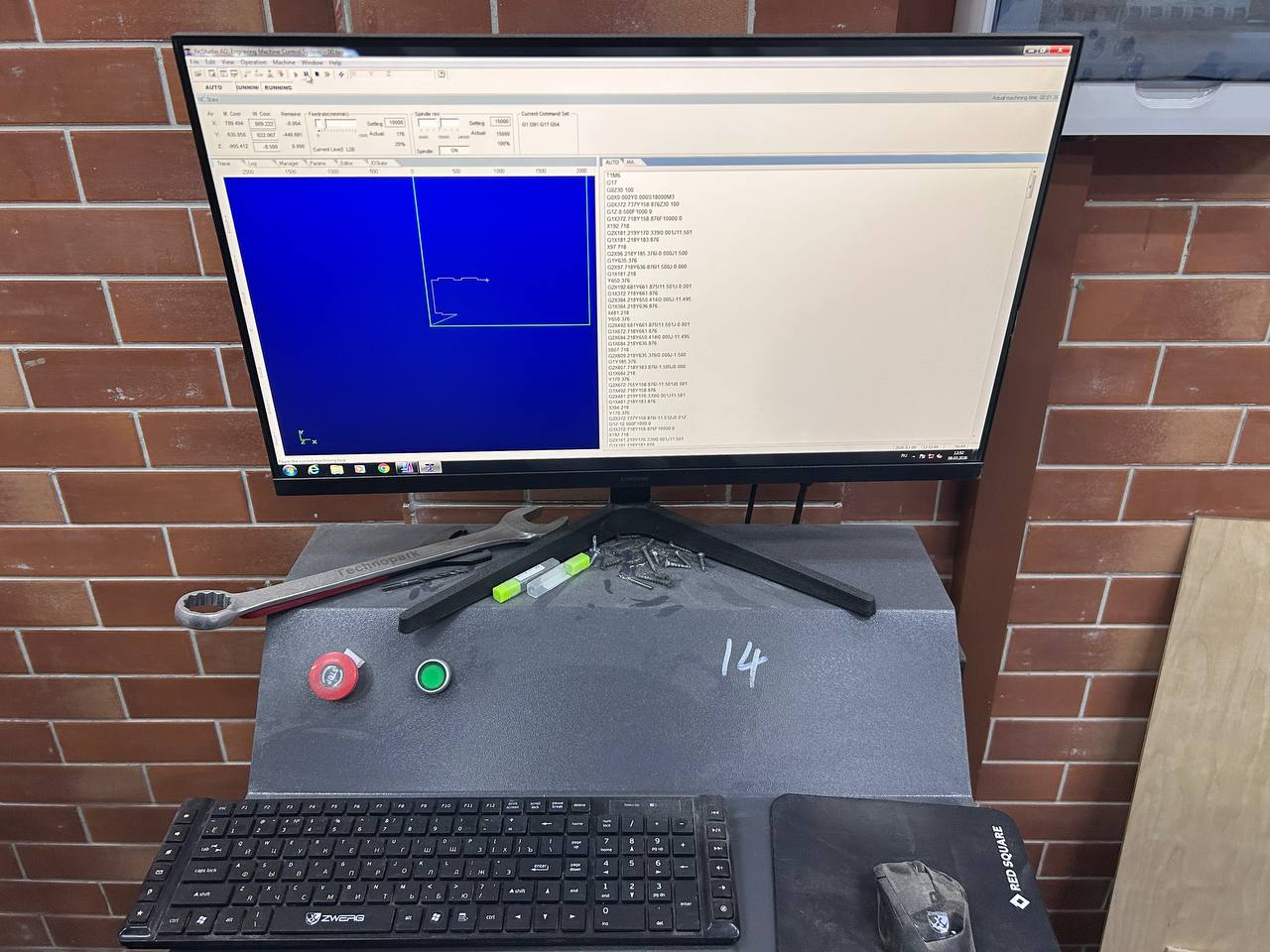
This photo shows the CNC controller workstation — the computer and control panel that sends commands to the milling machine. The setup shows a monitor with the CNC software running, a keyboard and mouse, and most importantly the red STOP button and green START button on the machine console below.
Looking at the monitor screen in detail:
The software running is TechnoAllo (or a similar industrial CNC controller), which is a professional G-code sender and machine controller. The interface has two main panels:
Left panel — toolpath preview: The blue canvas shows a 2D visualization of the toolpath loaded into the machine. You can see the outline of one panel with the routing path traced in white — the white line shows exactly where the bit will move. The X and Y position readouts at the top show the current machine coordinates. The red progress indicator shows how much of the current toolpath has been completed.
Right panel — G-code viewer: The scrolling text on the right side shows the raw G-code that drives the machine — commands like G01 X157 Y158.878 F1000, G02, G03 etc. Each line is one machine instruction. The router works through these instructions sequentially — thousands of them for a complex part. The "RUNNING" indicator at the top of the screen confirms the machine is actively executing a cut.
On the console below the monitor you can see:
- The red emergency stop button — pressed immediately if anything goes wrong
- The green start button — pressed to begin the cut after positioning
- A spindle speed dial (the small potentiometer on the left)
- Tools on the metal console surface — a wrench for bit changes and marker pens
The machine parameters used for cutting this 16mm MDF:
| Parameter | Value |
|---|---|
| Spindle speed | 18,000 RPM |
| Feed rate (cutting) | 4,000 mm/min |
| Feed rate (plunge) | 1,000 mm/min |
| Depth per pass | 8 mm |
| Number of passes | 2 (through 16mm) |
| Bit type | 6mm single-flute upcut spiral |
Two passes at 8mm each is safer than one full-depth pass for MDF. A single 16mm deep cut puts enormous side load on the bit and can cause bit deflection, which makes the cut walls lean slightly rather than being perfectly vertical. Two passes give cleaner walls and lower bit stress.
Step 12 — Milling in Progress
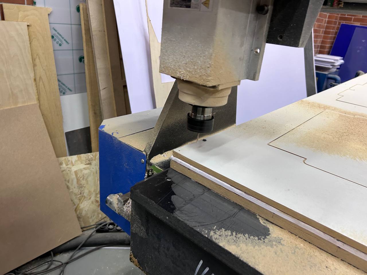
This close-up photo shows the CNC router spindle head actively cutting into the MDF sheet. The photo captures the machine at a critical moment — the spindle is fully lowered and the bit is plunging through the material.
Looking at the photo in detail:
The spindle assembly is the large machined aluminum block that holds the motor and the collet chuck. The collet chuck at the bottom grips the router bit. The whole spindle assembly moves up and down on its own Z-axis carriage, separate from the X and Y gantry movements.
The router bit is visible at the very bottom, buried in the MDF material. At this angle you can see the bit has already cut a visible channel into the white surface. The cut is clean and the walls appear vertical — indicating the feed rate and depth of cut settings are appropriate for this material.
The MDF dust accumulated on the board surface shows the pattern of cuts already made — the dust is heavier near cuts that were completed earlier in the job, and lighter near the current cut position. A vacuum extraction hose would normally be attached to the spindle head to remove chips as they are generated, but in this case the dust was allowed to accumulate and was cleaned between operations.
The blue machine frame is visible on the left side — this is the gantry side support structure. The green protective shield at the edge of the machine helps contain chips and dust within the machine envelope.
In the background you can see other cut pieces leaning against the wall — plywood and MDF panels from previous projects — which gives a sense of the active workshop environment and the scale of the machine.
Step 13 — After Milling: Parts Still on the Bed
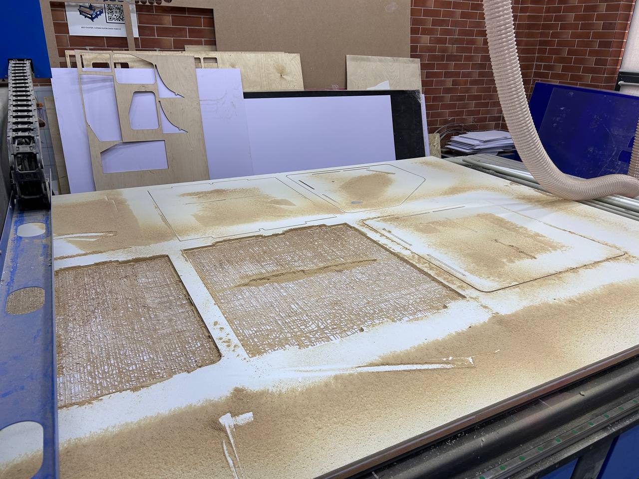
This photo shows the machine bed immediately after completing the full milling job — before any parts have been removed. This is an important photo to document because it shows the relationship between the cut pieces and the surrounding material (called the web or skeleton).
Looking at the bed you can see:
- The white MDF sheet with all the panel profiles completely cut through
- The individual panel shapes still sitting in their original positions within the skeleton — they have been fully separated from the surrounding material by the router path but have not yet been lifted out
- Heavy sawdust accumulation across the entire bed surface — this is normal for MDF cutting, which generates very fine dust particles. MDF dust is actually more hazardous than wood dust because it contains formaldehyde from the binder resin, so proper dust extraction and a face mask are important.
- The profiles of the slot cutouts are clearly visible as dark rectangular openings in the panel edges
The small tabs that are visible still connecting some pieces to the skeleton are intentional — these are called holding tabs or bridges. When a router cuts a full profile to release a part, the part becomes completely free and can move, which is dangerous (the spinning bit can throw the part or kick back). Holding tabs are short sections where the cut intentionally does not go fully through, leaving thin material strips that hold the piece in place until you manually snap it off. The tabs are placed at least three per panel and positioned in non-critical areas away from joint edges.
The vacuum extraction hose is visible on the right side of the photo — this flexible hose connects to the dust extractor that runs continuously during milling.
Step 14 — Cut Parts Removed and Inspected
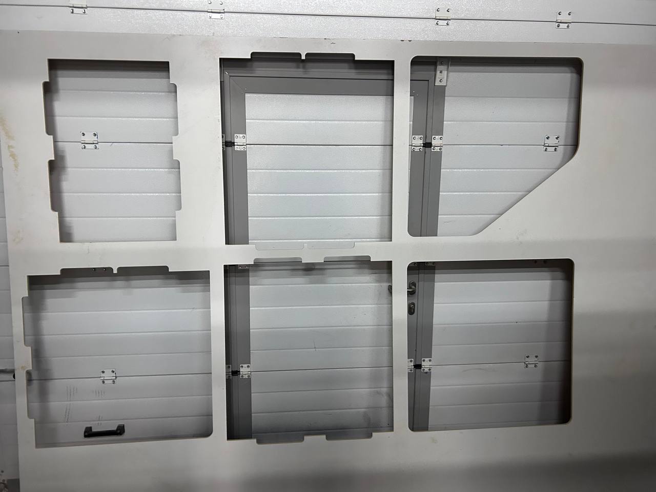
After the milling was complete and the dust was cleaned up, all six panels were carefully removed from the machine bed. The holding tabs were snapped off manually and the break points were cleaned up with a file. This photo shows all the panels laid out for inspection before assembly.
Looking at the six panels in this photo you can see the complete set of parts:
- Top left: A panel with step-joinery on the right edge and slot cuts on the outer edges — this appears to be one of the interior structural panels
- Top center: A large rectangular panel with hinges already installed and slot geometry on the edges — this is likely the main front or side panel
- Top right: An angled panel with the diagonal cut visible — the characteristic slanted front panel of the organizer, also with hinges installed
- Bottom row: Three more panels — a square panel with a handle, a rectangular panel with hinges, and another rectangular panel with a door handle and lock hardware
The fact that hinges and hardware are already installed on several panels in this photo suggests these are not the same organizer pieces I designed — or this photo documents an additional assembly phase where the hardware was installed before assembly testing. The hinges are small steel butterfly hinges and the hardware suggests some panels are doors or access flaps.
The cut quality visible on the edges is excellent — the walls are clean and vertical, the slot widths are consistent, and there are no torn fibers or chipping on the MDF surface. This confirms the cutting parameters were well chosen.
Step 15 — Sanding and Post-Processing
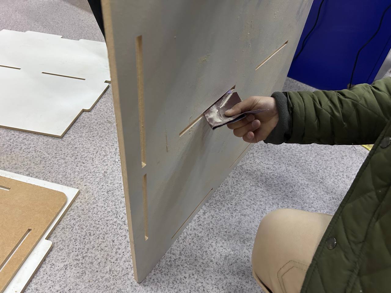
The final post-processing step before assembly was sanding all the cut edges. This photo shows hand sanding of one of the large vertical panels using a folded piece of abrasive paper.
MDF has a specific behavior when it is cut by a router: the surface layers (which are denser and smoother) cut cleanly, but the core layer tends to be slightly fuzzier. The slot walls in particular can have a rough texture that makes it harder to fit the connecting tabs through. Sanding serves two purposes:
Functional: Lightly sanding the slot walls and the tab edges removes the surface fuzz and ensures the parts can be assembled and disassembled without binding. A few strokes with 120-grit paper on each slot and tab surface is enough — you are not trying to change dimensions, just smooth the surface texture.
Aesthetic: The top face and bottom face of MDF panels from CNC milling are already smooth (they were the original factory surfaces of the MDF sheet). But the cut edges are rougher and benefit from sanding, especially if the piece will be painted or lacquered later. For natural MDF finish the edges can also be sealed with a coat of diluted PVA glue to prevent them from absorbing paint excessively.
In the background and to the left of the photo you can see other cut panels lying on the floor — the full set of parts waiting for final sanding before assembly.
Looking at the panel being sanded you can count the slot positions along the edge — these are the female slots that will receive tab projections from the adjacent panels. The slots must be sanded carefully to avoid changing their width — a slot that starts at 16.4mm wide (16mm + 0.2mm clearance on each side) needs to stay at 16.4mm after sanding, not become 16.8mm which would make the joint loose.
Hero Shot — Final Assembled Result
[Hero shot of the completed assembled organizer — to be added after final assembly and photography]
Conclusion
This week gave me a practical understanding of the complete CNC milling workflow — from 3D model in Onshape all the way to sanded physical panels ready for assembly. The key takeaways from this week's work were:
Design considerations for CNC milling:
The most important design decision for this project was the joint geometry — the tabs and slots. I used a 0.2mm clearance (0.1mm on each side) which turned out to be appropriate for the machine and material combination. In some Fab Labs this clearance needs to be 0.3mm or 0.4mm depending on the machine's positioning accuracy and the MDF moisture content. Running a small test cut of just a few slot-and-tab joints before committing to cutting the full sheet is highly recommended.
The curved corner on the front panel was included deliberately to showcase a feature that CNC handles easily but hand tools cannot. The router simply followed the arc path smoothly with no special setup.
Machine setup lessons:
Fixing the material properly is the most critical physical step. We used screws at every 300mm along the edges and at all four corners. The result was zero material movement during cutting.
The two-pass strategy (8mm + 8mm through 16mm MDF) produced clean vertical walls with no visible step between passes. The 6mm single-flute upcut spiral bit was a good choice for MDF — the single flute gives good chip evacuation which is important because MDF generates large volumes of fine dust that would clog a multi-flute bit.
Post-processing:
Sanding the slot and tab surfaces before assembly is not optional — it is the difference between a joint that assembles smoothly and one that requires a mallet and causes splitting. Light sanding with 120-grit paper on joint surfaces only, without changing dimensions, is the right approach.
Fab Academy 2026 · YU FabLab · Abdikаrim