Week 5 — 3D Scanning and Printing
Week Assignment
Individual assignment:
- Design and 3D print an object (small, few cm³, limited by printer time) that could not be easily made subtractively
- 3D scan an object (and optionally print it)
Learning outcomes:
- Identify the advantages and limitations of 3D printing
- Apply design methods and production processes to show your understanding of 3D printing
- Demonstrate how scanning technology can be used to digitize objects
Have you answered these questions?
- Linked to the group assignment page
- Explained what you learned from testing the 3D printers
- Documented how you designed and 3D printed your object and explained why it could not be easily made subtractively
- Documented how you scanned an object
- Included your original design files for 3D printing
- Included your hero shots
Introduction
For this week's assignment I decided to take a different approach compared to printing a simple test object. Instead of designing something new from scratch just for the sake of printing, I used this week as an opportunity to physically produce a real component for my final project — the planetary gear reducer that I designed in Onshape during Week 2.
This was a meaningful choice for several reasons. The gear reducer is a genuinely complex mechanical assembly with interlocking parts, internal tooth profiles, and tight dimensional tolerances. It is a perfect example of an object that cannot be made subtractively — the internal gear teeth of the ring gear, the planet carrier geometry, and the way the housing encloses the gears from all sides would be impossible to produce on a conventional mill or lathe without multi-axis CNC equipment. 3D printing is the right manufacturing method for this kind of part, especially for a prototype.
The full workflow for this week was:
- Take the completed 3D model from Onshape (designed in Week 2)
- Export all parts as STL files
- Slice the parts in Bambu Studio for the Bambu Lab P1S printer
- Print all parts
- Assemble the reducer — press gears together and install brass heat-set inserts
- Close the housing with screws
- Test the reducer by connecting it to the Nema 17 stepper motor and running it with a TB6600 driver and ESP8266
Why This Object Cannot Be Made Subtractively
Before going into the production process, it is worth explaining in detail why this reducer assembly is a good example of additive manufacturing's advantages over subtractive methods.
Internal gear teeth: The ring gear has teeth on the inside of a cylindrical cavity. To machine internal gear teeth subtractively you would need a specialized gear shaper or broaching machine — neither of which is available in a standard Fab Lab. Even with a CNC mill you cannot reach inside a closed cavity to cut teeth pointing inward.
Planetary carrier geometry: The planet carrier has a complex shape with multiple bearing pockets, radial arms, and through-holes that intersect at different angles. Machining this from solid material would require multiple setups and fixture changes on a 5-axis machine.
Housing with integrated features: The reducer housing combines a cylindrical gear cavity, mounting ears, bolt bosses, bearing seats, and snap ring grooves all in one part. Each feature alone is machinable, but achieving them all in a single part with the correct wall thicknesses requires either multiple operations or a dedicated casting mold — neither practical for a one-off prototype.
Assembly without fasteners: 3D printing allowed me to design parts that snap together or press-fit, reducing the number of fasteners needed and speeding up assembly.
Step 1 — Final 3D Model in Onshape Assembly
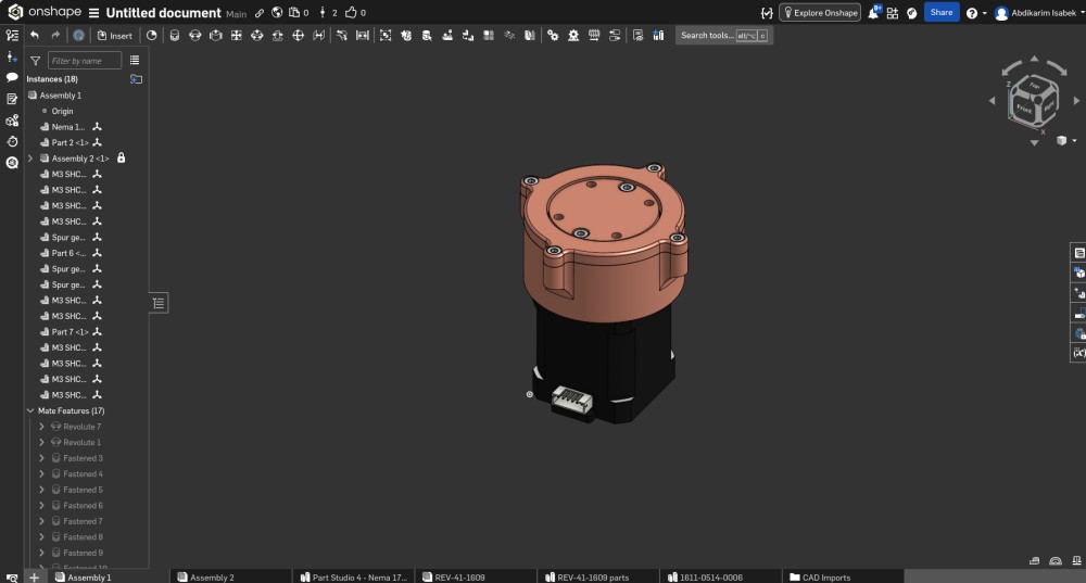
This screenshot shows the Onshape Assembly environment with the fully completed planetary gear reducer model. This is the same model I designed during Week 2 but now shown in the Assembly workspace where all individual parts have been brought together and constrained with mates.
Looking at the left panel you can see the full instance list of the assembly — 18 total instances including:
- Nema 1... — the imported Nema 17 stepper motor STEP model used as the reference base
- Part 2 <1> — the main reducer housing body
- Assembly 2 <1> — a sub-assembly (the planet carrier with its gears)
- Multiple M3 SHC... instances — M3 socket head cap screws for all the fastener positions
- Spur ge... instances — the spur gear parts (sun gear, planet gears)
- Part 6 <...> and Part 7 <1> — the output cover and planet carrier
- Mate Features (17) — seventeen constraint relationships defining how all parts connect
The 3D view shows the reducer from a front-isometric angle. The copper-tone housing is clearly visible with the circular top flange and the four side mounting ears. The Nema 17 motor is the dark black body at the bottom. The motor connector cable is shown at the front bottom of the motor body. Looking at the top of the housing you can see the six bolt positions and the output shaft hole in the center.
The bottom tab bar of the browser shows the multiple workspaces in this Onshape document: Assembly 1, Assembly 2, Part Studio 4 - Nema 17, REV-41-1609, REV-41-1609 parts, 1611-0514-0006, and CAD Imports — showing the full complexity of the file structure with imported components.
Before moving to printing, I exported each individual part as an STL file at high resolution (0.1mm chord tolerance) to ensure the gear teeth were represented with sufficient polygon density. The gear tooth profiles are curved involute surfaces and low-resolution STL export would make the teeth faceted and unusable.
Step 2 — Slicing in Bambu Studio
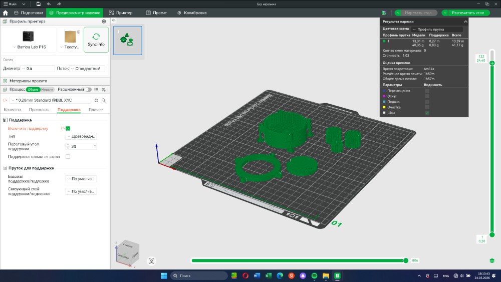
After exporting all the STL files from Onshape I imported them into Bambu Studio — the slicing software for the Bambu Lab P1S printer available in our Fab Lab. This screenshot shows the complete slice preview with all the reducer parts arranged on the build plate.
Looking at the build plate you can see all the parts laid out in green:
- The main housing body — the largest part, the cylindrical housing with the ring gear teeth on the inside and the mounting ears on the sides
- The output cover — the circular disc with the bearing seat
- The planet carrier — the cage that holds the planet gears
- Multiple gear parts — the sun gear and planet gears
- Small fastener-related parts if any
The green color indicates these are the model surfaces. The slightly darker green structures underneath and around some parts are the support structures — automatically generated scaffolding that holds overhanging features during printing. The support settings visible in the left panel show:
- Support enabled: On (blue toggle)
- Type: Tree-type supports — the tree-shaped supports that use less material and are easier to remove than solid block supports
- Support threshold angle: 30° — angles steeper than 30° from vertical get supports
- Support only from build plate — unchecked, meaning supports can grow from part surfaces too
On the right side of the screen the slice results panel shows:
- Filament used: 13.59 m model + 0.27 m support = total 13.86 m
- Weight: 40.35 g model + 0.83 g support = 41.17 g total
- Material changes: 0 — single material print, no filament swaps needed
- Cost: 1.03
- Preparation time: 6m14s
- Estimated print time: 1h50m
- Total print time: 1h57m
The printer profile shows Bambu Lab P1S with 0.4mm nozzle diameter, standard flow, and 0.20mm Standard @BBL X1C layer profile. The 0.20mm layer height is a good balance between print speed and detail resolution for mechanical parts — fine enough to capture the gear tooth geometry but fast enough to complete in under two hours.
One important setting I considered was wall count and infill for the gear parts. Gears need to be strong because they transmit torque and experience repeated stress. I set the walls to at least 4 perimeters and used 40% gyroid infill for the main housing and gear parts to ensure they would not crack or deform under load.
Step 3 — Printed Parts and First Assembly
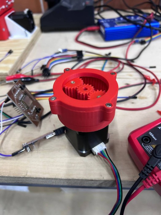
This photo shows the reducer after the first assembly test — before installing the top cover. The parts came off the Bambu Lab P1S printer in red PLA filament and were cleaned up by removing the support structures. This view is very satisfying because you can see directly into the reducer mechanism before the cover goes on.
Looking at the photo in detail:
The red PLA housing is mounted on top of the black Nema 17 stepper motor. The circular housing body with its side mounting ears is clearly visible. The housing printed cleanly with good layer adhesion and the internal ring gear teeth printed with correct geometry.
Inside the housing you can see the three planet gears — two larger gears (20 teeth) and one smaller gear (15 teeth) — all sitting on their respective shaft positions on the planet carrier. Most importantly, the gears are visibly meshing with each other and with the sun gear in the center. This was the moment of validation — the gear tooth geometry from the Onshape model transferred correctly through STL export, slicing, and printing, and the parts physically fit together with proper tooth engagement and no binding.
The tolerances in 3D printed gear assemblies are always a concern. If the clearance between meshing teeth is too tight the gears will bind and the motor will stall. If it is too loose there will be excessive backlash. For these gears I designed a 0.15mm clearance on each tooth flank in the Onshape model, and after printing the gears rotated smoothly with minimal play.
In the background of the photo you can see the lab workbench environment — wires, components, electronics equipment — which gives a good sense of the real working context. On the left side there is what looks like a custom PCB board, and on the right there is a multimeter, all part of the testing setup that would come later.
Step 4 — Installing Brass Heat-Set Inserts
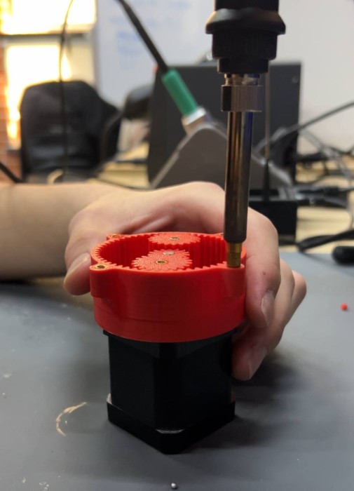
This photo shows one of the most important assembly steps — installing brass heat-set inserts (also called thermoplastic inserts or heat-press nuts) into the 3D printed housing. These are small brass cylinders with internal M3 threads that are pressed into the plastic while hot using a soldering iron. As they cool down they form a very strong mechanical bond with the surrounding plastic.
You can see in the photo that the housing is held steady while a soldering iron with a brass tip presses the insert straight down into the prepared hole. The tip is specifically shaped for heat-set insert installation — a flat face that sits on top of the insert and applies even pressure while the heat transfers through the brass body and melts the surrounding PLA just enough for the insert to sink flush with the surface.
Why use heat-set inserts instead of just screwing into plastic directly?
When you screw a metal bolt directly into a 3D printed plastic hole the threads are formed in the plastic itself. This works for a few assembly/disassembly cycles but the plastic threads wear out quickly — especially if the part needs to be opened and closed multiple times for maintenance or adjustment. Plastic threads can also strip under high clamping force.
Brass heat-set inserts solve this completely. The brass has standard M3 threads that are as strong as any steel bolt can engage with. The reducer housing can be opened and reassembled many times without any thread wear. For a robotics project where the gearbox might need to be serviced or modified, this is the right approach.
For this housing I installed inserts at:
- The six output flange holes around the top face — for the M3 bolts that hold the cover plate
- The four side mounting ear holes — for attaching the reducer to the manipulator arm structure
The installation process needs to be done carefully. If the iron is too hot or you press too fast the insert can tilt or go in crooked, which will cause the bolt to misalign. I set the iron to about 200°C and pressed each insert slowly and steadily, letting the heat do the work rather than forcing it in.
Step 5 — Fully Assembled Reducer
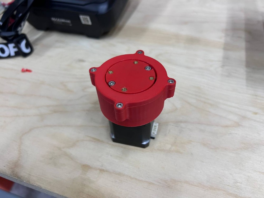
This photo shows the reducer fully assembled with the top cover installed and all screws tightened. This is the completed physical version of the digital model from Week 2 — everything that was designed in Onshape is now a real object sitting on the workbench.
Looking at the top face of the reducer you can clearly count six M3 socket head cap screws arranged in a circle on the output flange. These screws thread into the brass heat-set inserts that were installed in the previous step, clamping the circular cover plate firmly onto the housing body. The brass inserts are slightly visible as the gold-colored rings around each screw hole, which is a sign that the inserts are properly seated flush with the surface.
The side mounting ears are clearly visible on both sides of the housing — these are the lateral tabs with holes for attaching the reducer to the arm structure. You can also see two screws on the visible ear in this photo.
The Nema 17 stepper motor is the black square body at the bottom. The motor connector cable is visible on the right side. The motor connects to the reducer via its 5mm output shaft which slots into the sun gear bore inside the housing.
The overall impression of the assembly is compact and robust. The red PLA material makes all the parts visually clear and the print quality from the Bambu Lab P1S is excellent — smooth surfaces, sharp edges, and no layer delamination visible anywhere. The total height of the complete assembly (motor plus reducer) is approximately 80mm and the housing diameter is about 70mm.
One thing I noticed after assembling — the fit between the cover plate and the housing bore was very clean. The 0.2mm clearance I designed between the cover OD and the housing bore ID produced a light press-fit that stays in place without extra fasteners but can be removed by hand when needed.
Step 6 — Testing the Reducer
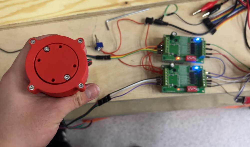
This photo shows the final test setup — the complete assembled reducer held up in front of the electronics control panel. This is the hero shot of the week because it brings together all the work: the 3D printed reducer, the stepper motor, the driver electronics, and the controller.
Looking at the reducer in the foreground: the top face with all six M3 screws is clearly visible. The housing is fully assembled and looking at this view you can also see the six small black holes arranged in a ring on the output face — these are the output shaft bolt holes that will be used to connect the reducer output to the next link of the manipulator arm.
In the background you can see the electronics test panel — a wooden board with two green TB6600 stepper motor driver boards mounted side by side. The TB6600 is a popular, robust stepper driver capable of driving motors up to 4.0A and 42V. It supports full-step, half-step, and microstepping modes (1/2, 1/4, 1/8, 1/16). The blue LED indicators on both drivers are lit, confirming they are powered and active. The red components visible on the drivers are the current-limiting potentiometers.
The full signal chain for this test was:
ESP8266 → TB6600 Driver → Nema 17 Stepper Motor → Reducer
The custom PCB from Week 8 electronics production was used as the controller. The ESP8266 generates the STEP and DIR pulses that tell the TB6600 how to drive the motor. The TB6600 amplifies these signals and drives the actual motor coils. The motor then turns through the reducer which outputs the reduced speed and increased torque.
The reducer ran smoothly during testing. The gears meshed quietly with no grinding or binding. The output rotated at the expected reduced speed — confirming the 2.73:1 gear ratio calculated in Week 2 was working correctly in the physical assembly.
Arduino IDE Code for ESP8266 + TB6600 + Nema 17
Below is the complete working code to control the Nema 17 through the TB6600 driver using an ESP8266 microcontroller in Arduino IDE.
Wiring
| ESP8266 Pin | TB6600 Pin | Description |
|---|---|---|
| D1 (GPIO5) | PUL+ | Step pulse signal |
| D2 (GPIO4) | DIR+ | Direction signal |
| D3 (GPIO0) | ENA+ | Enable signal (optional) |
| GND | PUL- / DIR- / ENA- | Common ground |
| External 12-24V | VCC on TB6600 | Motor power supply |
The TB6600 inputs are optocoupler isolated. Connect PUL-, DIR-, and ENA- to GND on the ESP8266 side. Use the external power supply only for the motor side — never connect the motor supply to the ESP8266.
TB6600 DIP Switch Settings
The TB6600 has DIP switches for current and microstepping configuration. For Nema 17 at 1.5A with 1/8 microstepping:
| Switch | Position | Function |
|---|---|---|
| SW1 | ON | Current setting |
| SW2 | OFF | Current setting |
| SW3 | OFF | Current = 1.5A |
| SW4 | ON | Microstepping |
| SW5 | ON | 1/8 step |
| SW6 | OFF | 1/8 step |
Code
#define STEP_PIN  D1
#define DIR_PIN   D2
#define ENA_PIN   D3

#define STEPS_PER_REV     200
#define MICROSTEPS        8
#define TOTAL_STEPS       (STEPS_PER_REV * MICROSTEPS)

int stepDelayUs = 800;

void setup() {
  Serial.begin(115200);
  Serial.println("ESP8266 + TB6600 + Nema 17 — Stepper Control");

  pinMode(STEP_PIN, OUTPUT);
  pinMode(DIR_PIN,  OUTPUT);
  pinMode(ENA_PIN,  OUTPUT);

  digitalWrite(ENA_PIN, LOW);

  digitalWrite(DIR_PIN, HIGH);

  Serial.println("Driver enabled. Starting motor...");
  delay(500);
}

void loop() {
  Serial.println("Rotating clockwise 3 revolutions...");
  digitalWrite(DIR_PIN, HIGH);
  rotateDegrees(360 * 3, stepDelayUs);
  delay(1000);

  Serial.println("Rotating counter-clockwise 3 revolutions...");
  digitalWrite(DIR_PIN, LOW);
  rotateDegrees(360 * 3, stepDelayUs);
  delay(1000);

  Serial.println("Acceleration test...");
  digitalWrite(DIR_PIN, HIGH);
  accelerate(2000, 400, TOTAL_STEPS * 2);
  delay(1000);
}

void rotateDegrees(float degrees, int delayUs) {
  long steps = (long)((degrees / 360.0) * TOTAL_STEPS);
  for (long i = 0; i < steps; i++) {
    digitalWrite(STEP_PIN, HIGH);
    delayMicroseconds(delayUs);
    digitalWrite(STEP_PIN, LOW);
    delayMicroseconds(delayUs);
  }
}

void accelerate(int startDelayUs, int endDelayUs, long totalSteps) {
  for (long i = 0; i < totalSteps; i++) {
    int currentDelay = startDelayUs - (int)((float)(startDelayUs - endDelayUs) * i / totalSteps);
    digitalWrite(STEP_PIN, HIGH);
    delayMicroseconds(currentDelay);
    digitalWrite(STEP_PIN, LOW);
    delayMicroseconds(currentDelay);
  }
}
How the Code Works
The TB6600 driver expects two main signals from the controller:
STEP signal (PUL+): Every rising edge on this pin tells the motor to advance by one microstep. The faster you send pulses, the faster the motor spins. In the code, stepDelayUs controls the time between pulses in microseconds — smaller value equals faster rotation.
DIR signal (DIR+): This pin sets the rotation direction. HIGH = clockwise, LOW = counter-clockwise. The direction pin must be stable for at least 5 microseconds before the step pulse, which is why changing direction and then immediately stepping is not recommended without a small delay.
ENA signal (ENA+): This enables or disables the driver. On the TB6600, setting ENA LOW enables the output and the motor holds its position with full current. Setting ENA HIGH disables the output — the motor goes limp but also stops generating heat. For the reducer test I kept ENA always LOW (enabled).
The rotateDegrees() function converts degrees to step count based on the motor's native 200 steps/revolution multiplied by the 1/8 microstepping factor, giving 1600 microsteps per revolution.
The accelerate() function ramps from a slow step delay down to a faster one using linear interpolation. This is important for stepper motors — if you start at full speed immediately the motor can miss steps or stall, especially under the load of the gearbox. Ramping up gradually prevents this.
Expected Output at Different Step Delays
| Step Delay (us) | Motor Speed (RPM) | Reducer Output (RPM) | Notes |
|---|---|---|---|
| 2000 | ~190 | ~70 | Slow, very smooth |
| 1000 | ~380 | ~139 | Medium speed |
| 800 | ~475 | ~174 | Good balance |
| 500 | ~760 | ~278 | Fast, check current |
| 300 | ~1270 | ~465 | Near max for Nema 17 |
Conclusion
This week connected directly to the work from Week 2. The gear reducer that was designed in Onshape is now a real physical object that has been printed, assembled, and tested. The entire pipeline worked — from digital model to physical rotating mechanism — and the result confirmed that the gear ratio calculation of 2.73:1 from Week 2 is correct in practice.
The choice to use 3D printing for this part was clearly the right one. The internal gear teeth, the enclosed housing geometry, and the complex planet carrier shape would all be extremely difficult or impossible to produce with subtractive methods in a Fab Lab environment. 3D printing made it possible to go from a digital file to a working prototype in under two hours of print time.
The brass heat-set inserts were an important detail that made the assembly reusable and professional. The ESP8266 + TB6600 control chain worked reliably for the test and the code can be extended for the full manipulator control in later weeks.
Fab Academy 2026 · YU FabLab · Abdikаrim