Week 12 — Mechanical Design & Machine Design (3D Scanner Project)
1. Project Overview
During Week 12 of Fab Academy, our group designed and built a functional 3D scanner capable of capturing objects from all angles and converting them into digital 3D models. This project required combining mechanical design, actuation, and system integration into one complete machine. The main objective was not only to make the system work, but to ensure stability, precision, and repeatability, since these factors directly influence the quality of the final scan.
From the beginning, we approached this as a real engineering task. Every component was designed with the understanding that even small misalignments, vibration sources, structural bending, or manufacturing inaccuracies could significantly affect the result. Because of that, we constantly evaluated every decision from a mechanical reliability point of view, not only from a visual CAD perspective.
We also had to think about real-world constraints such as available materials, fabrication methods, time limitations, and assembly accuracy. This helped us understand that engineering is always a balance between ideal design and what can actually be built in practice.
2. Working Principle
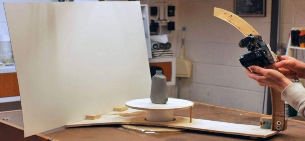
The scanner operates using a rotating platform system. The object is placed on a turntable, and a motor rotates it step-by-step while a camera captures images from multiple angles. These images are then processed in photogrammetry software, which reconstructs a 3D model based on overlapping features.
This method is effective because it simplifies the system: instead of moving the camera in multiple axes, we rotate the object itself. This reduces mechanical complexity and improves stability because the camera remains fixed, which removes one major source of vibration.
However, this simplicity requires very high mechanical consistency. If the rotation is not perfectly smooth or if there is any wobble, the reconstruction process becomes unstable because each image no longer aligns correctly in 3D space.
We also realized that timing between rotation and image capture is critical. Even small delays or irregular intervals can create mismatched datasets. In addition, lighting conditions strongly influence the quality of feature detection, meaning the system depends not only on mechanics but also on environment control.
3. Mechanical Design and Structure
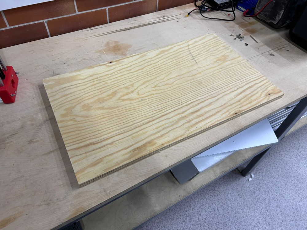
We chose to use a wooden base platform instead of fully 3D printing it. This decision improved rigidity and reduced vibration, both of which are critical for scanning quality. The base was still fully designed in CAD to ensure accurate positioning of all components.
The reason for selecting wood is that it provides much higher stiffness compared to large printed structures, especially when dealing with dynamic loads from a rotating system. It also reduces resonance, which is very important because resonance can amplify small motor vibrations into large visible movement.
The turntable was designed as a circular plate aligned precisely with the motor shaft. One of the biggest challenges was ensuring that the center of rotation was perfectly aligned. Even a small offset can create eccentric motion, which directly affects image alignment in photogrammetry.
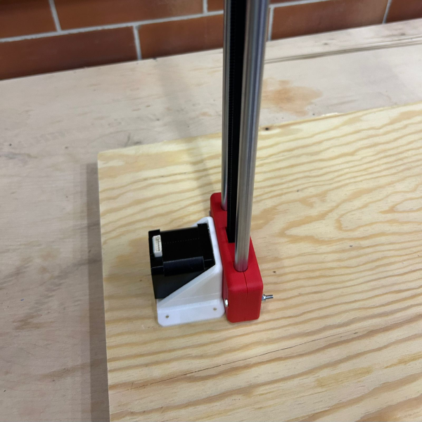
We also reinforced the motor mounting system to reduce vibration transfer. If the motor is not fixed rigidly, it introduces instability into the entire system. Therefore, we focused on strong mechanical connections and minimizing flexible joints.
4. First Prototype — 70° Curved Camera Mechanism
Our first design was a curved fixed mechanism that positioned the camera at approximately 70 degrees. This was not a tilt system, but a static geometry defined directly in CAD using an arc.
The idea behind this design was to improve surface coverage of the scanned object without adding extra moving parts or motors. We thought that by fixing the camera at an optimized angle, we could capture more detail from both top and side surfaces simultaneously.
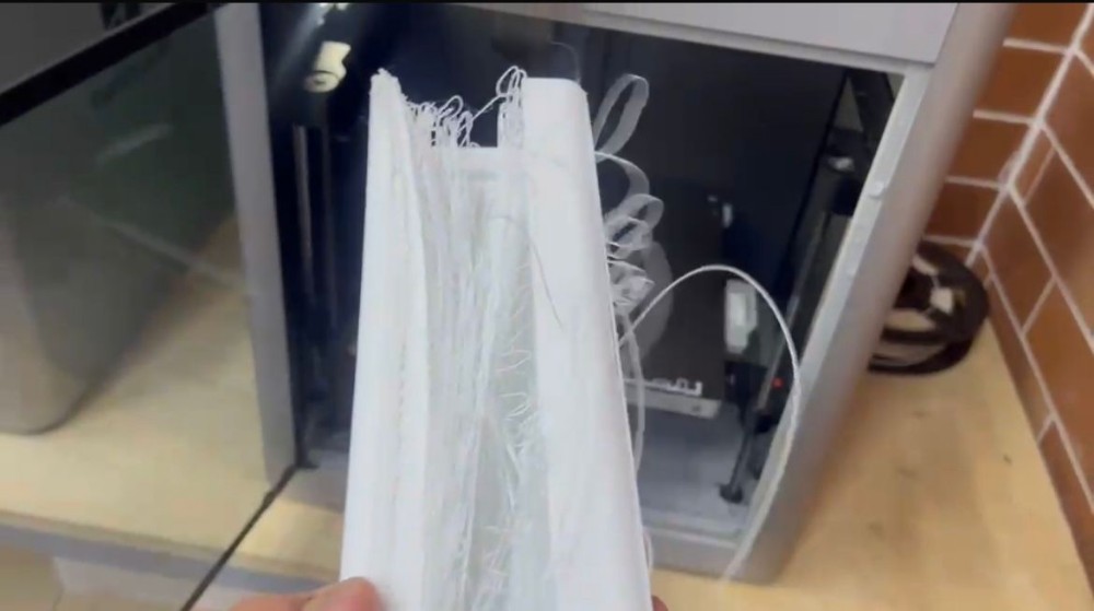
However, after fabrication and testing, multiple real-world issues appeared. The 3D printed structure was not stiff enough, which caused small bending under load. This bending changed the camera angle slightly, which was enough to affect image consistency.
We also observed that vibrations from the motor were transmitted directly into the camera structure, causing image blur. Since photogrammetry requires sharp and stable images, this became a critical failure point.
Another limitation was the lack of adjustability. Different objects require different camera angles, and a fixed system does not allow optimization.
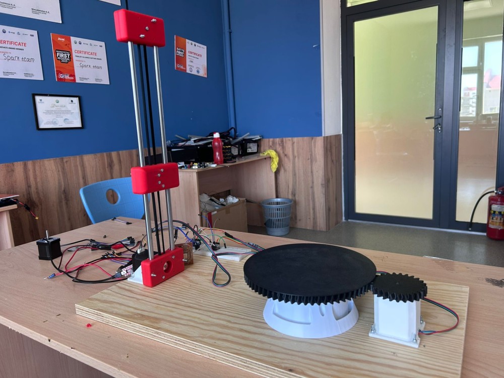
5. Final Solution — Belt-Driven Actuator
After analyzing the failure of the first prototype, we redesigned the system using a belt-driven actuator. This allowed smooth and adjustable positioning of the camera instead of a fixed angle.
In CAD, the system included a sliding mechanism, belt routing system, and a camera holder. The main idea was to replace rigid geometry with controlled motion.
This design significantly improved performance because the belt system absorbs small vibrations instead of transferring them directly. It also allows smoother movement compared to rigid printed structures.
Another advantage is flexibility. Now the camera position can be adjusted depending on object size and scanning requirements, which makes the system more universal.
6. Full System Integration
Once all components were finalized, we assembled the full machine. The system included a wooden base, rotating turntable, motor mount, and belt actuator. My main role was creating the full CAD assembly in Onshape, ensuring that all parts fit and functioned together correctly.
This step was critical because it allowed us to detect problems before fabrication, saving time and reducing errors during assembly.
During integration, we checked alignment between the camera, object center, and rotation axis. This is extremely important because even small misalignment leads to reconstruction errors.
We also verified mechanical clearances to ensure that moving parts do not collide during operation.
7. Testing and Results
During testing, we placed objects on the turntable and captured images while the platform rotated. These images were processed into 3D models using photogrammetry software.
The results showed that stable rotation greatly improves model quality. We also noticed that camera positioning plays a major role in how much detail is captured, especially on complex surfaces.
Small mechanical errors such as wobbling or vibration had a visible effect on reconstruction quality. Even if the system works mechanically, software output is still very sensitive to physical imperfections.
8. What Still Needs to Be Improved
This project also revealed several areas for improvement.
We need to improve alignment of the rotating axis because even small eccentricity affects output quality. Vibration reduction is also important, especially near the motor and camera mount.
Another improvement is automation. Currently, image capture is not fully synchronized with rotation, so adding automatic triggering would significantly improve consistency.
Lighting conditions also need improvement because uneven lighting reduces feature detection quality in photogrammetry.
9. Individual Contribution
My contribution focused on full CAD design of all components in Onshape, complete assembly modeling, mechanical problem solving, and redesign after the failed prototype.
I was responsible for ensuring that all parts of the system worked together as a single integrated machine, not just separate components.
I also focused heavily on alignment, tolerances, and system-level mechanical behavior.
10. Learning Outcomes
This project gave me a much deeper understanding of how real mechanical systems are designed and how they behave once they are physically built. One of the most important lessons was that CAD design and real-world performance are often very different. Even if a model looks perfect on the screen, real materials introduce unexpected behavior such as bending, vibration, friction, and tolerance errors.
I also learned how important iteration is in engineering. The first version of our system failed, but that failure was not a mistake — it was part of the learning process. Through testing and redesign, I was able to understand what actually matters in a working machine: stiffness, alignment, stability, and vibration control.
Another important outcome was improving my CAD and system thinking skills. Instead of designing single parts, I started thinking about the full system: how each component affects the others, how forces travel through the structure, and how small errors can multiply in a complex assembly.
I also gained experience in problem-solving under real constraints, such as limited materials, manufacturing accuracy, and time pressure. This helped me understand how engineers work in real projects, not just in theoretical environments.
Overall, this project improved my ability to think like an engineer, not just a designer.
11. Current Status
At the current stage, the mechanical part of the 3D scanner is fully completed and physically assembled. The system has been tested, and all main mechanical subsystems are working together as intended, including the rotating platform, base structure, motor mounting, and camera support system.
However, the project is still not completely finished because the software and control system are not implemented yet. The next stage of development will focus on automation, including motor control, synchronized camera triggering, and full scanning workflow integration.
Even though the system is not fully automated, the core mechanical foundation is stable and functional, which means the most critical part of the engineering work has already been successfully completed.
At this point, the system can already demonstrate a full scanning process manually, but it still requires code integration to become a fully autonomous machine.
12. Conclusion
In this week, we successfully designed, developed, and built a working 3D scanning system that combines mechanical design, structural engineering, and photogrammetry principles into a single integrated machine.
The project clearly showed that engineering development is not a linear process. Instead, it is an iterative cycle where design, failure, testing, and redesign all play an essential role in achieving a functional system.
The transition from the first prototype to the final belt-driven actuator system demonstrates how real engineering decisions evolve based on physical testing and real-world constraints.
What has been done in this project:
- Full mechanical CAD design of the entire scanner system
- Design and fabrication of rotating turntable mechanism
- Development of structural wooden base platform
- Design of initial curved camera mechanism (prototype stage)
- Redesign into belt-driven camera actuator system
- Full system assembly in Onshape
- Mechanical integration and alignment of all components
- Physical testing of rotating scanning system
- Photogrammetry-based 3D model generation
Final result:
The project successfully achieved a functional mechanical scanning system capable of:
- rotating object capture
- multi-angle image acquisition
- 3D model reconstruction using photogrammetry
- stable mechanical operation (prototype stage)
Even though software automation is still in development, the mechanical system is fully completed and represents a solid foundation for future upgrades.
This project proved that real engineering success comes from continuous improvement, testing, and adapting designs based on real-world feedback rather than relying only on theoretical models.