Week 2. Computer Aided Design
Week Assignment
Model (raster, vector, 2D, 3D, render, animate, simulate, …) a possible final project, compress your images and videos, and post a description with your design files on your class page
Learning Outcomes
- Evaluate and select 2D and 3D software
- Demonstrate and describe processes used in modelling with 2D and 3D softwares
- Demonstrate image and video compression
Introduction
This week I focused on Computer Aided Design (CAD) as part of the Fab Academy curriculum. The goal was to model a component of my final project using professional 3D modeling software, document the entire process step by step, and reflect on the tools and decisions made along the way.
For my final project I am building a robotic manipulator arm — a multi-joint mechanical arm capable of controlled, precise movement. I decided to focus this week specifically on the gear reducer, since in my opinion it is the most mechanically interesting and critical component of the whole arm. Without it, the raw rotational speed of the stepper motor is far too high and the torque far too low to move the arm in a useful and controlled way. The reducer solves this by transforming high-speed, low-torque rotation from the motor into slow, high-torque output — exactly what each joint of the manipulator needs.
I chose to model the entire reducer assembly in Onshape — a professional-grade, fully parametric CAD platform that runs entirely in the browser. I picked Onshape mainly because I could work from any computer in the lab without worrying about licenses or installations. Every sketch, every extrude, and every feature is saved automatically to the cloud with full version history and rollback support.
Why a Planetary Gear Reducer?
A planetary gear system (also called an epicyclic gear system) consists of three main elements:
- Sun gear — the central driving gear, connected directly to the motor shaft
- Planet gears — smaller gears that orbit around the sun gear while meshing with both it and the ring gear
- Ring gear — the outer gear with internal teeth that meshes with all planet gears simultaneously
This arrangement gives several key mechanical advantages over a simple spur gear pair:
- High gear ratio in a compact space — because the load is split across multiple planet gears, a meaningful reduction ratio is achievable without making the gearbox physically large
- Coaxial input and output — the motor shaft and the output shaft share the same centerline, which greatly simplifies integration into a robotic joint
- Even load distribution — multiple planet gears share the torque simultaneously, reducing stress on individual teeth and increasing service life
- High mechanical efficiency — planetary systems typically achieve 95–97% efficiency, meaning very little energy is wasted as heat
For a robotic manipulator, all of these properties matter enormously. Each joint must be compact, powerful, precise, and long-lasting. I designed this planetary reducer to fit directly on top of a standard Nema 17 stepper motor frame.
Software: Onshape
All modeling in this week's assignment was done entirely inside Onshape. Here is a comparison with other popular CAD tools I considered:
| Feature | Onshape | Fusion 360 | SolidWorks |
|---|---|---|---|
| Browser-based — no install required | ✅ | ❌ | ❌ |
| Free for students and makers | ✅ | ✅ (limited) | ❌ |
| Real-time collaboration | ✅ | ❌ | ❌ |
| Full parametric modeling | ✅ | ✅ | ✅ |
| Full version history with rollback | ✅ | ✅ | ✅ |
| STEP / IGES import | ✅ | ✅ | ✅ |
| Works on any OS or device | ✅ | ❌ | ❌ |
Onshape's Part Studio is where individual parts are modeled using a feature tree — a sequential list of operations (sketches, extrudes, revolves, fillets, boolean operations) that define each part's shape. The Assembly environment then brings all parts together with mates and constraints to verify fit and simulated motion.
Assembly Parts Overview
The complete reducer assembly I built in Onshape consists of the following parts:
| Part | Description | Role |
|---|---|---|
| Nema 17 Stepper Motor | 48mm, 1.8°/step, 76oz-in | Drive input |
| Housing body (Part 2) | Main reducer cylinder and frame | Fixed structure |
| Output cover (Part 7) | Top flange with bearing seat | Closes cavity, outputs rotation |
| Planet carrier (Part 6) | Rotating cage holding planet gears | Output shaft element |
| Spur gear — 55 teeth | Sun gear — on motor shaft | Input driver |
| Spur gear — 20 teeth ×2 | Large planet gears | Intermediate transmission |
| Spur gear — 15 teeth ×1 | Small planet gear | Intermediate transmission |
| Bearing 1611-0514-0006 ×3 | Ball bearings | Shaft and carrier support |
| M3 SHCS 10mm ×N | Socket head cap screws | Fasteners throughout |
3D Modeling Process — Step by Step
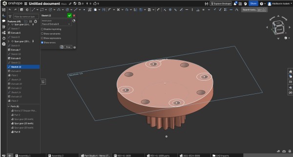
Step 1 — Output Flange with 6 Mounting Holes (Sketch 12)
The first element I tackled was the output interface — the top flange of the reducer that bolts directly to the next structural link in the robotic arm. I decided to start from the output and work inward — this way I made sure the reducer would actually fit the arm before committing to the internal geometry.
Sketch 12 defines the top output flange and features:
- Six M3 mounting holes at 60° intervals on a shared bolt circle — six holes instead of four for much better load distribution, since this is the highest-stress mechanical interface in the entire joint
- A central bore sized for a press-fit ball bearing, which supports the output shaft against both radial and axial forces from the arm
- The outer boundary of the flange, sized to match the housing body diameter for a clean flush edge
All holes were constrained with Onshape's circular pattern feature, keeping them perfectly equidistant.
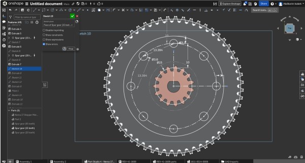
Step 2 — Sketch 10: Ring Gear & Planet Layout with Full Dimensions
This is the most geometrically complex and dimensionally critical sketch in the entire model. It defines the internal ring gear and precisely positions all planet gears, with every key dimension annotated directly on the sketch.
Key dimensions visible in this sketch:
- Planet gear center distance: 13.394 mm — the exact distance from the central sun gear axis to each planet gear center axis, derived from the gear pitch geometry:
(pitch_radius_sun + pitch_radius_planet) - Ring gear pitch circle: Ø83.6 mm — the working pitch diameter of the internal ring gear
- Hub bore: Ø15 mm — for seating the central output shaft ball bearing
The 13.394 mm center distance is not a guess — I calculated it from the gear module and tooth counts to ensure zero tooth interference. I then verified it in Onshape by overlaying all gear profiles in the same sketch and visually confirming that teeth mesh correctly with proper clearance.
Step 3 — Sun Gear Sketch: 55-Tooth Driving Gear
The sun gear is the heart of the planetary system — it is attached directly to the stepper motor shaft and simultaneously drives all planet gears at once. I built this sketch with extra care since any geometric error here propagates through the entire transmission.
Parameters of the sun gear I used:
- Number of teeth: 55
- Module: 1 mm — pitch diameter = 55 mm
- Bore: 5 mm with a D-flat keyway cut into the bore to prevent the gear spinning freely on the motor shaft under load
- Pressure angle: 20° — industry standard for most precision gearing applications
- Tooth profile: involute — constructed manually in Onshape using arc segments, tangency constraints, and bilateral mirror operations
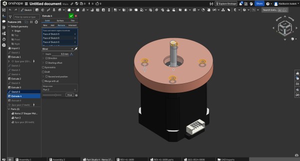
Step 4 — Extrude 4: Flange Cover at 2.2 mm
With the output flange sketch fully defined, I extruded it to create the physical cover plate of the reducer. I chose the depth of 2.2 mm based on three practical constraints:
- It matches the standard thickness of laser-cut or machined aluminum plate available in our Fab Lab
- It keeps the total axial height of the reducer as compact as possible
- At 2.2mm the cover has sufficient bending stiffness to not flex under the axial preload forces from the gear mesh
Step 5 — Sketch 6: Housing Flange with Bolt Holes
After extruding the cover geometry, I went back to define the structural top flange of the housing body itself. Sketch 6 defines:
- The outer diameter of the flange, set slightly larger than the gear housing cylinder below it to create a visible lip
- Four M3 bolt holes at 90° intervals on a shared bolt circle
- A central clearance hole for the planet carrier output shaft to pass through freely
Each bolt hole was dimensioned precisely and constrained symmetric about both centerlines using Onshape's symmetry mate.
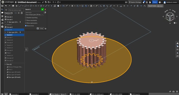
Step 6 — Sketch 2: Spur Gear Ring Profile
With the housing frame established, I moved on to defining the outer ring gear — the fixed internal gear that forms the outer mechanical boundary of the planetary system. The ring gear is fixed to the housing and does not rotate — it is the reaction element.
Key parameters I used:
- Internal teeth — pointing inward toward the axis
- Module: 1 mm — identical to all other gears
- Pressure angle: 20°
- Tooth count: 95 — derived from:
Ring = Sun + 2 × Planet = 55 + 2×20 = 95
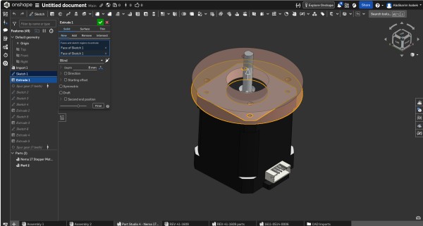
Step 7 — Extrude 1: Creating the Housing Base
With the foundational sketches ready, I applied the first Extrude to create the main 3D body of the reducer housing:
- Depth: 8 mm upward from the motor's top face
- Type: New solid — this created the very first 3D body in the Part Studio
- Profile: the outer circular housing boundary including the ring gear tooth form on the inner wall
The 8mm depth was determined by the gear tooth height (2 × module = 2mm) plus clearance above and below the gear face for structural material.
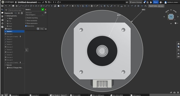
Step 8 — Importing the Nema 17 Stepper Motor & Base Reference Sketch
A crucial early step was importing the STEP file of the Nema 17 stepper motor. Rather than approximate the dimensions from a datasheet, I imported the manufacturer's exact STEP model and used it as the dimensional ground truth for the entire reducer.
On top of the motor I created Sketch 1 — the primary reference sketch that captures:
- Ø5 mm — motor shaft diameter → defines sun gear bore
- Ø60 mm — outer motor body reference → defines housing inner seating diameter
Everything in the reducer is parametrically linked to these two numbers.
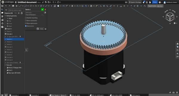
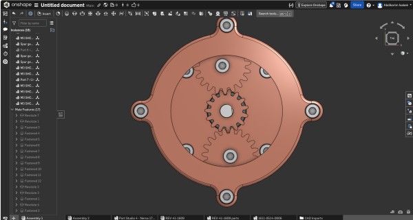
Step 9 — Top View: Internal Gear Layout Verification
I took this orthographic top-down view (with the cover removed) at an intermediate stage to verify the complete internal gear layout before committing to the final housing geometry. It shows:
- The 55-tooth sun gear centered on the motor shaft axis
- Two 20-tooth large planet gears at symmetrical positions
- One 15-tooth small planet gear completing the three-planet arrangement
- All gears visibly meshing correctly with the ring gear
Checking the assembly in top view was an important step for me — it allowed visual confirmation that no tooth profiles overlap and that the layout is geometrically consistent.
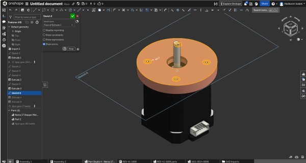
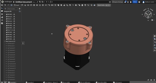
Step 10 — Completed Assembly: Isometric View
This is the final completed reducer assembly I made, viewed from an isometric perspective in Onshape's Part Studio. The copper-tone appearance was applied using Onshape's material appearance settings to make the housing visually distinct from the dark motor body below.
Everything is visible in this view:
- The ring gear teeth around the lower perimeter of the housing
- The top flange with its six M3 bolts
- The side mounting ears projecting from two opposite sides
- The output shaft protruding centrally from the top cover
- The Nema 17 motor cleanly integrated at the base
This view confirmed that all Part Studio features had merged correctly into the expected final geometry, with no unintended voids, gaps, or intersecting bodies.
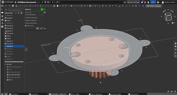
Step 11 — Sketch 18: Side Mounting Ears
To provide additional lateral attachment points for integrating the reducer into the manipulator arm frame, I added mounting ears to the outer housing body — flat tabs extending beyond the circular housing profile on two diametrically opposite sides.
Design details of each ear:
- M4 through-hole — one size larger than M3 because side-mounted bolts are loaded in shear rather than tension
- Generous fillet radii at the junction with the main housing cylinder — to avoid stress concentration points that could initiate fatigue cracks
- Flat bottom surface coplanar with the motor mounting face
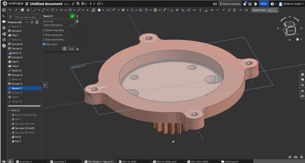
Step 12 — Final Output Cover with Bearing Seat (Sketch 17)
The output cover is the last and mechanically most demanding part I modeled. It simultaneously performs four functions: sealing the gear cavity, providing the bearing seat, retaining the output shaft axially, and defining the output torque interface of the entire assembly.
I revolved the cover sketch 360° using Onshape's Revolve feature. The profile contains:
- An outer seating rim with a close sliding fit (H7/g6 tolerance class)
- A machined bearing shoulder on the inner face — H7 interference fit with the bearing OD
- A central shaft bore as a clearance fit over the output shaft
- A shallow snap ring groove for tool-free disassembly
After revolving, I applied fillets to all interior sharp edges to eliminate stress concentrations.
Gear Ratio Calculation
Understanding the math behind the reducer was essential for me to design a manipulator with predictable, controllable motion. Here is the complete calculation:
Gear Parameters
Sun gear (input — Nema 17 shaft) :  55 teeth   (Zs)
Planet gears (large) × 2         :  20 teeth   (Zp_large)
Planet gear  (small) × 1         :  15 teeth   (Zp_small)
Ring gear    (fixed to housing)   :  95 teeth   (Zr)
Ring Gear Verification
For a valid planetary system, the ring gear tooth count must satisfy:
Zr = Zs + 2 × Zp_large
Zr = 55 + 2 × 20
Zr = 55 + 40
Zr = 95 teeth  ✓
Gear Ratio Formula
For a standard planetary gear system with a fixed ring gear, a rotating sun gear (input), and a rotating planet carrier (output):
                    Zr
Gear Ratio  =  1 + ────
                    Zs

                    95
            =  1 + ────
                    55

            =  1 + 1.7273

            =  2.7273

            ≈  2.73 : 1
Speed and Torque
Motor speed (Nema 17 typical):   200 RPM  (input)

                    200
Output speed   =  ───────  =  73.3 RPM
                   2.73

Torque multiplier  =  2.73 ×

If motor torque  =  0.40 N·m  (Nema 17 rated)
Output torque    =  0.40 × 2.73  =  1.09 N·m
Summary Diagram
                        ┌─────────────────────────────────────┐
                        │         PLANETARY REDUCER           │
                        │                                     │
  Nema 17 Motor         │   ┌──────────┐                     │
  ┌────────────┐         │   │ RING     │  95 teeth (fixed)  │
  │  200 RPM   │──shaft──┼──▶│   SUN    │  55 teeth (input)  │
  │  0.40 N·m  │         │   │  PLANET  │  20+20+15 teeth    │
  └────────────┘         │   │ CARRIER  │  (output)          │
                        │   └──────────┘                     │
                        │                                     │
                        └──────────────────┬──────────────────┘
                                           │
                                           ▼
                                   OUTPUT SHAFT
                                   73.3 RPM
                                   1.09 N·m
                                   Ratio: 2.73:1
The 2.73:1 reduction means the manipulator joint rotates at roughly one-third of the motor's speed, with 2.73 times more torque available. I chose this ratio as a balance between speed and torque for my specific arm design.
Design Files — Download STL
All parts are available as STL files for 3D printing or further CAD work:
| File | Part | Size |
|---|---|---|
Assembly 1 - Nema 17 Stepper Motor.stl |
Stepper motor reference body | 580 KB |
Assembly 1 - Part 2.stl |
Main reducer housing | 414 KB |
Assembly 1 - Part 7.stl |
Output cover / top flange | 388 KB |
Assembly 1 - Part 6.stl |
Planet carrier | 102 KB |
Assembly 1 - Spur gear (20 teeth).stl |
Large planet gear ×2 | 97 KB |
Assembly 1 - Spur gear (15 teeth).stl |
Small planet gear ×1 | 73 KB |
Assembly 1 - 1611-0514-0006.stl |
Ball bearing (main) | 227 KB |
Assembly 1 - 1611-0514-0006 (1).stl |
Ball bearing ×1 | 36 KB |
Assembly 1 - 1611-0514-0006 (2).stl |
Ball bearing ×2 | 36 KB |
Assembly 1 - M3 SHCS SS_10mm Long.stl |
M3×10 cap screw | 52 KB |
Reflections
Working entirely within Onshape for this assignment was a productive and instructive experience.
What worked well:
- The parametric feature tree made it easy to go back and modify earlier features — something I had to do several times when I realised earlier dimensions needed adjusting
- Sketch constraints kept all geometry correct as dimensions changed. I learned that a fully constrained sketch (shown in black in Onshape) is essential before moving to the next feature
- STEP import of the Nema 17 motor worked flawlessly — I was able to build the entire reducer directly on top of the real motor geometry without guessing any dimensions
- The browser-based environment meant I could work from any computer in the lab without any installation or license issues
Challenges I encountered:
- Generating accurate involute gear tooth profiles took a lot of time — there is no built-in gear generator in standard Onshape, so I had to construct everything manually with arcs and tangency constraints. Next time I will look for a FeatureScript plugin to speed this up
- Managing multiple solid bodies in a single Part Studio required careful attention to which body each Extrude or Boolean operation was targeting. I made mistakes here early on and had to rebuild some features
Summary
| Parameter | Value |
|---|---|
| Gear Type | Planetary (Epicyclic) |
| Drive Motor | Nema 17 Stepper Motor, 1.8°/step |
| Sun Gear Teeth | 55 |
| Large Planet Gear Teeth | 20 ×2 |
| Small Planet Gear Teeth | 15 ×1 |
| Ring Gear Teeth | 95 (fixed) |
| Gear Module | 1 mm |
| Pressure Angle | 20° |
| Gear Ratio | 2.73 : 1 |
| Output Speed (at 200 RPM input) | ≈ 73.3 RPM |
| Torque Multiplication | 2.73 × |
| CAD Software | Onshape (browser-based parametric CAD) |
| Export Format | STL (per part) + Onshape Document |
Video Compression
Part of this week's assignment was also to compress images and videos for the documentation website. When I recorded videos on my phone the files were very large — sometimes 200–300 MB for just a few minutes. That is too heavy to upload directly to the site, so I needed to compress them first.
I decided to use CapCut for this. It is a free mobile app for video editing and it has very good export settings where you can control the resolution, frame rate and bitrate. The whole process took me only a few minutes per video.
Step 1 — Open CapCut and Create a New Project
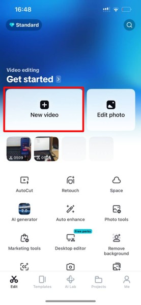
When you first open CapCut you see the main screen with all the editing options. The button you need is New video — it is the big button on the left side of the screen, highlighted in red in the screenshot above.
After pressing it, I selected the video I wanted to compress from my phone gallery and it loaded into the CapCut editor automatically. I didn't cut or edit anything here — just imported the video and moved to the next step.
Step 2 — Open the Export Panel
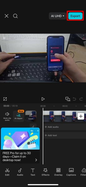
Once the video is in the timeline, tap the Export button in the top right corner — highlighted in red in the screenshot above. This opens the full export settings panel where you can change everything about how the video will be saved.
This step is important — if you just save the video without changing anything, CapCut will export it at original quality and the file will still be very large.
Step 3 — Set the Parameters and Export
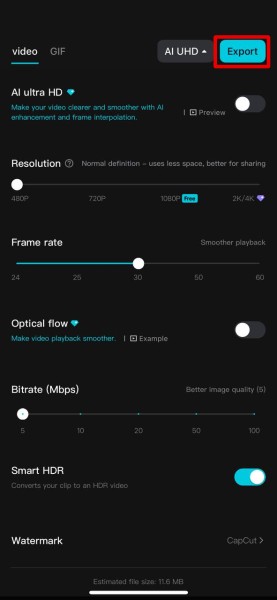
This is the most important step. In the export panel I changed the following settings:
| Setting | Value I used | Why |
|---|---|---|
| Resolution | 480p | Good quality, much smaller than 2K or 4K |
| Frame rate | 30 fps | Enough for documentation video |
| Bitrate | 5–10 Mbps | Lower = smaller file, still looks fine |
| AI Ultra HD | Off | Makes file bigger, not needed |
| Optical flow | Off | Only for slow motion effects |
| Smart HDR | Off | Not needed for normal footage |
CapCut shows you the estimated file size in real time as you move the bitrate slider — I used this to keep each video under 20 MB. After setting everything I pressed Export and uploaded the file to the Fab Academy documentation site.
Image Editing and Compression — Inkscape
For editing and compressing photos I used Inkscape — a free open source vector graphics editor already installed in our Fab Lab on Linux. My workflow for every documentation photo was the same four steps: open the image, draw red highlight boxes on the important parts, set the correct export dimensions, change the format to JPG, and save.
Step 1 — Open the Image and Add Red Highlight Boxes
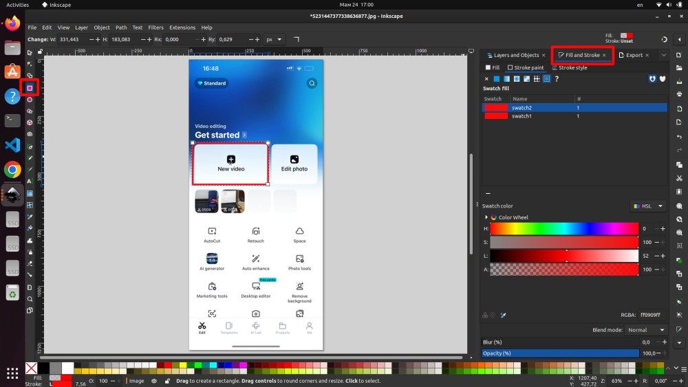
I opened the screenshot in Inkscape via File → Open. To mark the important parts I used the rectangle tool from the left toolbar, drew rectangles over the areas I wanted to highlight, then in the Fill and Stroke panel set the fill to none and the stroke color to red at 3–4 px thickness.
The RGBA color value I used was ff0909ff — a bright pure red. I kept the same color for all documentation images so everything looks consistent across the whole week page.
Step 2 — Resize the Image to the Correct Dimensions
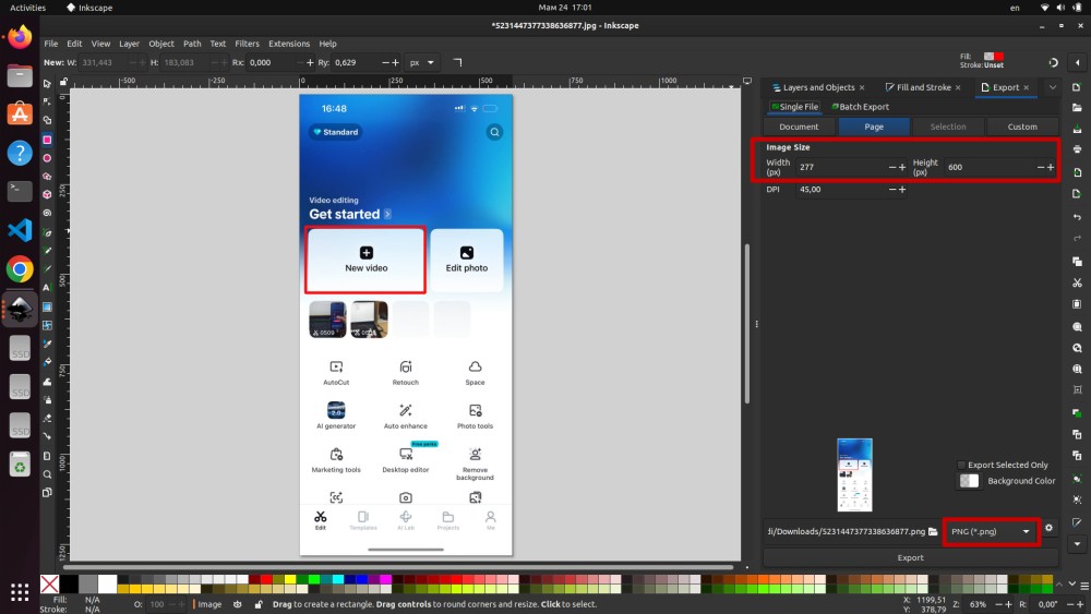
After adding the highlight boxes I opened the Export panel and clicked on the Page tab to set the output dimensions manually. For mobile phone screenshots I set the size to 277 × 600 px with DPI set to 45 — more than enough for web display, and it keeps the file size small.
Step 3 — Change the Export Format from PNG to JPG

By default Inkscape exports as PNG, but I always change this to JPEG (*.jpg). The reason is file size — a PNG screenshot from a phone can be 200–400 KB easily, while the same image as JPG is usually 20–50 KB. That is up to 10 times smaller with no visible quality difference for documentation purposes.
Step 4 — Name the File and Save
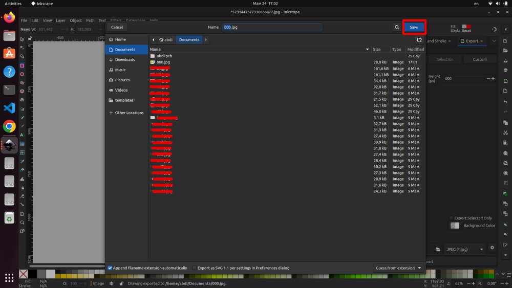
I named my files with simple numbered names like 000.jpg, 001.jpg and so on — this keeps them organized and easy to reference in the markdown. After pressing Save I moved the files into the files/ folder of my MkDocs documentation.
Conclusion
This week was really interesting and also quite challenging. I worked with three different tools — Onshape for 3D modeling, CapCut for video compression, and Inkscape for image editing and annotation — and each one taught me something useful.
The main result is the planetary gear reducer I designed for my robotic manipulator arm. The gear ratio came out at 2.73 : 1 which is a good balance between speed and torque. I modeled all the parts in Onshape: the housing, all the gears, the cover, the planet carrier, and all the mounting features.
The biggest lesson from Onshape was that you need to plan your sketches carefully from the beginning — if the first sketches are not fully constrained, everything that comes after can break when you change a dimension. I made this mistake a few times and had to go back and fix things. Drawing involute gear tooth profiles manually also took a lot of time, and next time I will look for a plugin to speed this up.
For image editing, Inkscape worked really well. The workflow of adding red highlight boxes, resizing, converting to JPG and saving became fast after doing it for all the documentation photos. The most useful thing I learned here is how much smaller JPG is compared to PNG — sometimes 10 times smaller with no visible quality difference.
For video compression CapCut was simple and effective. Setting 480p resolution and lowering the bitrate brought the file sizes down to under 20 MB which is comfortable for web hosting.
Overall I am happy with what I made this week and I feel ready to continue working on the rest of the manipulator in the next assignments.
Fab Academy 2026 · YU FabLab · Abdikarim