Week 14 — Interface and Application Programming
Assignments Overview
Individual Assignment
- Write an application that interfaces a user with an input &/or output device that you made.
Group Assignment
- Compare as many tool options as possible.
Introduction
This week focuses on Interface and Application Programming — the process of creating software interfaces that allow users to interact with physical hardware through digital applications. The core challenge is bridging the gap between the physical world (sensors, actuators, microcontrollers) and the digital world (web pages, desktop apps, GUIs) using well-defined communication protocols.
For my individual assignment, I developed two separate projects, each demonstrating a different approach to hardware-software interfacing:
- Project 1 — ESP8266-based web server for wireless LED control over HTTP
- Project 2 — Custom ESP8266 board for servo motor control via a web interface
Both projects use my custom-designed PCB boards fabricated in previous weeks of Fab Academy.
Project 1 — ESP8266 Wi-Fi LED Controller
Overview
In this project, I used my custom ESP8266 board to create a standalone Wi-Fi web server that controls two LEDs. The user connects to the same Wi-Fi network as the ESP8266 and navigates to the board's IP address in a browser to toggle the LEDs on and off.
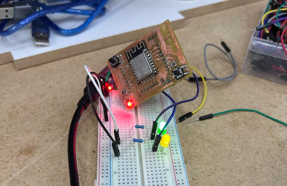
Hardware Setup
- Microcontroller: Custom PCB based on ESP8266 (ESP-12E/F module)
- Output Devices: 2× LEDs with current-limiting resistors
- Power Supply: 3.3V regulated supply via USB
The two LEDs are connected to digital GPIO pins on the ESP8266. Current-limiting resistors (220Ω) are placed in series with each LED to prevent damage.
Communication Protocol — HTTP over Wi-Fi (TCP/IP)
The ESP8266 connects to a local Wi-Fi access point and receives an IP address via DHCP. It then runs a lightweight HTTP server on port 80.
Protocol Stack used:
| Layer | Protocol |
|---|---|
| Application | HTTP/1.1 |
| Transport | TCP |
| Network | IP (IPv4) |
| Data Link | 802.11 Wi-Fi |
| Physical | ESP8266 RF module |
When the user opens a browser and navigates to the ESP8266's IP address (e.g., http://192.168.1.105), the following happens:
- The browser sends an HTTP GET request to the ESP8266
- The ESP8266 parses the request URL path (e.g.,
/led1/onor/led1/off) - Based on the path, it sets the corresponding GPIO pin HIGH or LOW
- The ESP8266 responds with an HTTP 200 OK response containing a simple HTML page showing the current state of both LEDs
This is a classic request-response pattern. There is no persistent connection — each button click is a new HTTP GET request.
Software — Arduino IDE
The firmware was written in C++ using the Arduino IDE with the ESP8266 Arduino Core library installed via the Board Manager.
Key libraries used:
- ESP8266WiFi.h — connects the board to the local Wi-Fi network
- ESP8266WebServer.h — handles incoming HTTP requests and routes them to handler functions
Workflow:
1. Install ESP8266 board package in Arduino IDE
2. Select board: Generic ESP8266 Module or NodeMCU 1.0
3. Write firmware (see code block below)
4. Flash via USB-to-Serial adapter
5. Open Serial Monitor to read the assigned IP address
Arduino Code
#include <ESP8266WiFi.h>
#include <ESP8266WebServer.h>

const char* ssid     = "YOUR_SSID";
const char* password = "YOUR_PASSWORD";

const int LED1_PIN = D1;
const int LED2_PIN = D2;

ESP8266WebServer server(80);

bool led1State = false;
bool led2State = false;

String buildPage() {
  String html = "<!DOCTYPE html><html><head>";
  html += "<meta charset='UTF-8'>";
  html += "<meta name='viewport' content='width=device-width, initial-scale=1'>";
  html += "<title>LED Controller</title>";
  html += "<style>";
  html += "body { font-family: Arial, sans-serif; text-align: center; padding: 40px; background: #1a1a2e; color: #eee; }";
  html += "h1 { color: #00d4ff; }";
  html += ".btn { display: inline-block; padding: 14px 32px; margin: 10px; font-size: 18px;";
  html += "border-radius: 8px; text-decoration: none; font-weight: bold; }";
  html += ".on  { background: #00d4ff; color: #000; }";
  html += ".off { background: #444; color: #eee; }";
  html += "</style></head><body>";
  html += "<h1>ESP8266 LED Controller</h1>";

  html += "<h2>LED 1 — ";
  html += led1State ? "ON" : "OFF";
  html += "</h2>";
  html += "<a class='btn on'  href='/led1/on'>Turn ON</a>";
  html += "<a class='btn off' href='/led1/off'>Turn OFF</a>";

  html += "<h2>LED 2 — ";
  html += led2State ? "ON" : "OFF";
  html += "</h2>";
  html += "<a class='btn on'  href='/led2/on'>Turn ON</a>";
  html += "<a class='btn off' href='/led2/off'>Turn OFF</a>";

  html += "</body></html>";
  return html;
}

void handleRoot()    { server.send(200, "text/html", buildPage()); }

void handleLed1On()  { led1State = true;  digitalWrite(LED1_PIN, HIGH); server.sendHeader("Location", "/"); server.send(302, "text/plain", ""); }
void handleLed1Off() { led1State = false; digitalWrite(LED1_PIN, LOW);  server.sendHeader("Location", "/"); server.send(302, "text/plain", ""); }
void handleLed2On()  { led2State = true;  digitalWrite(LED2_PIN, HIGH); server.sendHeader("Location", "/"); server.send(302, "text/plain", ""); }
void handleLed2Off() { led2State = false; digitalWrite(LED2_PIN, LOW);  server.sendHeader("Location", "/"); server.send(302, "text/plain", ""); }

void setup() {
  Serial.begin(115200);
  pinMode(LED1_PIN, OUTPUT);
  pinMode(LED2_PIN, OUTPUT);
  digitalWrite(LED1_PIN, LOW);
  digitalWrite(LED2_PIN, LOW);

  WiFi.begin(ssid, password);
  Serial.print("Connecting to Wi-Fi");
  while (WiFi.status() != WL_CONNECTED) {
    delay(500);
    Serial.print(".");
  }
  Serial.println("\nConnected!");
  Serial.print("IP Address: ");
  Serial.println(WiFi.localIP());

  server.on("/",         handleRoot);
  server.on("/led1/on",  handleLed1On);
  server.on("/led1/off", handleLed1Off);
  server.on("/led2/on",  handleLed2On);
  server.on("/led2/off", handleLed2Off);
  server.begin();
  Serial.println("HTTP server started.");
}

void loop() {
  server.handleClient();
}
Web Interface
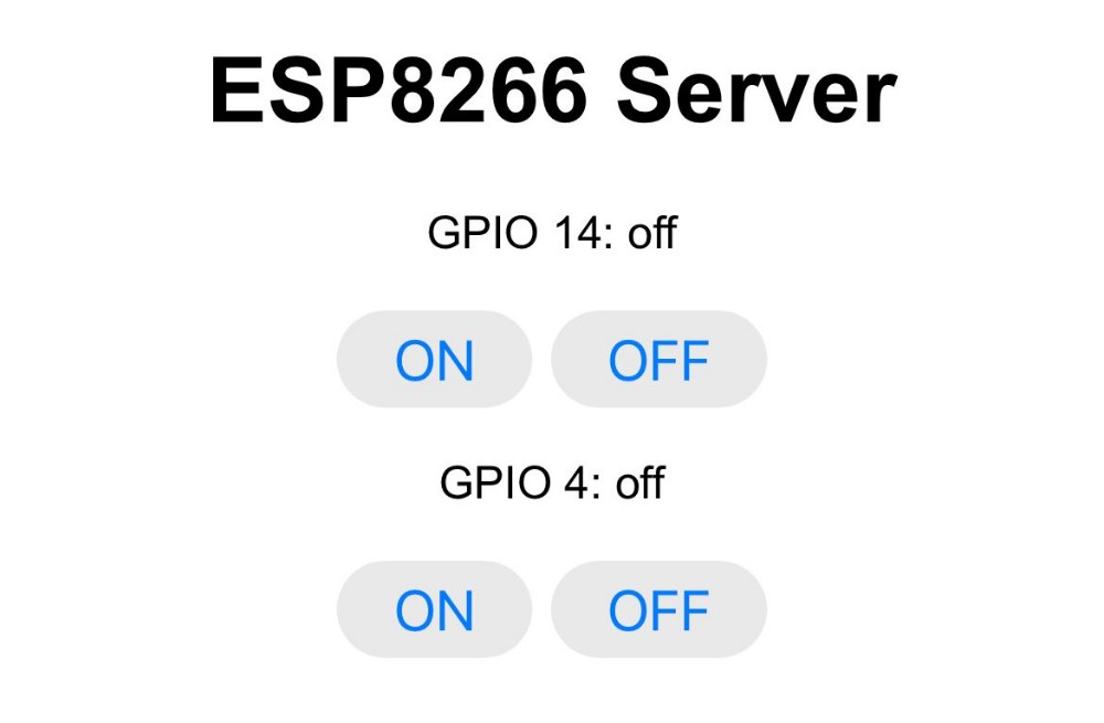
Once the ESP8266 boots up and connects to Wi-Fi, it prints its IP address to the Serial Monitor. Opening that address in any browser on the same network loads the control page.
How It Works — Data Flow Diagram
[User Browser]
     │
     │  HTTP GET /led1/on
     ▼
[ESP8266 Web Server]  ←── Wi-Fi (802.11) ───  [Router/Access Point]
     │
     │  digitalWrite(LED1_PIN, HIGH)
     ▼
[LED 1 on GPIO5]  →  💡 LED turns ON
Results
- Successfully connected ESP8266 to local Wi-Fi
- Obtained a dynamic IP address via DHCP
- Web interface loaded correctly in desktop and mobile browsers
- Both LEDs responded to button clicks with no noticeable delay
- HTTP server remained stable across multiple requests
Project 2 — Custom ESP8266 Servo Controller
Overview
In this project, I used my custom ESP8266 board to control a micro servo motor SG90 directly — without any additional microcontroller. The ESP8266 acts as both the Wi-Fi web server and the hardware controller. When the board boots up, it automatically creates its own Wi-Fi Access Point, so no external router is needed. The user connects their phone or laptop directly to the ESP8266's network, opens the web interface, and sets the servo angle. The SG90 rotates up to 90 degrees and automatically adjusts to whatever angle is sent from the browser.
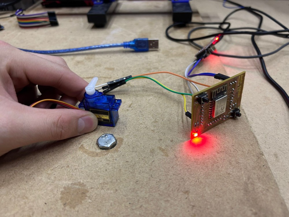
Hardware Setup
- Microcontroller: Custom PCB based on ESP8266 (ESP-12E/F module)
- Actuator: Micro servo SG90 (0°–90° range)
- Power Supply: 5V via USB; servo signal connected to GPIO pin (D1)
- No additional microcontroller needed — the ESP8266 handles everything
The SG90 servo signal wire is connected directly to a PWM-capable GPIO pin on the ESP8266. The ESP8266 generates the PWM signal natively using the Servo library ported for ESP8266.
Communication Protocol — HTTP over Wi-Fi (Access Point mode)
Instead of joining an existing Wi-Fi network, the ESP8266 creates its own Access Point on boot. This means the user does not need a router — they simply connect to the ESP8266's network (e.g., ServoControl) directly from any device and navigate to http://192.168.4.1 in the browser.
Protocol Stack used:
| Layer | Protocol |
|---|---|
| Application | HTTP/1.1 |
| Transport | TCP |
| Network | IP (IPv4) — 192.168.4.x subnet |
| Data Link | 802.11 Wi-Fi (AP mode) |
| Physical | ESP8266 RF module |
When the user submits the angle from the web page:
- The browser sends an HTTP GET request to
/servo?angle=VALUE - The ESP8266 parses the angle from the URL
- It constrains the value to the 0°–90° range
- It calls
myServo.write(angle)to physically rotate the SG90 - The page reloads showing the current angle
Software — Arduino IDE
The firmware was written in C++ using the Arduino IDE with the ESP8266 Arduino Core library.
Key libraries used:
- ESP8266WiFi.h — creates the Wi-Fi Access Point
- ESP8266WebServer.h — handles incoming HTTP requests
- Servo.h (ESP8266 port) — generates PWM signal for the servo
ESP8266 Code
#include <ESP8266WiFi.h>
#include <ESP8266WebServer.h>
#include <Servo.h>

const char* apSSID     = "ServoControl";
const char* apPassword = "12345678";

const int SERVO_PIN = D1;

ESP8266WebServer server(80);
Servo myServo;

int currentAngle = 0;

String buildPage() {
  String html = "<!DOCTYPE html><html><head>";
  html += "<meta charset='UTF-8'>";
  html += "<meta name='viewport' content='width=device-width, initial-scale=1'>";
  html += "<title>Servo Controller</title>";
  html += "<style>";
  html += "body { font-family: Arial, sans-serif; text-align: center; padding: 40px;";
  html += "background: #0f3460; color: #eee; }";
  html += "h1 { color: #e94560; }";
  html += "input[type=range] { width: 80%; margin: 20px 0; accent-color: #e94560; }";
  html += ".btn { background: #e94560; color: #fff; border: none; padding: 14px 36px;";
  html += "font-size: 18px; border-radius: 8px; cursor: pointer; margin-top: 10px; }";
  html += ".angle { font-size: 48px; font-weight: bold; color: #e94560; }";
  html += "</style></head><body>";
  html += "<h1>Servo Motor Controller</h1>";
  html += "<p class='angle' id='val'>" + String(currentAngle) + "°</p>";
  html += "<form action='/servo' method='GET'>";
  html += "<input type='range' name='angle' min='0' max='90' value='" + String(currentAngle) + "'";
  html += " oninput=\"document.getElementById('val').innerText=this.value+'°'\">";
  html += "<br><button class='btn' type='submit'>Set Angle</button>";
  html += "</form>";
  html += "</body></html>";
  return html;
}

void handleRoot() {
  server.send(200, "text/html", buildPage());
}

void handleServo() {
  if (server.hasArg("angle")) {
    currentAngle = server.arg("angle").toInt();
    currentAngle = constrain(currentAngle, 0, 90);
    myServo.write(currentAngle);
  }
  server.sendHeader("Location", "/");
  server.send(302, "text/plain", "");
}

void setup() {
  Serial.begin(115200);

  myServo.attach(SERVO_PIN);
  myServo.write(0);

  WiFi.softAP(apSSID, apPassword);
  Serial.println("Access Point started.");
  Serial.print("IP Address: ");
  Serial.println(WiFi.softAPIP());

  server.on("/",       handleRoot);
  server.on("/servo",  handleServo);
  server.begin();
  Serial.println("HTTP server started.");
}

void loop() {
  server.handleClient();
}
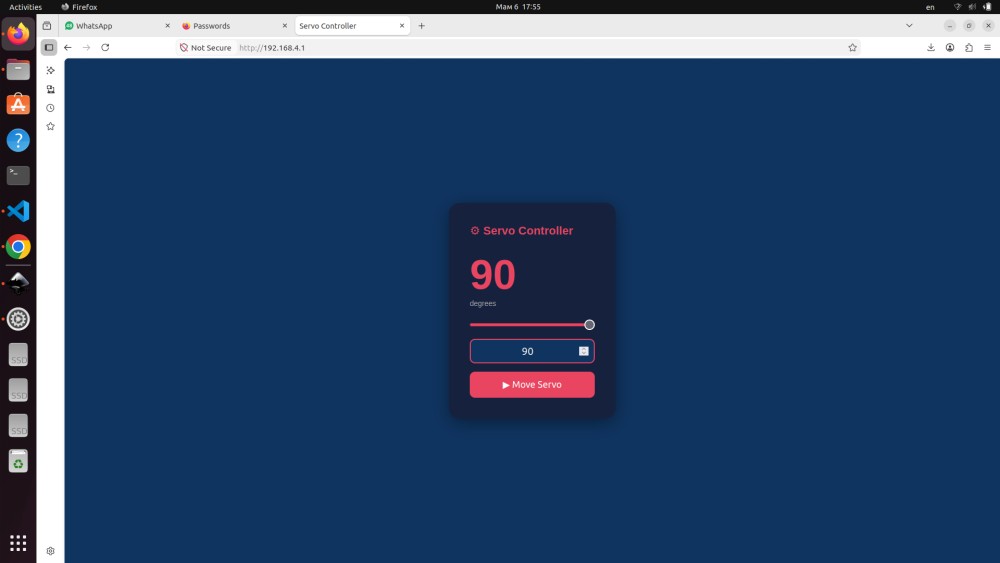
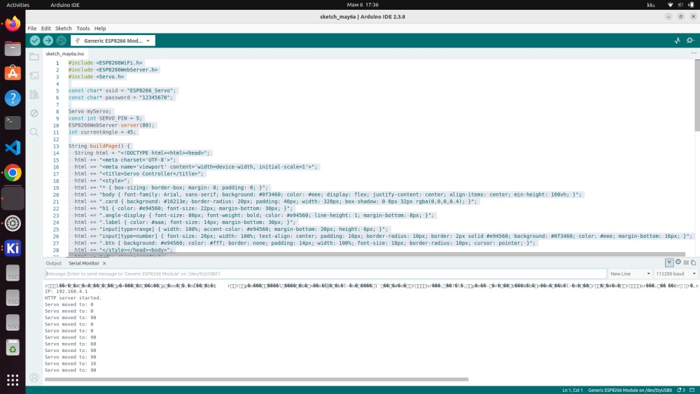
Web Interface
On boot the ESP8266 automatically broadcasts the Wi-Fi network "ServoControl". The user connects to it (password: 12345678) and opens http://192.168.4.1 in any browser. The page shows a range slider from 0° to 90°. Dragging the slider updates the displayed angle in real time. Pressing "Set Angle" sends the value to the ESP8266, which immediately rotates the SG90 to that exact position.
How It Works — Data Flow Diagram
[User Device]
     │  connects to Wi-Fi AP "ServoControl"
     │
     │  HTTP GET /servo?angle=45  (Wi-Fi / TCP / HTTP)
     ▼
[ESP8266 — AP + Web Server]
     │
     │  myServo.write(45)  (PWM signal on D1)
     ▼
[SG90 Micro Servo]  →  🔄 Rotates to 45°
Results
- ESP8266 successfully created its own Wi-Fi Access Point on every boot — no router required
- Web interface loaded correctly on both mobile and desktop browsers
- Servo angle slider limited to 0°–90° matching the physical range of the SG90
- Servo responded accurately to all tested angles (0°, 30°, 45°, 60°, 90°)
- Round-trip latency from browser click to physical servo movement was under 300ms
- System remained stable during extended testing sessions
Group Assignment — Comparing Interface & Application Programming Tools
For the group assignment, we compared multiple tools and frameworks that can be used to create interfaces for physical computing projects.
| Tool / Framework | Language | Protocol Support | Ease of Use | Best For |
|---|---|---|---|---|
| Arduino IDE + ESP8266WebServer | C++ | HTTP, WebSocket | ★★★★☆ | Embedded web servers |
| Processing | Java/Processing | Serial, OSC, TCP | ★★★★☆ | Desktop GUIs for serial devices |
| Node.js + Johnny-Five | JavaScript | Serial, HTTP, WebSocket | ★★★☆☆ | Web-connected hardware |
| Python + Flask + PySerial | Python | HTTP, Serial | ★★★★☆ | Rapid prototyping, Raspberry Pi |
| MIT App Inventor | Block-based | Bluetooth, HTTP | ★★★★★ | Android apps, no-code approach |
| p5.js | JavaScript | WebSerial API | ★★★★☆ | Browser-based serial interfaces |
| Node-RED | Flow-based | MQTT, HTTP, Serial | ★★★★☆ | IoT dashboards, visual programming |
| HTML/CSS/JS (vanilla) | JavaScript | HTTP, WebSocket | ★★★★★ | Custom lightweight web UIs |
Key Takeaways from Comparison
Arduino IDE + ESP8266WebServer is ideal when the microcontroller itself hosts the web server — no external computer is needed. It is self-contained and works entirely over local Wi-Fi using the HTTP protocol.
Python + Flask + PySerial is an excellent choice when a Raspberry Pi or laptop acts as the middleware: PySerial reads data from the Arduino over USB-Serial, and Flask exposes it as a web API that any browser can consume.
Node-RED excels at connecting many devices in an IoT pipeline using the MQTT protocol — perfect for more complex multi-device setups.
p5.js with the Web Serial API is a powerful browser-native approach that allows Chrome-based browsers to communicate directly with USB serial devices without any server middleware — useful for quick, interactive visualizations.
Reflection
What I Learned
- How to run an HTTP web server directly on a microcontroller (ESP8266)
- How to use ESP8266 in Access Point mode to create a self-contained Wi-Fi network without a router
- How to drive a servo motor directly from the ESP8266 without a secondary microcontroller
- The importance of matching the software angle range to the physical hardware limits of the servo
- How to build responsive HTML interfaces served from embedded hardware
- The tradeoffs between different interface programming approaches
Challenges Faced
- SG90 angle range: The SG90 physically rotates only 90 degrees. I limited the slider range in HTML (
max='90') and addedconstrain()in firmware to prevent sending out-of-range PWM values that could damage the servo. - ESP8266 PWM for servo: The standard Arduino
Servo.hlibrary does not support ESP8266 natively. I used the ESP8266-compatible port which generates the correct 50Hz PWM signal on GPIO pins. - Access Point IP address: In AP mode the ESP8266 always assigns itself
192.168.4.1, so the address is fixed and predictable — no need to check the Serial Monitor for a DHCP-assigned IP.
Future Improvements
- Add WebSocket support to enable real-time bidirectional communication without page reloads
- Add password protection to the web interface to prevent unauthorized access
- Explore MQTT protocol with a broker for more scalable IoT architectures
- Add a visual indicator on the web page (e.g. a dial graphic) showing the current servo position
Fab Academy — Week 14 | Interface and Application Programming Student: [Abdikarim] | Fab Lab: [YU FabLab]